US8884684B2 - Charge pump circuits having frequency synchronization with switching frequency of power converters - Google Patents
Charge pump circuits having frequency synchronization with switching frequency of power converters Download PDFInfo
- Publication number
- US8884684B2 US8884684B2 US14/025,969 US201314025969A US8884684B2 US 8884684 B2 US8884684 B2 US 8884684B2 US 201314025969 A US201314025969 A US 201314025969A US 8884684 B2 US8884684 B2 US 8884684B2
- Authority
- US
- United States
- Prior art keywords
- signal
- synchronization
- switching
- generating
- circuit
- Prior art date
- Legal status (The legal status is an assumption and is not a legal conclusion. Google has not performed a legal analysis and makes no representation as to the accuracy of the status listed.)
- Active
Links
Images


Classifications
-
- H—ELECTRICITY
- H02—GENERATION; CONVERSION OR DISTRIBUTION OF ELECTRIC POWER
- H02M—APPARATUS FOR CONVERSION BETWEEN AC AND AC, BETWEEN AC AND DC, OR BETWEEN DC AND DC, AND FOR USE WITH MAINS OR SIMILAR POWER SUPPLY SYSTEMS; CONVERSION OF DC OR AC INPUT POWER INTO SURGE OUTPUT POWER; CONTROL OR REGULATION THEREOF
- H02M3/00—Conversion of dc power input into dc power output
- H02M3/02—Conversion of dc power input into dc power output without intermediate conversion into ac
- H02M3/04—Conversion of dc power input into dc power output without intermediate conversion into ac by static converters
- H02M3/06—Conversion of dc power input into dc power output without intermediate conversion into ac by static converters using resistors or capacitors, e.g. potential divider
- H02M3/07—Conversion of dc power input into dc power output without intermediate conversion into ac by static converters using resistors or capacitors, e.g. potential divider using capacitors charged and discharged alternately by semiconductor devices with control electrode, e.g. charge pumps
-
- H—ELECTRICITY
- H03—ELECTRONIC CIRCUITRY
- H03L—AUTOMATIC CONTROL, STARTING, SYNCHRONISATION, OR STABILISATION OF GENERATORS OF ELECTRONIC OSCILLATIONS OR PULSES
- H03L7/00—Automatic control of frequency or phase; Synchronisation
- H03L7/06—Automatic control of frequency or phase; Synchronisation using a reference signal applied to a frequency- or phase-locked loop
- H03L7/08—Details of the phase-locked loop
-
- H—ELECTRICITY
- H02—GENERATION; CONVERSION OR DISTRIBUTION OF ELECTRIC POWER
- H02M—APPARATUS FOR CONVERSION BETWEEN AC AND AC, BETWEEN AC AND DC, OR BETWEEN DC AND DC, AND FOR USE WITH MAINS OR SIMILAR POWER SUPPLY SYSTEMS; CONVERSION OF DC OR AC INPUT POWER INTO SURGE OUTPUT POWER; CONTROL OR REGULATION THEREOF
- H02M3/00—Conversion of dc power input into dc power output
- H02M3/22—Conversion of dc power input into dc power output with intermediate conversion into ac
- H02M3/24—Conversion of dc power input into dc power output with intermediate conversion into ac by static converters
- H02M3/28—Conversion of dc power input into dc power output with intermediate conversion into ac by static converters using discharge tubes with control electrode or semiconductor devices with control electrode to produce the intermediate ac
- H02M3/325—Conversion of dc power input into dc power output with intermediate conversion into ac by static converters using discharge tubes with control electrode or semiconductor devices with control electrode to produce the intermediate ac using devices of a triode or a transistor type requiring continuous application of a control signal
- H02M3/335—Conversion of dc power input into dc power output with intermediate conversion into ac by static converters using discharge tubes with control electrode or semiconductor devices with control electrode to produce the intermediate ac using devices of a triode or a transistor type requiring continuous application of a control signal using semiconductor devices only
- H02M3/33569—Conversion of dc power input into dc power output with intermediate conversion into ac by static converters using discharge tubes with control electrode or semiconductor devices with control electrode to produce the intermediate ac using devices of a triode or a transistor type requiring continuous application of a control signal using semiconductor devices only having several active switching elements
- H02M3/33576—Conversion of dc power input into dc power output with intermediate conversion into ac by static converters using discharge tubes with control electrode or semiconductor devices with control electrode to produce the intermediate ac using devices of a triode or a transistor type requiring continuous application of a control signal using semiconductor devices only having several active switching elements having at least one active switching element at the secondary side of an isolation transformer
- H02M3/33592—Conversion of dc power input into dc power output with intermediate conversion into ac by static converters using discharge tubes with control electrode or semiconductor devices with control electrode to produce the intermediate ac using devices of a triode or a transistor type requiring continuous application of a control signal using semiconductor devices only having several active switching elements having at least one active switching element at the secondary side of an isolation transformer having a synchronous rectifier circuit or a synchronous freewheeling circuit at the secondary side of an isolation transformer
-
- H—ELECTRICITY
- H02—GENERATION; CONVERSION OR DISTRIBUTION OF ELECTRIC POWER
- H02M—APPARATUS FOR CONVERSION BETWEEN AC AND AC, BETWEEN AC AND DC, OR BETWEEN DC AND DC, AND FOR USE WITH MAINS OR SIMILAR POWER SUPPLY SYSTEMS; CONVERSION OF DC OR AC INPUT POWER INTO SURGE OUTPUT POWER; CONTROL OR REGULATION THEREOF
- H02M1/00—Details of apparatus for conversion
- H02M1/0003—Details of control, feedback or regulation circuits
- H02M1/0006—Arrangements for supplying an adequate voltage to the control circuit of converters
-
- H—ELECTRICITY
- H02—GENERATION; CONVERSION OR DISTRIBUTION OF ELECTRIC POWER
- H02M—APPARATUS FOR CONVERSION BETWEEN AC AND AC, BETWEEN AC AND DC, OR BETWEEN DC AND DC, AND FOR USE WITH MAINS OR SIMILAR POWER SUPPLY SYSTEMS; CONVERSION OF DC OR AC INPUT POWER INTO SURGE OUTPUT POWER; CONTROL OR REGULATION THEREOF
- H02M1/00—Details of apparatus for conversion
- H02M1/0003—Details of control, feedback or regulation circuits
- H02M1/0032—Control circuits allowing low power mode operation, e.g. in standby mode
-
- H—ELECTRICITY
- H02—GENERATION; CONVERSION OR DISTRIBUTION OF ELECTRIC POWER
- H02M—APPARATUS FOR CONVERSION BETWEEN AC AND AC, BETWEEN AC AND DC, OR BETWEEN DC AND DC, AND FOR USE WITH MAINS OR SIMILAR POWER SUPPLY SYSTEMS; CONVERSION OF DC OR AC INPUT POWER INTO SURGE OUTPUT POWER; CONTROL OR REGULATION THEREOF
- H02M1/00—Details of apparatus for conversion
- H02M1/44—Circuits or arrangements for compensating for electromagnetic interference in converters or inverters
-
- Y—GENERAL TAGGING OF NEW TECHNOLOGICAL DEVELOPMENTS; GENERAL TAGGING OF CROSS-SECTIONAL TECHNOLOGIES SPANNING OVER SEVERAL SECTIONS OF THE IPC; TECHNICAL SUBJECTS COVERED BY FORMER USPC CROSS-REFERENCE ART COLLECTIONS [XRACs] AND DIGESTS
- Y02—TECHNOLOGIES OR APPLICATIONS FOR MITIGATION OR ADAPTATION AGAINST CLIMATE CHANGE
- Y02B—CLIMATE CHANGE MITIGATION TECHNOLOGIES RELATED TO BUILDINGS, e.g. HOUSING, HOUSE APPLIANCES OR RELATED END-USER APPLICATIONS
- Y02B70/00—Technologies for an efficient end-user side electric power management and consumption
- Y02B70/10—Technologies improving the efficiency by using switched-mode power supplies [SMPS], i.e. efficient power electronics conversion e.g. power factor correction or reduction of losses in power supplies or efficient standby modes
Definitions
- the invention relates to a control circuit for a power converter and a method for generating a charge pump signal of a power converter.
- frequency of a charge pump is not always to be synchronized with switching frequency of the power converter, especially, at the light load, which will cause noise problem and not fit the customer's requirement.
- the present invention provides frequency synchronization for the charge pump circuit and the power converter.
- the frequency of the charger pump circuit will be synchronized with the switching frequency of the power converter, which will achieve lower noise for the power converter.
- the control circuit comprises a switching circuit and a charge pump circuit.
- the switching circuit generates a switching signal for controlling the power converter.
- the charge pump circuit comprises an oscillator for generating an oscillation signal synchronized with the switching signal.
- the oscillation signal is coupled to control a switch of the charge pump circuit for generating a voltage source.
- a method for generating a charge pump signal of a power converter comprises the step of generating a synchronization signal in response to a switching signal of the power converter; generating an oscillation signal synchronized with the synchronization signal; and generating the charge pump signal in accordance with the oscillation signal.
- the charge pump signal is coupled to control a switch for generating a voltage source.
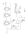
- FIG. 1 shows an exemplary embodiment of a control circuit for a power converter
- FIG. 2 is an exemplary embodiment of a synchronous oscillator of the control circuit in FIG. 1 ;
- FIG. 3 shows an exemplary of a filter 110 of the synchronous oscillator in FIG. 2 ;
- FIG. 4 shows an exemplary embodiment of a pulse generator 150 of the synchronous oscillator in FIG. 2 ;
- FIG. 5 shows an exemplary embodiment of a frequency multiplier 160 of the synchronous oscillator in FIG. 2 ;
- FIG. 6 shows waveforms of a sample signal, a pulse signal, a phase-lock signal, and a synchronization signal S YNC of the synchronous oscillator in FIG. 2 ;
- FIG. 7 shows an exemplary embodiment of a range-detection circuit of the synchronous oscillator in FIG. 2 ;
- FIG. 8 shows an exemplary embodiment of an oscillator of the synchronous oscillator in FIG. 2 ;
- FIG. 9 is a schematic view showing synchronization for waveforms of a synchronization signal, a ramp signal, a discharging signal, and an oscillation signal of the synchronous oscillator in FIG. 2 ;
- FIG. 10 shows an exemplary embodiment of a power converter to the present invention.
- FIG. 11 shows an exemplary embodiment of the synchronous rectifying circuit.
- FIG. 1 shows an exemplary embodiment of a control circuit for a power converter in accordance with the present invention.
- the control circuit comprises a switching circuit 10 and a charge pump circuit 20 .
- the switching circuit 10 generates a switching signal S W for regulating the output of the power converter.
- the charge pump circuit 20 comprises a synchronous oscillator (SYNC SOC) 100 coupled to receive the switching signal S W for generating a power source V DD .
- the power source V DD is further coupled to supply the power to the switching circuit 10 .
- the switching circuit 10 can operate as a synchronous rectifying control circuit, and, thus, the switching signal S W serves as a synchronous rectifying signal.
- FIG. 2 is an exemplary embodiment of the synchronous oscillator 100 in accordance with the present invention.
- the synchronous oscillator 100 comprises a filter 110 , a pulse generator 150 , a frequency multiplier (M) 160 , a range-detection circuit (RANGE) 200 , and an oscillator (OSC) 300 .
- the filter 110 is coupled to receive the switching signal S W and generate an input signal S IN .
- the input signal S IN is coupled to the pulse generator 150 for generating a pulse signal PLS and a sample signal PLP.
- the frequency multiplier 160 generates a synchronization signal S YNC in response to the pulse signal PLS and the sample signal PLP.
- the synchronization signal S YNC has the frequency twice the frequency of the pulse signal PLS.
- the synchronization signal S YNC is further coupled to the range-detection circuit 200 to generate an enable signal SYN-EN if the frequency of the synchronization signal S YNC is within a range.
- the enable signal SYN-EN will be enabled if the period of the synchronization signal S YNC is longer than a minimum-period and shorter than a maximum-period.
- the oscillator 300 will generate an oscillation signal S OSC in accordance with the synchronization signal S YNC , such that the oscillation signal S OSC is synchronized with the synchronization signal S YNC .
- the enable signal SYN-EN is disabled. Once the enable signal SYN-EN is disabled, the oscillator 300 will generate the oscillation signal S OSC without the synchronization (free run).
- the oscillation signal S OSC is utilized to switch the charge pump circuit 20 .
- the filter 110 , the pulse generator 150 , and the frequency multiplier 160 form a synchronization circuit for generating the synchronization signal S YNC is in response to the switching signal S W .
- the synchronization signal S YNC has a frequency multiplied in response to a frequency of the switching signal S W .
- FIG. 3 shows an exemplary of the filter 110 .
- the input signal S IN is generated in accordance with the switching signal S W .
- the filter 110 comprises current sources 112 and 114 , a transistor 115 , a capacitor 117 , and a inverter 119 .
- the current source 112 has a first terminal coupled to a voltage source V CC and a second terminal.
- the gate of the transistor 115 receives the switching signal S W , and the drain thereof is coupled to the second terminal of the current source 112 .
- the current source 114 has a first terminal coupled to the source of the transistor 115 and a second terminal coupled to the ground.
- the capacitor 117 has a first terminal coupled to the joint point of the current source 112 and the transistor 115 and a second terminal coupled to the ground.
- the input terminal of the inverter 119 is coupled to the joint point of the current source 112 and the transistor 115 , and the output thereof generates the input signal S IN .
- the current sources 112 and 114 associated with the capacitor 117 provide a low-pass filtering for generating the input signal S IN .
- FIG. 4 shows an exemplary embodiment of the pulse generator 150 .
- the pulse signal PLS is generated in response to the rising edge for the input signal S IN .
- the pulse generator 150 includes an inverter 151 , a current source 152 , a transistor 153 , a capacitor 155 , an inverter 156 , an AND gate 157 , and a pulse generation circuit 159 .
- the current source 152 is coupled to charge the capacitor 155 .
- the transistor 153 is coupled to discharge the capacitor 155 .
- the input signal S IN is coupled to control the transistor 153 through the inverter 151 .
- the input signal S IN is further coupled to an input of the AND gate 157 . Another input of the AND gate 157 is coupled to the capacitor 155 via the inverter 156 .
- the pulse signal PLS is generated at the output of the AND gate 157 .
- the pulse width of the pulse signal PLS is determined by the current of the current source 152 and the capacitance of the capacitor 155 .
- the pulse generation circuit 159 receives the pulse signal PLS.
- the pulse generation circuit 159 is further coupled to generate the sample signal PLP in response to the rising edge of the pulse signal PLS.
- the pulse width of the sample signal PLP is shorter than the pulse width of the pulse signal PLS.
- FIG. 5 shows an exemplary embodiment of the frequency multiplier 160 in accordance to the present invention.
- An inverter 161 receives the sample signal PLP to generate an inverse signal S I .
- the pulse signal PLS and the inverse signal of the sample signal PLP are coupled to discharge a capacitor 165 through an AND gate 162 and a transistor 163 .
- a current source 164 associated with the capacitor 165 generate a ramp signal RMP in accordance with the period of the pulse signal PLS.
- the level (peak level) of the ramp signal RMP is sampled into a capacitor 168 through a switch 167 .
- the sample signal PLP controls the switch 167 .
- a unit-gain buffer amplifier 170 is coupled to the capacitor 168 to generate a divided signal via resistors 171 and 172 .
- the divided signal is further coupled to a comparator 175 to compare with the ramp signal RMP for generating a phase-lock signal VLS through a pulse generator 180 .
- the phase-lock signal VLS is thus generated between two pulses of the pulse signal PLS.
- the synchronization signal S YNC is generated by an OR gate 185 in accordance with the pulse signal PLS and the phase-lock signal VLS.
- the synchronization signal S YNC has the frequency twice frequency of the pulse signal PLS and the switching signal S W .
- FIG. 6 shows the waveforms of the sample signal PLP, the pulse signal PLS, the phase-lock signal VLS, and the synchronization signal S YNC .
- FIG. 7 shows an exemplary embodiment of the range-detection circuit 200 in accordance with the present invention.
- a current source 210 and a capacitor 215 determine a low-pass time constant.
- the current source 232 and a capacitor 235 determine a high-pass time constant.
- the synchronization signal S YNC is coupled to discharge the capacitor 215 via a transistor 211 .
- a comparator 251 compares the voltage level of the capacitor 215 with a threshold voltage V T and generates a low-pass signal LOPAS if the voltage level of the capacitor 215 is higher than the threshold voltage V T .
- the low-pass signal LOPAS will be coupled to reset a counter through an AND gate 258 if the period of the synchronization signal S YNC is longer than the low-pass time constant.
- a current source 230 and a capacitor 235 determine a high-pass time constant.
- the synchronization signal S YNC is coupled to discharge the capacitor 235 via a transistor 231 .
- a comparator 252 compares the voltage level of the capacitor 235 with the threshold voltage V T and generates a high-pass signal HIPAS if the voltage level of the capacitor 235 is lower than the threshold voltage V T .
- the high-pass signal HIPAS will be coupled to reset the counter through the AND gate 258 if the period of the synchronization signal S YNC is shorter than the high-pass time constant.
- Flip-flops 261 and 268 develop the above counter.
- a flip-flop 269 operates as a latch. The synchronization signal S YNC clocks the counter and the flip-flop 269 .
- the counter will generate the enable signal SYN-EN if the frequency of the synchronization signal S YNC is within a specific range. It means the enable signal SYN-EN will be enabled if the period of the synchronization signal S YNC is longer than the minimum-period and shorter than the maximum-period.
- the low-pass time constant is related to the maximum-period.
- the high-pass time constant is related to the minimum-period. If the period of the synchronization signal S YNC is within the minimum-period and the maximum-period, the enable signal SYN-EN will be enabled after a delay. The delay is determined by a number of cycles of synchronization signal SYNC through the counter.
- FIG. 8 shows an exemplary embodiment of the oscillator 300 in accordance with the present invention.
- a current source 310 charges a capacitor 320 via a switch 311 for generating a ramp signal S RMP .
- a current source 315 is coupled to discharge the capacitor 320 via a switch 316 .
- Comparators 331 and 332 are coupled to receive the ramp signal S RMP for comparing with trip-point voltages VH and, VL, respectively.
- NAND gates 341 and, 342 form a latch circuit coupled to receive the outputs of the comparators 331 and 332 for generating a discharging signal S D .
- An inverter 346 generates a charging signal S C in accordance with the discharging signal S D .
- the charging signal S C is further coupled to generate the oscillation signal S OSC through an inverter 347 and a flip-flop 350 .
- the charging signal S C is coupled to control the switch 311 .
- the discharging signal S D is coupled to control the switch 316 .
- the synchronization signal S YNC is coupled to turn on a flip-flop 375 .
- the output of the flip-flop 375 is further coupled to turn on a current source 370 for speeding up the charge time of the capacitor 320 if the enable signal SYN-EN is enabled.
- the discharging signal S D is coupled to reset the flip-flop 375 via an inverter 376 .
- the ramp signal S RMP will be synchronized with the synchronization signal S YNC if the enable signal SYN-EN is enabled.
- FIG. 9 shows the synchronization for the waveforms of the synchronization signal S YNC , the ramp signal S RMP , the discharging signal S D , and the oscillation signal S OSC .
- FIG. 10 shows an exemplary embodiment of a power converter to the present invention.
- the power converter comprises a transformer 30 , a transistor 35 , a resistor 40 , a capacitor 45 , a metal oxide semiconductor field effect transistor (MOSFET) 50 , a diode 55 , a charge-pump capacitor 70 , and a capacitor 80 .
- the transformer 30 receives an input voltage V IN .
- the transistor 35 is used to switch the transformer 30 for regulating an output voltage V O across the capacitor 45 .
- a synchronous rectifying controller 500 generates the switching signal S W by a switching circuit to serve as a control signal for controlling the MOSFET 50 operated as a synchronous rectifier (SR).
- the synchronous rectifying controller 500 comprises the charge pump circuit to switch the charge-pump capacitor 70 for pumping the voltage source V DD on the capacitor 80 .
- FIG. 11 shows an exemplary embodiment of the synchronous rectifying controller 500 according to the present invention.
- the synchronous rectifying controller 500 includes a switching-signal generator 570 to generate the switching signal S W for the synchronous rectifying.
- the synchronous oscillator 100 generates the oscillation signal S OSC in response to the switching signal S W .
- the oscillation signal S OSC is coupled to a drive-signal generator 560 to generate drive signals (also referred to as charge pump signals) S 1 , S 2 , S 3 , and S 4 .
- the drive signals S 1 , S 2 , S 3 , and S 4 are coupled to control switches 501 , 502 , 503 , and 504 respectively for switching the charge-pump capacitor 70 and generating the voltage source V DD on the capacitor 80 .
- the frequency of the oscillation signal S OSC and the switching frequency of the drive signals S 1 , S 2 , S 3 , and S 4 are synchronized with the frequency of the switching signal S W .
Abstract
Description
Claims (12)
Priority Applications (1)
| Application Number | Priority Date | Filing Date | Title |
|---|---|---|---|
| US14/025,969 US8884684B2 (en) | 2012-10-29 | 2013-09-13 | Charge pump circuits having frequency synchronization with switching frequency of power converters |
Applications Claiming Priority (2)
| Application Number | Priority Date | Filing Date | Title |
|---|---|---|---|
| US201261719584P | 2012-10-29 | 2012-10-29 | |
| US14/025,969 US8884684B2 (en) | 2012-10-29 | 2013-09-13 | Charge pump circuits having frequency synchronization with switching frequency of power converters |
Publications (2)
| Publication Number | Publication Date |
|---|---|
| US20140118039A1 US20140118039A1 (en) | 2014-05-01 |
| US8884684B2 true US8884684B2 (en) | 2014-11-11 |
Family
ID=49934121
Family Applications (1)
| Application Number | Title | Priority Date | Filing Date |
|---|---|---|---|
| US14/025,969 Active US8884684B2 (en) | 2012-10-29 | 2013-09-13 | Charge pump circuits having frequency synchronization with switching frequency of power converters |
Country Status (3)
| Country | Link |
|---|---|
| US (1) | US8884684B2 (en) |
| CN (1) | CN103532354B (en) |
| TW (1) | TWI506927B (en) |
Citations (1)
| Publication number | Priority date | Publication date | Assignee | Title |
|---|---|---|---|---|
| US20100073082A1 (en) * | 2007-02-02 | 2010-03-25 | Mitsubishi Electric Corporation | Rectifier |
Family Cites Families (8)
| Publication number | Priority date | Publication date | Assignee | Title |
|---|---|---|---|---|
| US6965220B2 (en) * | 2002-11-14 | 2005-11-15 | Fyre Storm, Inc. | System for controlling a plurality of pulse-width-modulated switching power converters |
| CN100578904C (en) * | 2006-06-19 | 2010-01-06 | 崇贸科技股份有限公司 | Synchronization switching control circuit for power converter |
| US7460380B2 (en) * | 2006-06-26 | 2008-12-02 | System General Corp. | Highly efficient switching power converter using a charge pump to power the drive circuit |
| US20080062725A1 (en) * | 2006-09-11 | 2008-03-13 | Ta-Yung Yang | Multi-channels power converter having power saving means to improve light load efficiency |
| US7616461B2 (en) * | 2007-01-12 | 2009-11-10 | System General Corp. | Control method and circuit with indirect input voltage detection by switching current slope detection |
| US7616457B2 (en) * | 2007-11-20 | 2009-11-10 | System General Corp. | Synchronous regulation circuit |
| US7800923B2 (en) * | 2008-02-29 | 2010-09-21 | System General Corp. | Offline synchronous switching regulator |
| US8416587B2 (en) * | 2008-11-20 | 2013-04-09 | Silergy Technology | Synchronous rectifier control circuits and methods of controlling synchronous rectifiers |
-
2013
- 2013-09-13 US US14/025,969 patent/US8884684B2/en active Active
- 2013-10-28 TW TW102138850A patent/TWI506927B/en active
- 2013-10-29 CN CN201310519939.4A patent/CN103532354B/en active Active
Patent Citations (1)
| Publication number | Priority date | Publication date | Assignee | Title |
|---|---|---|---|---|
| US20100073082A1 (en) * | 2007-02-02 | 2010-03-25 | Mitsubishi Electric Corporation | Rectifier |
Also Published As
| Publication number | Publication date |
|---|---|
| US20140118039A1 (en) | 2014-05-01 |
| TWI506927B (en) | 2015-11-01 |
| CN103532354A (en) | 2014-01-22 |
| CN103532354B (en) | 2016-06-29 |
| TW201417468A (en) | 2014-05-01 |
Similar Documents
| Publication | Publication Date | Title |
|---|---|---|
| US8093955B2 (en) | Applying charge pump to realize frequency jitter for switched mode power controller | |
| US9190909B2 (en) | Control device for multiphase interleaved DC-DC converter and control method thereof | |
| JP6767867B2 (en) | Resonant power converter and control method | |
| US20100007394A1 (en) | Method and apparatus of providing a biased current limit for limiting maximum output power of power converters | |
| US11487311B2 (en) | Modulating jitter frequency as switching frequency approaches jitter frequency | |
| US9985549B2 (en) | Control of a dead time in a DC-DC converter | |
| JP2009123660A (en) | Discharge tube lighting device | |
| JP7095784B2 (en) | Switching power supply | |
| US7317362B2 (en) | Oscillator circuit and oscillation control method | |
| KR20090011715A (en) | Converter and the driving method thereof | |
| US9035636B2 (en) | Digital peak detector with follower mode | |
| CN102761275B (en) | A kind of former limit feedback AC-DC Switching Power Supply tremble control system frequently | |
| US8957650B2 (en) | Step-up/down DC-DC converter and switching control circuit | |
| US8988048B2 (en) | Circuit for generating a clock signal for interleaved PFC stages and method thereof | |
| EP3312982A1 (en) | Step-up/step-down dc/dc converter | |
| TWI496406B (en) | Power converter and method for controlling power converter | |
| US9742309B2 (en) | Waveform shape discriminator | |
| US8884684B2 (en) | Charge pump circuits having frequency synchronization with switching frequency of power converters | |
| TWI474595B (en) | Switching mode power supply with a spectrum shaping circuit | |
| CN116915071A (en) | Integrated circuit and power supply circuit | |
| KR20140072857A (en) | Converter and the driving method thereof | |
| JP2009111839A (en) | Triangular wave generator and switching regulator comprising the same | |
| JP2010252529A (en) | Pulse booster circuit and output-voltage control circuit |
Legal Events
| Date | Code | Title | Description |
|---|---|---|---|
| AS | Assignment |
Owner name: SYSTEM GENERAL CORPORATION, TAIWAN Free format text: ASSIGNMENT OF ASSIGNORS INTEREST;ASSIGNORS:YANG, TA-YUNG;WANG, CHOU-SHENG;TSENG, TSE-JEN;REEL/FRAME:031199/0238 Effective date: 20130813 |
|
| STCF | Information on status: patent grant |
Free format text: PATENTED CASE |
|
| AS | Assignment |
Owner name: FAIRCHILD (TAIWAN) CORPORATION, TAIWAN Free format text: CHANGE OF NAME;ASSIGNOR:SYSTEM GENERAL CORPORATION;REEL/FRAME:038599/0043 Effective date: 20140620 |
|
| AS | Assignment |
Owner name: SEMICONDUCTOR COMPONENTS INDUSTRIES, LLC, ARIZONA Free format text: ASSIGNMENT OF ASSIGNORS INTEREST;ASSIGNOR:FAIRCHILD (TAIWAN) CORPORATION (FORMERLY SYSTEM GENERAL CORPORATION);REEL/FRAME:042328/0318 Effective date: 20161221 |
|
| MAFP | Maintenance fee payment |
Free format text: PAYMENT OF MAINTENANCE FEE, 4TH YEAR, LARGE ENTITY (ORIGINAL EVENT CODE: M1551) Year of fee payment: 4 |
|
| AS | Assignment |
Owner name: DEUTSCHE BANK AG NEW YORK BRANCH, AS COLLATERAL AGENT, NEW YORK Free format text: PATENT SECURITY AGREEMENT;ASSIGNOR:SEMICONDUCTOR COMPONENTS INDUSTRIES, LLC;REEL/FRAME:046410/0933 Effective date: 20170210 Owner name: DEUTSCHE BANK AG NEW YORK BRANCH, AS COLLATERAL AG Free format text: PATENT SECURITY AGREEMENT;ASSIGNOR:SEMICONDUCTOR COMPONENTS INDUSTRIES, LLC;REEL/FRAME:046410/0933 Effective date: 20170210 |
|
| MAFP | Maintenance fee payment |
Free format text: PAYMENT OF MAINTENANCE FEE, 8TH YEAR, LARGE ENTITY (ORIGINAL EVENT CODE: M1552); ENTITY STATUS OF PATENT OWNER: LARGE ENTITY Year of fee payment: 8 |
|
| AS | Assignment |
Owner name: FAIRCHILD SEMICONDUCTOR CORPORATION, ARIZONA Free format text: RELEASE OF SECURITY INTEREST IN PATENTS RECORDED AT RECORDED AT REEL 046410, FRAME 0933;ASSIGNOR:DEUTSCHE BANK AG NEW YORK BRANCH, AS COLLATERAL AGENT;REEL/FRAME:064072/0001 Effective date: 20230622 Owner name: SEMICONDUCTOR COMPONENTS INDUSTRIES, LLC, ARIZONA Free format text: RELEASE OF SECURITY INTEREST IN PATENTS RECORDED AT RECORDED AT REEL 046410, FRAME 0933;ASSIGNOR:DEUTSCHE BANK AG NEW YORK BRANCH, AS COLLATERAL AGENT;REEL/FRAME:064072/0001 Effective date: 20230622 |