US888317A - Railroad-tie. - Google Patents
Railroad-tie. Download PDFInfo
- Publication number
- US888317A US888317A US38131007A US1907381310A US888317A US 888317 A US888317 A US 888317A US 38131007 A US38131007 A US 38131007A US 1907381310 A US1907381310 A US 1907381310A US 888317 A US888317 A US 888317A
- Authority
- US
- United States
- Prior art keywords
- tie
- railroad
- recesses
- rail
- key
- Prior art date
- Legal status (The legal status is an assumption and is not a legal conclusion. Google has not performed a legal analysis and makes no representation as to the accuracy of the status listed.)
- Expired - Lifetime
Links
- 238000006073 displacement reaction Methods 0.000 description 2
- 238000010276 construction Methods 0.000 description 1
- 238000004519 manufacturing process Methods 0.000 description 1
- 201000002266 mite infestation Diseases 0.000 description 1
Images
Classifications
-
- E—FIXED CONSTRUCTIONS
- E01—CONSTRUCTION OF ROADS, RAILWAYS, OR BRIDGES
- E01B—PERMANENT WAY; PERMANENT-WAY TOOLS; MACHINES FOR MAKING RAILWAYS OF ALL KINDS
- E01B3/00—Transverse or longitudinal sleepers; Other means resting directly on the ballastway for supporting rails
- E01B3/16—Transverse or longitudinal sleepers; Other means resting directly on the ballastway for supporting rails made from steel
Definitions
- s invention relates to new and useful improvements in railroad ties and it has more particular reference to a combined metallic railroad tie and fastener, the object being to provide a novel construction, combination and arrangement of parts.
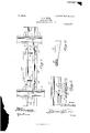
- Figure 1 is a top plan view showing the manner of use of a rail tie constructed in accordance with the present invention.
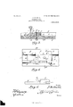
- Fig. 2 is an end elevation of such tie.
- Fig. 3 is a central longitudinal section thereof.
- Fig. 4 is a detailed view of the tie per se.
- Fig. 5 is a detailed view of an adjustable clamp.
- Fig. 6 is a detailed view of a locking key.
- the numeral 1 designates a tie which 1s formed with upwardly extending portions 2 arranged in arallel relation and affording a longitudina channel 3. In its lower face the tie is longitudinally grooved as at 4, for a purpose which will hereinafter ap car.
- he rail is designated by the numeral 5 and in the preferred embodiment of the invention seats on the faces of recesses 6 cut into the portions 2.
- the said portions 2 adjacent the outer ends of the tie areformed with inwardly pointing lips 7 which overlie and grip the flanges of the rail.
- the adjustable clamping member above referred to is designated generally by the numeral 8 and is mounted for adjustment longitudinally of the tie in the channel 3.
- the said member 8 is constructed with an extended base piece 9 which is disposed beneath the flange of the rail 5 and which is flush with the sides of the recesses 6.
- the member 8 includes an extended lip 10 formed to overlie the inner flange of the rail and said member at its inner end is formed with a recess 11. The.
- portions 2 adjacent the recesses 6 are constructed with respective enlarged openings 12 and reduced openings 13 and a tapering key 14 is inserted through these openings and through the recess 1 1, the latter having a tapered side to correspond to the tapered face of the key.
- the key 14 has a reduced threaded end 15 upon which is carried a jam nut 16.
- a bolt 17 is passed therethrough, through the base of the tie, and through a bearlng plate 18 disposed in the groove 4, and a nut 19 is engaged u on the end of said bolt to hold the parts tius assembled from displacement.
- the tie is constructed with diverging flanges 20 which assure its firm seating on the road bed.
- a rail tie constructed in accordance with the present invention is simple in its structural details, inexpensive to manufacture and practical and efficient in use.
- a rail tie formed with upwardly extending portions affording a channel longitudinally thereof, said upwardly extending portions being formed adjacent the ends of said tie with recesses and with inwardly pointing lips overhanging said recesses, said portions being further formed adjacent said recesses with registering openings, a clamping member constructed with an extended base portion flush with the faces of said recesses, with a lip overhanging said base portion, and
Landscapes
- Engineering & Computer Science (AREA)
- Architecture (AREA)
- Civil Engineering (AREA)
- Structural Engineering (AREA)
- Vehicle Step Arrangements And Article Storage (AREA)
Description
No. 888,317. PATENTED MAY 19, 1908} s. H. DEIHL.
RAILROAD TIE.
APPLICATION FILED JUNE 28, 1907.
2 SHEETS-SHEET 1.
i l a A l L? No. 888,317. PATENTED MAY 19, 1908.
' S. H. DEIHL.
RAILROAD TIE.
APPLICATION FILED JUNE 28. 1907.
2 SHEETSSHEET 2.
\ I amwm J? 53628;,
2/961 mom SYLVESTER H. DEIHL, OF ALTOONA, PENNSYLVANIA.
RAILROAD-TIE Specification of Letters Patent.
Patented May 19, 1908.
Application filed June 28, 1907. Serial No. 381,310.
To all whom it may concern:
Be it known that I, SYLVESTER H. DEIHL, a citizen of the United States, residing at Altoona, in the county of Blair, State of Pennsylvania, have invented certain new and useful Improvements in Railroad-Ties; and I do hereby declare the following to be a full, clear,
and exact description of the invention, such as will enable others skilled in the art to which it %%pertains to make and use the same.
s invention relates to new and useful improvements in railroad ties and it has more particular reference to a combined metallic railroad tie and fastener, the object being to provide a novel construction, combination and arrangement of parts.
The details of the invention will appear in the course of the following description, in which reference is had to the accompanying drawings forming a part of this specification, like characters of reference designating similar parts, throughout the several views, wherein:
Figure 1 is a top plan view showing the manner of use of a rail tie constructed in accordance with the present invention. Fig. 2 is an end elevation of such tie. Fig. 3 is a central longitudinal section thereof. Fig. 4 is a detailed view of the tie per se. Fig. 5 is a detailed view of an adjustable clamp. Fig. 6 is a detailed view of a locking key.
Referring specifically to the accompanying drawings, the numeral 1 designates a tie which 1s formed with upwardly extending portions 2 arranged in arallel relation and affording a longitudina channel 3. In its lower face the tie is longitudinally grooved as at 4, for a purpose which will hereinafter ap car.
he rail is designated by the numeral 5 and in the preferred embodiment of the invention seats on the faces of recesses 6 cut into the portions 2. The said portions 2 adjacent the outer ends of the tie areformed with inwardly pointing lips 7 which overlie and grip the flanges of the rail. The adjustable clamping member above referred to is designated generally by the numeral 8 and is mounted for adjustment longitudinally of the tie in the channel 3. The said member 8 is constructed with an extended base piece 9 which is disposed beneath the flange of the rail 5 and which is flush with the sides of the recesses 6. In addition to the base piece 9 the member 8 includes an extended lip 10 formed to overlie the inner flange of the rail and said member at its inner end is formed with a recess 11. The. portions 2 adjacent the recesses 6 are constructed with respective enlarged openings 12 and reduced openings 13 and a tapering key 14 is inserted through these openings and through the recess 1 1, the latter having a tapered side to correspond to the tapered face of the key. The key 14 has a reduced threaded end 15 upon which is carried a jam nut 16.
After the member 8 has been locked against displacement longitudinally of the tie by the key 14, a bolt 17 is passed therethrough, through the base of the tie, and through a bearlng plate 18 disposed in the groove 4, and a nut 19 is engaged u on the end of said bolt to hold the parts tius assembled from displacement. It is to be noted that the tie is constructed with diverging flanges 20 which assure its firm seating on the road bed.
A rail tie constructed in accordance with the present invention is simple in its structural details, inexpensive to manufacture and practical and efficient in use.
From the foregoing description it will be seen that simple and efiicient means are provided for accomplishing the objects of the invention, but while the elements herein shown and described are well adapted to serve the functions set forth, it is obvious that various minor changes may be made in the proportions, shape and arrangement of the several parts, without departing from the spirit and scope of the invention as defined in the appended claims.
What is claimed is:
A rail tie formed with upwardly extending portions affording a channel longitudinally thereof, said upwardly extending portions being formed adjacent the ends of said tie with recesses and with inwardly pointing lips overhanging said recesses, said portions being further formed adjacent said recesses with registering openings, a clamping member constructed with an extended base portion flush with the faces of said recesses, with a lip overhanging said base portion, and
With a recess at its inner end, a key engaged In testimony whereof, I affiX my signature, thrplugh the openin%s said1 u wardly eX- in presence of tWo Witnesses. ten ing portions an t rou t e recess in said clamping portion and f rmed with a re- SYLVESTER DEIHL' 5 duced projecting threaded end, and a jam Witnesses:
nut provided upon the threaded end of said B. MANGEs, key. A. BRUMBAUGH.
Priority Applications (1)
| Application Number | Priority Date | Filing Date | Title |
|---|---|---|---|
| US38131007A US888317A (en) | 1907-06-28 | 1907-06-28 | Railroad-tie. |
Applications Claiming Priority (1)
| Application Number | Priority Date | Filing Date | Title |
|---|---|---|---|
| US38131007A US888317A (en) | 1907-06-28 | 1907-06-28 | Railroad-tie. |
Publications (1)
| Publication Number | Publication Date |
|---|---|
| US888317A true US888317A (en) | 1908-05-19 |
Family
ID=2956750
Family Applications (1)
| Application Number | Title | Priority Date | Filing Date |
|---|---|---|---|
| US38131007A Expired - Lifetime US888317A (en) | 1907-06-28 | 1907-06-28 | Railroad-tie. |
Country Status (1)
| Country | Link |
|---|---|
| US (1) | US888317A (en) |
-
1907
- 1907-06-28 US US38131007A patent/US888317A/en not_active Expired - Lifetime
Similar Documents
| Publication | Publication Date | Title |
|---|---|---|
| US888317A (en) | Railroad-tie. | |
| US1065595A (en) | Rail-holding device. | |
| US961052A (en) | Metallic railroad-tie. | |
| US1011341A (en) | Joint-fastener for railway rails and ties. | |
| US982867A (en) | Railway-tie. | |
| US1013960A (en) | Metallic railroad. | |
| US1021661A (en) | Railroad-tie and lock. | |
| US1061037A (en) | Compound rail. | |
| US1138694A (en) | Metallic tie. | |
| US995386A (en) | Metal railway-tie. | |
| US1017965A (en) | Metallic railroad-tie. | |
| US972609A (en) | Railway-tie. | |
| US312566A (en) | William henry knowlton | |
| US896678A (en) | Railroad-tie. | |
| US764089A (en) | Metal railway-tie. | |
| US784793A (en) | Metallic railway-tie and rail-fastening device. | |
| US990615A (en) | Railway-rail tie and fastener. | |
| US433524A (en) | Thirds to thomas h | |
| US465263A (en) | Metallic railway-tie | |
| US857328A (en) | Metallic railway-tie. | |
| US1253779A (en) | Metallic railway-tie and rail-fastening. | |
| US770690A (en) | Railway-tie | |
| US499049A (en) | Ravlway-rail joint and fastening | |
| US478058A (en) | Railroad-tie | |
| US546744A (en) | Railroad-tie |