US8879956B2 - Intermediate transfer device and image forming apparatus including frame members - Google Patents
Intermediate transfer device and image forming apparatus including frame members Download PDFInfo
- Publication number
- US8879956B2 US8879956B2 US13/590,911 US201213590911A US8879956B2 US 8879956 B2 US8879956 B2 US 8879956B2 US 201213590911 A US201213590911 A US 201213590911A US 8879956 B2 US8879956 B2 US 8879956B2
- Authority
- US
- United States
- Prior art keywords
- intermediate transfer
- transfer member
- positioning
- members
- electrostatic latent
- Prior art date
- Legal status (The legal status is an assumption and is not a legal conclusion. Google has not performed a legal analysis and makes no representation as to the accuracy of the status listed.)
- Active, expires
Links
Images


Classifications
-
- G—PHYSICS
- G03—PHOTOGRAPHY; CINEMATOGRAPHY; ANALOGOUS TECHNIQUES USING WAVES OTHER THAN OPTICAL WAVES; ELECTROGRAPHY; HOLOGRAPHY
- G03G—ELECTROGRAPHY; ELECTROPHOTOGRAPHY; MAGNETOGRAPHY
- G03G15/00—Apparatus for electrographic processes using a charge pattern
- G03G15/01—Apparatus for electrographic processes using a charge pattern for producing multicoloured copies
- G03G15/0105—Details of unit
- G03G15/0131—Details of unit for transferring a pattern to a second base
-
- G—PHYSICS
- G03—PHOTOGRAPHY; CINEMATOGRAPHY; ANALOGOUS TECHNIQUES USING WAVES OTHER THAN OPTICAL WAVES; ELECTROGRAPHY; HOLOGRAPHY
- G03G—ELECTROGRAPHY; ELECTROPHOTOGRAPHY; MAGNETOGRAPHY
- G03G15/00—Apparatus for electrographic processes using a charge pattern
- G03G15/14—Apparatus for electrographic processes using a charge pattern for transferring a pattern to a second base
- G03G15/16—Apparatus for electrographic processes using a charge pattern for transferring a pattern to a second base of a toner pattern, e.g. a powder pattern, e.g. magnetic transfer
- G03G15/1605—Apparatus for electrographic processes using a charge pattern for transferring a pattern to a second base of a toner pattern, e.g. a powder pattern, e.g. magnetic transfer using at least one intermediate support
- G03G15/161—Apparatus for electrographic processes using a charge pattern for transferring a pattern to a second base of a toner pattern, e.g. a powder pattern, e.g. magnetic transfer using at least one intermediate support with means for handling the intermediate support, e.g. heating, cleaning, coating with a transfer agent
-
- G—PHYSICS
- G03—PHOTOGRAPHY; CINEMATOGRAPHY; ANALOGOUS TECHNIQUES USING WAVES OTHER THAN OPTICAL WAVES; ELECTROGRAPHY; HOLOGRAPHY
- G03G—ELECTROGRAPHY; ELECTROPHOTOGRAPHY; MAGNETOGRAPHY
- G03G21/00—Arrangements not provided for by groups G03G13/00 - G03G19/00, e.g. cleaning, elimination of residual charge
- G03G21/16—Mechanical means for facilitating the maintenance of the apparatus, e.g. modular arrangements
- G03G21/1661—Mechanical means for facilitating the maintenance of the apparatus, e.g. modular arrangements means for handling parts of the apparatus in the apparatus
- G03G21/168—Mechanical means for facilitating the maintenance of the apparatus, e.g. modular arrangements means for handling parts of the apparatus in the apparatus for the transfer unit
Definitions
- the present invention relates to an intermediate transfer device and an image forming apparatus.
- a tandem-type color printer which is a type of an image forming apparatus, includes four image forming units, each of which including components such as a charger, a developing device, and a photoconductor drum (an example of an electrostatic latent image carrier).
- the four image forming units form yellow (Y), magenta (M), cyan (C), and black (K) toner images (examples of developer images).
- the color toner images, which have been formed by the image forming units are transferred (first-transferred) to an intermediate transfer belt (an example of an intermediate transfer member) so as to overlap one another.
- an intermediate transfer belt an example of an intermediate transfer member
- the toner images on the intermediate transfer belt are transferred (second-transferred) to a sheet.
- the intermediate transfer belt to which the toner images are first-transferred, needs to keep a predetermined positional relationship with the photoconductor drum.
- the intermediate transfer belt is supported by frames (examples of frame members) that are disposed on the two sides of the intermediate transfer belt in the width direction of the intermediate transfer belt so as to be rotatable in the circumferential direction with plural rollers.
- the intermediate transfer belt, the frames, the rollers, and other members are unitized as an intermediate transfer device.
- an intermediate transfer device includes an endless intermediate transfer member to which plural developer images in different colors are transferred so as to overlap one another by a first-transfer unit; plural intermediate transfer member support members that support the intermediate transfer member so that the intermediate transfer member rotates in a circumferential direction; two frame members respectively disposed at two ends of the intermediate transfer member in a width direction of the intermediate transfer member, the two frame members supporting two ends of each of the intermediate transfer member support members; and first and second positioning members respectively disposed at two positions on each of the frame members with a distance therebetween, each of the first and second positioning members including a positioning portion that performs positioning by pressure-contacting an apparatus body when the intermediate transfer device is mounted in the apparatus body.
- FIG. 1 is a schematic view illustrating the structure of an image forming apparatus according to the exemplary embodiment of the present invention
- FIG. 2 is a perspective view of an intermediate transfer device to be mounted in the image forming apparatus of FIG. 1 ;
- FIG. 3 is a side view of the intermediate transfer device of FIG. 2 seen in a direction in which the intermediate transfer device is inserted into an apparatus body;
- FIG. 4 is a side view of the intermediate transfer device of FIG. 2 seen in a direction opposite to the direction in which the intermediate transfer device is inserted into an apparatus body;
- FIG. 5 is a plan view of the intermediate transfer device of FIG. 2 ;
- FIG. 6 is a perspective view of a removable mounting member that is used when inserting the intermediate transfer device of FIG. 2 into the apparatus body;
- FIG. 7 illustrates a frame of the intermediate transfer device of FIG. 2 ;
- FIG. 8 illustrates an observation result of the amount of strain in the frame of FIG. 7 when a protrusion of a positioning plate is located at an exemplary position
- FIG. 9 illustrates an observation result of the amount of strain in the frame of FIG. 7 when the protrusion of the positioning plate is located at another exemplary position
- FIG. 10 illustrates an observation result of the amount of strain in the frame of FIG. 7 when the protrusion of the positioning plate is located at another exemplary position
- FIG. 11 illustrates an observation result of the amount of strain in the frame of FIG. 7 when the protrusion of the positioning plate is located at another exemplary position
- FIG. 12 illustrates an observation result of the amount of strain in the frame of FIG. 7 when the protrusion of the positioning plate is located at another exemplary position
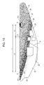
- FIG. 13 illustrates an observation result of the amount of strain in the frame of FIG. 7 when the protrusion of the positioning plate is located at another exemplary position
- FIG. 14 illustrates an observation result of the amount of strain in the frame of FIG. 7 when the protrusion of the positioning plate is located at another exemplary position.
- FIG. 1 illustrates a tandem-type digital color copier PR 1 , which is an example of an image forming apparatus according to an exemplary embodiment of the present invention.
- the digital color copier PR 1 includes, in an upper end portion thereof, a platen cover 3 that presses a document 2 against a platen glass 5 , and an image reading device 4 that reads an image of the document 2 placed on the platen glass 5 .
- the document 2 placed on the platen glass 5 is irradiated with light emitted from a light source 6 .
- Reflected light from the document 2 is scanned over an image reading element 11 , such as a CCD, via a reduction optical system including a full-rate mirror 7 , half-rate mirrors 8 and 9 , and an imaging lens 10 .
- the image reading element 11 reads a color reflected light image of the document 2 with a predetermined dot pitch.
- the color reflected light image of the document 2 which has been read by the image reading device 4 , is sent to an image processing device 12 as document reflection-rate data of three colors, such as red (R), green (G), and blue (B).
- the image processing device 12 performs image processing, such as shading correction, displacement correction, lightness/color-space conversion, gamma correction, frame erasing, and color/movement editing, on the reflection-rate data of the document 2 .
- the image data which has been processed by the image processing device 12 , is converted to four-color gradation document data (raster data) of yellow (Y), magenta (M), cyan (C), and black (K).
- the color gradation document data is sent to exposure devices 14 Y, 14 M, 14 C, and 14 K for yellow (Y), magenta (M), cyan (C), and black (K) (which are examples of exposures units and may be collectively referred to as the “exposure devices 14 ”) of image forming units 13 Y, 13 M, 13 C, and 13 K.
- Each of the exposure devices 14 performs image exposure in accordance with the color gradation document data by using a laser beam.
- the four image forming units 13 Y, 13 M, 13 C, and 13 K for yellow (Y), magenta (M), cyan (C), and black (K) (which may be collectively referred to as the “image forming units 13 ”) are arranged in a horizontal direction with a distance therebetween.
- the digital color copier PR 1 includes an electric circuit 49 including an image processing circuit that performs image processing on an image signal, a high-voltage power supply circuit, and the like.
- the four image forming units 13 Y, 13 M, 13 C, and 13 K have the same structure and each include a photoconductor drum 15 , 15 Y, 15 M, 15 C, and 15 K; a charger 16 , 16 Y, 16 M, 16 C, and 16 K for first charging; the exposure device 14 ; developing devices 17 Y, 17 M, 17 C, and 17 K; and a cleaning device 18 .
- the photoconductor drum 15 is an example of an electrostatic latent image carrier.
- the intermediate transfer belt 25 rotates in the direction of arrow A with a predetermined rotation speed.
- the charger 16 (an example of a charging unit) charges the surface of the photoconductor drum 15 .
- the exposure device 14 exposes the color images on the surface of the photoconductor drum 15 to light to form an electrostatic latent image.
- Each of the developing devices 17 Y, 17 M, 17 C, and 17 K (which are examples of developing units and may be collectively referred to as the “developing devices 17 ”) develops the electrostatic latent image formed on the photoconductor drum 15 to form a toner image (an example of a developer image).
- the cleaning device 18 removes toner that remains on the photoconductor drum 15 after the toner image has been transferred.
- the exposure device 14 modulates a semiconductor laser 19 in accordance with the color gradation document data and emits a laser beam LB from the semiconductor laser 19 in accordance with the gradation data.
- the laser beam LB emitted from the semiconductor laser 19 is reflected by reflection mirrors 20 and 21 and is deflection-scanned by a rotary polygon mirror 22 . Then, the laser beam LB is reflected again by the reflection mirrors 20 and 21 and reflection mirrors 23 and 24 , and the laser beam LB is scanned over the photoconductor drum 15 , which is an example of an electrostatic latent image carrier.
- the image processing device 12 successively outputs color image data (raster data) to the exposure devices 14 of the image forming units 13 for yellow (Y), magenta (M), cyan (C), and black (K).
- the exposure devices 14 emit laser beams LB in accordance with the image data, and the laser beam LB is scanned over the surfaces of the photoconductor drums 15 to form electrostatic latent images.
- the developing devices 17 develop the electrostatic latent images, which have been formed on the photoconductor drum 15 , into yellow (Y), magenta (M), cyan (C), and black (K) toner images.
- An intermediate transfer belt 25 which is an example of an intermediate transfer member, is disposed below the image forming units 13 Y, 13 M, 13 C, and 13 K.
- First transfer rollers 26 Y, 26 M, 26 C, and 26 K (examples of first-transfer units) transfer (multi-transfer) the yellow (Y), magenta (M), cyan (C), and black (K) toner images, which have been successively formed on the photoconductor drums 15 of the image forming units 13 , to the intermediate transfer belt 25 so as to overlap one another.
- the intermediate transfer belt 25 is looped over a belt driving roller 27 , a tension roller 28 , a tensioner 29 , an idle roller 30 , a backup roller 31 , and an idle roller 32 , all of which are examples of intermediate transfer member support members.
- the belt driving roller 27 is rotated by a driving force transmission roller (not shown).
- the intermediate transfer belt 25 is rotated in the circumferential direction, which is indicated by arrow A, by the belt driving roller 27 while the tensioner 29 applies a predetermined tension to the intermediate transfer belt 25 .
- the intermediate transfer belt 25 is, for example, an endless belt made by connecting ends of a strip of a flexible synthetic resin film, such as a polyamide-imide film, to each other by welding or the like.
- a second-transfer roller 33 (second-transfer unit) is disposed so as to be in pressed contact with the backup roller 31 .
- the second-transfer roller 33 simultaneously second-transfers the toner images, which are composed of yellow (Y), magenta (M), cyan (C), and black (K) toners and which have been transferred to the intermediate transfer belt 25 so as to overlap one another, to a recording sheet 34 , which is an example of a recording medium, with a pressing force and an electrostatic force.
- the recording sheet 34 to which the color toner images have been transferred, is transported to a fixing unit 37 (an example of a fixing member) by a pair of serially arranged transfer belts 35 and 36 .
- the fixing unit 37 fixes the color toner images, which have been transferred to the recording sheet 34 , to the recording sheet 34 with heat and pressure.
- the recording sheet 34 is output to an output tray 38 disposed outside of the digital color copier PR 1 .
- the recording sheet 34 is fed from one of feed trays 39 , 40 , and 41 through a sheet transport path 46 , along which a feed roller 42 and pairs of sheet transport rollers 43 , 44 , and 45 are arranged; and is transported a pair of registration rollers 47 .
- the recording sheet 34 which has been supplied from one of the feed trays 39 , 40 , and 41 , is fed onto the intermediate transfer belt 25 by the pair of registration rollers 47 , which is rotated with a predetermined timing.
- the four image forming units 13 Y, 13 M, 13 C, and 13 K for black, yellow, magenta, and cyan successively form black, yellow, magenta, and cyan toner images.
- the cleaning device 18 removes residual toner, paper dust, and the like from the photoconductor drum 15 so that the next image forming process may be started.
- a belt cleaner 48 removes residual toner from the intermediate transfer belt 25 .
- two frames 51 and 52 are disposed at the ends of the intermediate transfer belt 25 in the width direction.
- the frames 51 and 52 support the ends of each of the belt driving roller 27 , the tension roller 28 , the tensioner 29 , the idle roller 30 , the backup roller 31 , and the idle roller 32 , which are examples of intermediate transfer member support members.
- These components are unitized into an intermediate transfer device 50 , which is configured to be inserted into and removed from an apparatus body 1 .
- the frame 51 includes positioning plates 51 a and 51 b (examples of first and second positioning members) that are disposed with a distance therebetween.
- the frame 52 includes positioning plates 52 a and 52 b (examples of first and second positioning members) that are disposed with a distance therebetween.
- the positioning plates 51 a , 51 b , 52 a , and 52 b pressure-contact components of the apparatus body 1 so as to perform positioning.
- the distance between the positioning plates 51 a and 51 b of the frame 51 is smaller than the distance between the positioning plates 52 a and 52 b of the frame 52 .
- Each of the positioning plates 51 a , 51 b , 52 a and 52 b includes a protrusion P (an example of a positioning portion) that is, for example, cylindrical and oriented upward.
- a protrusion P an example of a positioning portion
- the protrusions P are fitted into positioning holes (not shown) formed in parts of the apparatus body 1 and thereby displacement of the intermediate transfer device 50 in horizontal directions is restricted.
- the positioning plates 51 a , 51 b , 52 a and 52 b are pressed against the components of the apparatus body 1 and thereby the position of the intermediate transfer device 50 in the vertical direction is restricted.
- the intermediate transfer device 50 having the structure described above is mounted on a removable mounting member 60 illustrated in FIG. 6 and is inserted into and mounted in the apparatus body 1 .
- the removable mounting member 60 illustrated in FIG. 6 is substantially angular U-shaped in plan view.
- the removable mounting member 60 includes a pair of side frames 61 and a front frame 62 .
- Rotary cams 64 are attached to each of the side frames 61 .
- Each of the ends of the front frame 62 is connected to a corresponding one of the side frames 61 .
- a slider 63 is rotatably connected to the rotary cams 64 at positions that are different from those of the rotation centers of the rotary cams 64 .
- a handle shaft 65 and a handle 66 are disposed on the front frame 62 .
- the handle shaft 65 is connected to the slider 63 through a link mechanism, and the handle 66 is used to rotate the handle shaft 65 .
- the side frames 61 of the removable mounting member 60 are inserted into guide rails (not shown) disposed in the apparatus body 1 so as to be moved back and forth along the guide rails in insertion/removal directions D.
- the intermediate transfer device 50 is mounted on the base 67 of the removable mounting member 60 , which has the structure described above, such that the axial direction of the rollers 27 to 31 coincides with the insertion/removal directions D indicated by the arrows in FIG. 6 and such that the frame 51 faces forward in FIG. 6 .
- the rotary cams 64 are rotated, and thereby the base 67 and the removable mounting member 60 are displaced upward.
- the intermediate transfer device 50 is inserted into and mounted in the apparatus body 1 such that the position of the intermediate transfer device 50 is restrained in horizontal directions and in the vertical direction.
- the inventors examine the factors that contribute to the strain in the frames 51 and 52 .
- the positional relationship among a pressing force applied by the second-transfer roller 33 and the positioning plates 51 a , 51 b , 52 a and 52 b of the frames 51 and 52 is analyzed.
- the material of the frames 51 and 52 is a chrome-free steel plate having a thickness of 1.6 mm.
- L is the length of a line segment connecting the protrusion P of the positioning plate 51 a to the protrusion P of the positioning plate 51 b
- S is an intersection point of the line segment having the length L and a line of action F of a force (nip pressure) applied to the frame 51 by the second-transfer roller 33
- L 1 is the length of a line segment connecting the intersection point S to the protrusion P of the positioning plate 51 b , which is located on a side opposite to a side toward which the line of action F is inclined
- L 2 is the length of a line segment connecting the intersection point S to the protrusion P of the positioning plate 51 a , which is located on the side toward which the line of action F is inclined.
- the nip pressure is set at 72 N.
- FIGS. 8 to 14 illustrate the observation result of the amount of strain in the frame 51 when the position of the protrusion P of the positioning plate 51 a is changed.
- a numeral Z 1 indicates a region in which the amount of strain is equal to or larger than 0.73 mm
- a numeral Z 2 indicates a region in which the amount of strain is in the range of 0.67 to 0.73 mm
- a numeral Z 3 indicates a region in which the amount of strain is in the range of 0.60 to 0.67 mm
- a numeral Z 4 indicates a region in which the amount of strain is in the range of 0.53 to 0.60 mm
- a numeral Z 5 indicates a region in which the amount of strain is in the range of 0.47 to 0.53 mm
- a numeral Z 6 indicates a region in which the amount of strain is in the range of 0.40 to 0.47 mm
- a numeral Z 7 indicates a region in which the amount of strain is in the range of 0.33 to 0.40 mm
- a numeral Z 8 indicates a region in which the amount of strain is equal to or smaller than 0.33 mm.
- the amount of strain is large (i.e. there is a region indicated by numeral Z 1 , in which the amount of strain is equal to or larger than 0.73 mm).
- the amount of strain is small (i.e. there is not a region indicated by numeral Z 1 , in which the amount of strain is equal to or larger than 0.73 mm).
- the amount of strain in the frame 51 is small when L 2 is equal to or smaller than 80 mm.
- the amount of strain is small when L 2 is equal to or larger than 0 mm, the amount of strain increases sharply when L 2 becomes negative, i.e. when the position of the protrusion P of the positioning plate 51 a is between the intersection point S and the positioning plate 51 b .
- the distance between the positioning plates 51 a and 51 b of the frame 51 is different from the distance between the positioning plates 52 a and 52 b of the frame 52 . In such a case, it is sufficient that one or both of the frames 51 and 52 satisfy the aforementioned condition.
- the image forming apparatus performs recording by using four color developers, i.e., yellow, magenta, cyan, and black developers.
- the number of colors and the colors of the developers are not limited to those of the exemplary embodiment.
Landscapes
- Physics & Mathematics (AREA)
- General Physics & Mathematics (AREA)
- Electrostatic Charge, Transfer And Separation In Electrography (AREA)
- Electrophotography Configuration And Component (AREA)
Abstract
Description
Claims (2)
Applications Claiming Priority (2)
| Application Number | Priority Date | Filing Date | Title |
|---|---|---|---|
| JP2012010889A JP2013148810A (en) | 2012-01-23 | 2012-01-23 | Intermediate transfer device and image forming apparatus |
| JP2012-010889 | 2012-01-23 |
Publications (2)
| Publication Number | Publication Date |
|---|---|
| US20130189001A1 US20130189001A1 (en) | 2013-07-25 |
| US8879956B2 true US8879956B2 (en) | 2014-11-04 |
Family
ID=48797315
Family Applications (1)
| Application Number | Title | Priority Date | Filing Date |
|---|---|---|---|
| US13/590,911 Active 2033-02-26 US8879956B2 (en) | 2012-01-23 | 2012-08-21 | Intermediate transfer device and image forming apparatus including frame members |
Country Status (2)
| Country | Link |
|---|---|
| US (1) | US8879956B2 (en) |
| JP (1) | JP2013148810A (en) |
Citations (3)
| Publication number | Priority date | Publication date | Assignee | Title |
|---|---|---|---|---|
| JP2007069454A (en) | 2005-09-07 | 2007-03-22 | Fuji Xerox Co Ltd | Image forming apparatus |
| US20090263155A1 (en) | 2008-04-18 | 2009-10-22 | Ricoh Company, Ltd. | Image forming apparatus, method of supporting fixing unit and method of adjusting position of fixing unit |
| US7920808B2 (en) * | 2007-08-31 | 2011-04-05 | Ricoh Company, Ltd. | Belt device and image-forming apparatus |
Family Cites Families (2)
| Publication number | Priority date | Publication date | Assignee | Title |
|---|---|---|---|---|
| JP2001154507A (en) * | 1999-11-30 | 2001-06-08 | Fuji Xerox Co Ltd | Image forming device |
| JP4461709B2 (en) * | 2003-05-14 | 2010-05-12 | 富士ゼロックス株式会社 | Image forming apparatus |
-
2012
- 2012-01-23 JP JP2012010889A patent/JP2013148810A/en active Pending
- 2012-08-21 US US13/590,911 patent/US8879956B2/en active Active
Patent Citations (4)
| Publication number | Priority date | Publication date | Assignee | Title |
|---|---|---|---|---|
| JP2007069454A (en) | 2005-09-07 | 2007-03-22 | Fuji Xerox Co Ltd | Image forming apparatus |
| US7920808B2 (en) * | 2007-08-31 | 2011-04-05 | Ricoh Company, Ltd. | Belt device and image-forming apparatus |
| US20090263155A1 (en) | 2008-04-18 | 2009-10-22 | Ricoh Company, Ltd. | Image forming apparatus, method of supporting fixing unit and method of adjusting position of fixing unit |
| JP2009258457A (en) | 2008-04-18 | 2009-11-05 | Ricoh Co Ltd | Image forming apparatus, method for supporting fixing unit of image forming apparatus and method for adjustment of movement of fixing unit |
Also Published As
| Publication number | Publication date |
|---|---|
| JP2013148810A (en) | 2013-08-01 |
| US20130189001A1 (en) | 2013-07-25 |
Similar Documents
| Publication | Publication Date | Title |
|---|---|---|
| US8295746B2 (en) | Image forming apparatus including a secondary transfer unit and a sheet guiding member | |
| CN102792232B (en) | Transfer device | |
| US20110181679A1 (en) | Exposure device and image forming apparatus | |
| US9185255B2 (en) | Image reading device, and image forming apparatus | |
| JP5410380B2 (en) | Image forming apparatus and image forming method using the same | |
| JP5205839B2 (en) | Image forming apparatus | |
| US8369739B2 (en) | Intermediate transfer unit and image forming apparatus including the same | |
| JP2010079054A (en) | Image forming apparatus | |
| JP2009222810A (en) | Fixing device and image forming apparatus having the same | |
| JP4048733B2 (en) | Transfer device | |
| JP4259073B2 (en) | Tension release device and image forming apparatus using the same | |
| US8879956B2 (en) | Intermediate transfer device and image forming apparatus including frame members | |
| JP2017187722A (en) | Image density detection apparatus and image forming apparatus | |
| JP2009282349A (en) | Image forming apparatus | |
| JP4650563B2 (en) | Transfer device and image forming apparatus having the same | |
| JP2006058646A (en) | Image forming apparatus | |
| CN102122125B (en) | Transfer device | |
| JP2006215061A (en) | Image forming apparatus | |
| US9026018B2 (en) | Transfer device and image forming apparatus | |
| US20100303515A1 (en) | Image transfer device, image forming apparatus, and image transferring method | |
| JP2013152302A (en) | Image forming device | |
| US8285177B2 (en) | Charging device and image forming apparatus | |
| JP7658219B2 (en) | Image forming device | |
| JP6066310B2 (en) | Image forming apparatus and transfer apparatus | |
| JP2002091114A (en) | Image forming device |
Legal Events
| Date | Code | Title | Description |
|---|---|---|---|
| AS | Assignment |
Owner name: FUJI XEROX CO., LTD., JAPAN Free format text: ASSIGNMENT OF ASSIGNORS INTEREST;ASSIGNORS:SASAKI, HIBIKI;OUCHI, AKIHIRO;GOTO, HIROFUMI;AND OTHERS;REEL/FRAME:028825/0629 Effective date: 20120123 |
|
| STCF | Information on status: patent grant |
Free format text: PATENTED CASE |
|
| MAFP | Maintenance fee payment |
Free format text: PAYMENT OF MAINTENANCE FEE, 4TH YEAR, LARGE ENTITY (ORIGINAL EVENT CODE: M1551) Year of fee payment: 4 |
|
| AS | Assignment |
Owner name: FUJIFILM BUSINESS INNOVATION CORP., JAPAN Free format text: CHANGE OF NAME;ASSIGNOR:FUJI XEROX CO., LTD.;REEL/FRAME:058287/0056 Effective date: 20210401 |
|
| MAFP | Maintenance fee payment |
Free format text: PAYMENT OF MAINTENANCE FEE, 8TH YEAR, LARGE ENTITY (ORIGINAL EVENT CODE: M1552); ENTITY STATUS OF PATENT OWNER: LARGE ENTITY Year of fee payment: 8 |