US8877066B2 - Method for monitoring and controlling the chemistry of a ZLD process in power plants - Google Patents
Method for monitoring and controlling the chemistry of a ZLD process in power plants Download PDFInfo
- Publication number
- US8877066B2 US8877066B2 US14/110,416 US201214110416A US8877066B2 US 8877066 B2 US8877066 B2 US 8877066B2 US 201214110416 A US201214110416 A US 201214110416A US 8877066 B2 US8877066 B2 US 8877066B2
- Authority
- US
- United States
- Prior art keywords
- calcium
- unit
- calcium carbonate
- calcium sulphate
- precipitation
- Prior art date
- Legal status (The legal status is an assumption and is not a legal conclusion. Google has not performed a legal analysis and makes no representation as to the accuracy of the status listed.)
- Active
Links
- 238000000034 method Methods 0.000 title claims abstract description 32
- 238000012544 monitoring process Methods 0.000 title claims abstract description 9
- 230000008569 process Effects 0.000 title abstract description 12
- OSGAYBCDTDRGGQ-UHFFFAOYSA-L calcium sulfate Chemical compound [Ca+2].[O-]S([O-])(=O)=O OSGAYBCDTDRGGQ-UHFFFAOYSA-L 0.000 claims abstract description 58
- VTYYLEPIZMXCLO-UHFFFAOYSA-L Calcium carbonate Chemical compound [Ca+2].[O-]C([O-])=O VTYYLEPIZMXCLO-UHFFFAOYSA-L 0.000 claims abstract description 54
- 239000001175 calcium sulphate Substances 0.000 claims abstract description 29
- 235000011132 calcium sulphate Nutrition 0.000 claims abstract description 29
- 229910000019 calcium carbonate Inorganic materials 0.000 claims abstract description 27
- 238000001556 precipitation Methods 0.000 claims abstract description 22
- 239000007788 liquid Substances 0.000 claims abstract description 21
- 239000000126 substance Substances 0.000 claims abstract description 4
- 238000001704 evaporation Methods 0.000 claims description 22
- 239000002699 waste material Substances 0.000 claims description 17
- 230000008020 evaporation Effects 0.000 claims description 15
- 238000003860 storage Methods 0.000 claims description 15
- UGFAIRIUMAVXCW-UHFFFAOYSA-N Carbon monoxide Chemical compound [O+]#[C-] UGFAIRIUMAVXCW-UHFFFAOYSA-N 0.000 claims description 13
- 239000003546 flue gas Substances 0.000 claims description 13
- 230000003009 desulfurizing effect Effects 0.000 claims description 9
- 230000009471 action Effects 0.000 claims description 6
- OYPRJOBELJOOCE-UHFFFAOYSA-N Calcium Chemical compound [Ca] OYPRJOBELJOOCE-UHFFFAOYSA-N 0.000 claims description 4
- 239000011575 calcium Substances 0.000 claims description 4
- 229910052791 calcium Inorganic materials 0.000 claims description 4
- AXCZMVOFGPJBDE-UHFFFAOYSA-L calcium dihydroxide Chemical compound [OH-].[OH-].[Ca+2] AXCZMVOFGPJBDE-UHFFFAOYSA-L 0.000 claims description 4
- 239000000920 calcium hydroxide Substances 0.000 claims description 4
- 229910001861 calcium hydroxide Inorganic materials 0.000 claims description 4
- FKNQFGJONOIPTF-UHFFFAOYSA-N Sodium cation Chemical compound [Na+] FKNQFGJONOIPTF-UHFFFAOYSA-N 0.000 claims description 3
- 229910052751 metal Inorganic materials 0.000 claims description 3
- 239000002184 metal Substances 0.000 claims description 3
- 150000002739 metals Chemical class 0.000 claims description 3
- 229910001415 sodium ion Inorganic materials 0.000 claims description 3
- VEXZGXHMUGYJMC-UHFFFAOYSA-M Chloride anion Chemical compound [Cl-] VEXZGXHMUGYJMC-UHFFFAOYSA-M 0.000 claims description 2
- FYYHWMGAXLPEAU-UHFFFAOYSA-N Magnesium Chemical compound [Mg] FYYHWMGAXLPEAU-UHFFFAOYSA-N 0.000 claims description 2
- QAOWNCQODCNURD-UHFFFAOYSA-L Sulfate Chemical compound [O-]S([O-])(=O)=O QAOWNCQODCNURD-UHFFFAOYSA-L 0.000 claims description 2
- 239000011777 magnesium Substances 0.000 claims description 2
- 229910052749 magnesium Inorganic materials 0.000 claims description 2
- 230000020477 pH reduction Effects 0.000 claims description 2
- 238000005070 sampling Methods 0.000 claims description 2
- 229910021653 sulphate ion Inorganic materials 0.000 claims description 2
- 230000002378 acidificating effect Effects 0.000 claims 1
- 239000000654 additive Substances 0.000 claims 1
- 230000000996 additive effect Effects 0.000 claims 1
- 239000000376 reactant Substances 0.000 claims 1
- XLYOFNOQVPJJNP-UHFFFAOYSA-N water Substances O XLYOFNOQVPJJNP-UHFFFAOYSA-N 0.000 description 17
- 239000010808 liquid waste Substances 0.000 description 10
- 239000003643 water by type Substances 0.000 description 8
- 238000002485 combustion reaction Methods 0.000 description 5
- CDBYLPFSWZWCQE-UHFFFAOYSA-L Sodium Carbonate Chemical compound [Na+].[Na+].[O-]C([O-])=O CDBYLPFSWZWCQE-UHFFFAOYSA-L 0.000 description 4
- 159000000007 calcium salts Chemical class 0.000 description 4
- 238000002425 crystallisation Methods 0.000 description 4
- 239000011159 matrix material Substances 0.000 description 4
- 239000007787 solid Substances 0.000 description 4
- 239000002352 surface water Substances 0.000 description 4
- 230000008901 benefit Effects 0.000 description 3
- 239000012267 brine Substances 0.000 description 3
- 150000003839 salts Chemical class 0.000 description 3
- HPALAKNZSZLMCH-UHFFFAOYSA-M sodium;chloride;hydrate Chemical compound O.[Na+].[Cl-] HPALAKNZSZLMCH-UHFFFAOYSA-M 0.000 description 3
- VYPSYNLAJGMNEJ-UHFFFAOYSA-N Silicium dioxide Chemical compound O=[Si]=O VYPSYNLAJGMNEJ-UHFFFAOYSA-N 0.000 description 2
- 239000003245 coal Substances 0.000 description 2
- 230000008025 crystallization Effects 0.000 description 2
- 238000006477 desulfuration reaction Methods 0.000 description 2
- 230000023556 desulfurization Effects 0.000 description 2
- 238000005516 engineering process Methods 0.000 description 2
- 239000000446 fuel Substances 0.000 description 2
- 239000010440 gypsum Substances 0.000 description 2
- 229910052602 gypsum Inorganic materials 0.000 description 2
- 238000011084 recovery Methods 0.000 description 2
- 239000002002 slurry Substances 0.000 description 2
- 229910000029 sodium carbonate Inorganic materials 0.000 description 2
- 229910021578 Iron(III) chloride Inorganic materials 0.000 description 1
- 235000019738 Limestone Nutrition 0.000 description 1
- CPGKMLVTFNUAHL-UHFFFAOYSA-N [Ca].[Ca] Chemical compound [Ca].[Ca] CPGKMLVTFNUAHL-UHFFFAOYSA-N 0.000 description 1
- 239000002253 acid Substances 0.000 description 1
- 238000004364 calculation method Methods 0.000 description 1
- NMGSERJNPJZFFC-UHFFFAOYSA-N carbonic acid;sulfuric acid Chemical compound OC(O)=O.OS(O)(=O)=O NMGSERJNPJZFFC-UHFFFAOYSA-N 0.000 description 1
- 239000003153 chemical reaction reagent Substances 0.000 description 1
- 239000013626 chemical specie Substances 0.000 description 1
- 229910052681 coesite Inorganic materials 0.000 description 1
- 150000001875 compounds Chemical class 0.000 description 1
- 229910052906 cristobalite Inorganic materials 0.000 description 1
- 230000001419 dependent effect Effects 0.000 description 1
- 238000010586 diagram Methods 0.000 description 1
- 230000000694 effects Effects 0.000 description 1
- 230000007613 environmental effect Effects 0.000 description 1
- 238000011156 evaluation Methods 0.000 description 1
- 239000012467 final product Substances 0.000 description 1
- 239000002803 fossil fuel Substances 0.000 description 1
- 238000010438 heat treatment Methods 0.000 description 1
- FBAFATDZDUQKNH-UHFFFAOYSA-M iron chloride Chemical compound [Cl-].[Fe] FBAFATDZDUQKNH-UHFFFAOYSA-M 0.000 description 1
- RBTARNINKXHZNM-UHFFFAOYSA-K iron trichloride Chemical compound Cl[Fe](Cl)Cl RBTARNINKXHZNM-UHFFFAOYSA-K 0.000 description 1
- 239000006028 limestone Substances 0.000 description 1
- 238000012423 maintenance Methods 0.000 description 1
- 238000004519 manufacturing process Methods 0.000 description 1
- 230000007246 mechanism Effects 0.000 description 1
- 238000002156 mixing Methods 0.000 description 1
- 239000000203 mixture Substances 0.000 description 1
- 230000004048 modification Effects 0.000 description 1
- 238000012986 modification Methods 0.000 description 1
- 238000005457 optimization Methods 0.000 description 1
- 230000003647 oxidation Effects 0.000 description 1
- 238000007254 oxidation reaction Methods 0.000 description 1
- 238000010979 pH adjustment Methods 0.000 description 1
- 229920000867 polyelectrolyte Polymers 0.000 description 1
- 230000002035 prolonged effect Effects 0.000 description 1
- 230000009467 reduction Effects 0.000 description 1
- 230000008929 regeneration Effects 0.000 description 1
- 238000011069 regeneration method Methods 0.000 description 1
- 239000000377 silicon dioxide Substances 0.000 description 1
- 229910052979 sodium sulfide Inorganic materials 0.000 description 1
- GRVFOGOEDUUMBP-UHFFFAOYSA-N sodium sulfide (anhydrous) Chemical compound [Na+].[Na+].[S-2] GRVFOGOEDUUMBP-UHFFFAOYSA-N 0.000 description 1
- 239000000243 solution Substances 0.000 description 1
- 229910052682 stishovite Inorganic materials 0.000 description 1
- 229910052905 tridymite Inorganic materials 0.000 description 1
- 239000002351 wastewater Substances 0.000 description 1
Images


Classifications
-
- B—PERFORMING OPERATIONS; TRANSPORTING
- B01—PHYSICAL OR CHEMICAL PROCESSES OR APPARATUS IN GENERAL
- B01D—SEPARATION
- B01D1/00—Evaporating
- B01D1/0082—Regulation; Control
-
- C—CHEMISTRY; METALLURGY
- C02—TREATMENT OF WATER, WASTE WATER, SEWAGE, OR SLUDGE
- C02F—TREATMENT OF WATER, WASTE WATER, SEWAGE, OR SLUDGE
- C02F9/00—Multistage treatment of water, waste water or sewage
-
- C—CHEMISTRY; METALLURGY
- C02—TREATMENT OF WATER, WASTE WATER, SEWAGE, OR SLUDGE
- C02F—TREATMENT OF WATER, WASTE WATER, SEWAGE, OR SLUDGE
- C02F1/00—Treatment of water, waste water, or sewage
- C02F1/008—Control or steering systems not provided for elsewhere in subclass C02F
-
- C—CHEMISTRY; METALLURGY
- C02—TREATMENT OF WATER, WASTE WATER, SEWAGE, OR SLUDGE
- C02F—TREATMENT OF WATER, WASTE WATER, SEWAGE, OR SLUDGE
- C02F5/00—Softening water; Preventing scale; Adding scale preventatives or scale removers to water, e.g. adding sequestering agents
-
- C—CHEMISTRY; METALLURGY
- C02—TREATMENT OF WATER, WASTE WATER, SEWAGE, OR SLUDGE
- C02F—TREATMENT OF WATER, WASTE WATER, SEWAGE, OR SLUDGE
- C02F1/00—Treatment of water, waste water, or sewage
- C02F1/02—Treatment of water, waste water, or sewage by heating
- C02F1/04—Treatment of water, waste water, or sewage by heating by distillation or evaporation
- C02F1/042—Prevention of deposits
-
- C—CHEMISTRY; METALLURGY
- C02—TREATMENT OF WATER, WASTE WATER, SEWAGE, OR SLUDGE
- C02F—TREATMENT OF WATER, WASTE WATER, SEWAGE, OR SLUDGE
- C02F1/00—Treatment of water, waste water, or sewage
- C02F1/42—Treatment of water, waste water, or sewage by ion-exchange
-
- C—CHEMISTRY; METALLURGY
- C02—TREATMENT OF WATER, WASTE WATER, SEWAGE, OR SLUDGE
- C02F—TREATMENT OF WATER, WASTE WATER, SEWAGE, OR SLUDGE
- C02F1/00—Treatment of water, waste water, or sewage
- C02F1/52—Treatment of water, waste water, or sewage by flocculation or precipitation of suspended impurities
- C02F2001/5218—Crystallization
-
- C—CHEMISTRY; METALLURGY
- C02—TREATMENT OF WATER, WASTE WATER, SEWAGE, OR SLUDGE
- C02F—TREATMENT OF WATER, WASTE WATER, SEWAGE, OR SLUDGE
- C02F2101/00—Nature of the contaminant
- C02F2101/10—Inorganic compounds
- C02F2101/101—Sulfur compounds
-
- C—CHEMISTRY; METALLURGY
- C02—TREATMENT OF WATER, WASTE WATER, SEWAGE, OR SLUDGE
- C02F—TREATMENT OF WATER, WASTE WATER, SEWAGE, OR SLUDGE
- C02F2103/00—Nature of the water, waste water, sewage or sludge to be treated
- C02F2103/18—Nature of the water, waste water, sewage or sludge to be treated from the purification of gaseous effluents
-
- C—CHEMISTRY; METALLURGY
- C02—TREATMENT OF WATER, WASTE WATER, SEWAGE, OR SLUDGE
- C02F—TREATMENT OF WATER, WASTE WATER, SEWAGE, OR SLUDGE
- C02F2209/00—Controlling or monitoring parameters in water treatment
- C02F2209/02—Temperature
-
- C—CHEMISTRY; METALLURGY
- C02—TREATMENT OF WATER, WASTE WATER, SEWAGE, OR SLUDGE
- C02F—TREATMENT OF WATER, WASTE WATER, SEWAGE, OR SLUDGE
- C02F2209/00—Controlling or monitoring parameters in water treatment
- C02F2209/05—Conductivity or salinity
-
- C—CHEMISTRY; METALLURGY
- C02—TREATMENT OF WATER, WASTE WATER, SEWAGE, OR SLUDGE
- C02F—TREATMENT OF WATER, WASTE WATER, SEWAGE, OR SLUDGE
- C02F2209/00—Controlling or monitoring parameters in water treatment
- C02F2209/05—Conductivity or salinity
- C02F2209/055—Hardness
-
- C—CHEMISTRY; METALLURGY
- C02—TREATMENT OF WATER, WASTE WATER, SEWAGE, OR SLUDGE
- C02F—TREATMENT OF WATER, WASTE WATER, SEWAGE, OR SLUDGE
- C02F2209/00—Controlling or monitoring parameters in water treatment
- C02F2209/06—Controlling or monitoring parameters in water treatment pH
-
- C—CHEMISTRY; METALLURGY
- C02—TREATMENT OF WATER, WASTE WATER, SEWAGE, OR SLUDGE
- C02F—TREATMENT OF WATER, WASTE WATER, SEWAGE, OR SLUDGE
- C02F2209/00—Controlling or monitoring parameters in water treatment
- C02F2209/07—Alkalinity
Definitions
- the present invention concerns a method for monitoring and controlling the chemistry of a Zero Liquid Discharge (hereinafter referred to as “ZLD”) process in power plants.
- ZLD Zero Liquid Discharge
- Table 1 shows the average chemical-physical characteristics of the wastes coming from desulfurizing plants.
- the evaporation of the liquid waste is a two-steps process: the first step, called Brine Concentration, carries out the concentration in a thin-layered exchanger with a “seeded slurry” mechanism and mechanical recompression of steam; the second step, called Crystallization, arranges for a flash of the brine fed through heating in an external exchanger with forced circulation.
- the evaporation produces a very high quality distillate (Conductivity ⁇ 100 ⁇ S/cm 2 ) suitable for recovery and a dehydrated solid (Moisture ⁇ 25%) intended for disposal in a landfill.
- the liquid waste is prepared for evaporation in a preliminary softening step in which, through dosage of sodium carbonate, control of the concentration of the incoming calcium is achieved, to keep the functioning of Brine Concentrators in the “seeded slurry” mode.
- Zero Liquid Discharge (ZLD) system This evaporation and recovery system which eliminates the liquid waste deriving from desulfurization takes the name of Zero Liquid Discharge (ZLD) system.
- ZLD Zero Liquid Discharge
- traditional liquid wastes coming from the productive plant such as acid/alkaline water coming from regeneration of mixed beds, sewer water of toilets, meteoric waters gathered in the plants' yards, are recovered in such system, so that today the plants provided with such system continuously operate in a “zero discharge” mode.
- the only wastes of salts are represented by the solid residues produced during the evaporating step of the plant SEC, by the sludges produced in the treatment plant for desulfurizing wastes and by the sludges produced in the plant for the treatment of “traditional” waste waters, any other possibility to unburden the system being eliminated by the opening of a liquid waste.
- Subject of the present invention is a method for monitoring and controlling the chemistry of a Zero Liquid Discharge (ZLD) process in power plants, in particular those comprising plants for desulfurizing the flue gas produced by coal combustion or fossil fuel in general.
- ZLD Zero Liquid Discharge
- FIG. 1 shows a block diagram of a ZLD system
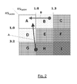
- FIG. 2 shows the saturation matrix wherein, by way of example, corrective actions of critical operating conditions are illustrated.
- a ZLD system provides for the combustion flue gas to be treated to lower SO x in a conventional DeSOx plant and for the liquid stream coming from them to be treated in a DeSOx waste treatment unit (i.e. Treatment-Storage-Disposal or TSD), as already briefly described.
- a DeSOx waste treatment unit i.e. Treatment-Storage-Disposal or TSD
- a fraction 1 of the liquid stream coming out from the DeSOx waste treatment unit TSD is sent to a storage tank SA, while the remaining fraction 2 is sent to an evaporation SEC (Softening-Evaporation-Crystallization) plant, also already briefly described.
- a dehydrated solid (Moisture ⁇ 25%) for disposal in a landfill, indicated as 3 , and a liquid stream 4 sent to the storage tank SA, comes out.
- the stream 4 comprises the distillate produced during the evaporation/crystallization (EC) and the fraction of non-evaporated softened water recovered directly in the tank SA.
- the liquid wastes 5 of the productive plant IP and the sewer waters of toilets flow into the latter tank upon treatment in the treatment plant for liquid waste (ITAR).
- a make-up low-salinity water 7 coming from external sources R such as wells, consortia, public waterworks, etc., is sent to the tank SA, and to the productive plant IP.
- the water collected in the storage tank SA is fed (stream 6 ) to the DeSOx plant.
- critical sections some sections of the ZLD system, hereinafter referred to as “critical sections”, have been identified, wherein the localized saturation of calcium salts has had a higher relevance and impact on the functioning of the thermoelectric units.
- Table 2 hereunder lists the critical sections with the indication of the degree of saturation of calcium sulphate and calcium carbonate, i.e. those salts which have shown the greater tendency to precipitate in an uncontrolled manner.
- the evaluation of the saturation degree is accomplished by evaluating the saturation ratios calculated as follows:
- the saturation ratios provide an indication of the scaling potential of waters in operating conditions with reference to the compound for which it is calculated.
- the critical sections SC 1 -SC 4 shown above are also indicated in FIG. 1 .
- the dosage of calcium hydroxide in the treatment plant for desulfurizing wastes can be set to the minimum necessary level to ensure that the precipitation of earth-alkaline metals does not exceed the limit value of 1.3 for the calcium sulphate saturation ratio.
- the dosage of sodium carbonate provided in the softening step drastically reduces the saturation ratio for calcium sulphate (even much lower than 0.5) but can make it difficult to control the precipitation of the calcium carbonate because of increased alkalinity, to which saturation ratios values for calcium carbonate can correspond, which are even higher than 5.
- Such phenomenon can be worsened by mixing softened water, containing a certain residual alkalinity, with the liquid waste coming out from the treatment for desulfurizing wastes TSD, having high concentrations of calcium. This can possibly occur in the presence of a softening by-pass, whose admixture with softened water, before being sent to evaporation, causes the onset of substantial phenomena of precipitation of calcium carbonate.
- FIG. 2 the thresholds of the saturation ratios of calcium sulphate and calcium carbonate are represented in a matrix way (saturation matrix). Inside the matrix, solutions paths for some of the critical sections of Table 2, which can be obtained by means of the above mentioned corrective actions, are reported by way of example.
- the arrows show the passage from the initial chemical condition, related to the first running of the system, to the final comfort condition, wherein both RS values are lower than 1.
- letter A represents the evolution of the RS for the feeding of the evaporating stage (SC 3 ) which shows a critical situation of first exercise connected to the precipitation of calcium carbonate, which can be solved by using the method described above.
- letter B shows an initial critical situation for the precipitation of calcium sulphate in the DeSOx pre-scrubbers (SC 4 ), which can again be solved by using the method described above.
- the ZLD process in power plants does not produce any liquid waste for emission into surface waters, including ocean, sea, river and lake waters, and the discharge to surface waters in the present ZLD system may be closed, as clearly shown in FIG. 1 .
Landscapes
- Chemical & Material Sciences (AREA)
- Organic Chemistry (AREA)
- Engineering & Computer Science (AREA)
- Environmental & Geological Engineering (AREA)
- Water Supply & Treatment (AREA)
- Hydrology & Water Resources (AREA)
- Life Sciences & Earth Sciences (AREA)
- Chemical Kinetics & Catalysis (AREA)
- Treating Waste Gases (AREA)
- Cultivation Of Plants (AREA)
- Inorganic Compounds Of Heavy Metals (AREA)
- Removal Of Specific Substances (AREA)
- Nitrogen And Oxygen Or Sulfur-Condensed Heterocyclic Ring Systems (AREA)
Abstract
Description
| TABLE 1 | |||
| pH | 4-6.5 | ||
| Ca++ [mg/L] | 1.000-15.000 | ||
| Mg++ [mg/L] | 50-1.500 | ||
| Na+ [mg/L] | 300-1.500 | ||
| Cl− [mg/L] | 1.200-30.000 | ||
| SO4 −− [mg/L] | 1.000-6.000 | ||
| NO3 − [mg/L] | 50-1.000 | ||
| F− [mg/L] | 10-30 | ||
| NH4 + [mg/L] | 10-100 | ||
| SiO2 [mg/L] | 5-20 | ||
| TDS [mg/L] | 10.000-50.000 | ||
-
- [Ca++] and [SO4=] are the measured concentrations;
- Kps is the constant of solubility at the temperature of measure;
-
- pH is the measured pH;
- pHs is the saturation pH.
- The difference pH-pHs is the Langelier index.
| TABLE 2 | ||
| Saturation of | Saturation of | |
| calcium | calcium | |
| Stream | sulphate | carbonate |
| Outlet of the DeSOx waste | Potentially high | Usually low |
| treatment plant (SC1) | ||
| Outlet of the DeSOx waste | Usually low | Potentially high |
| softening (SC2) | ||
| Feeding of the evaporation step of | Potentially relevant | Potentially high |
| SEC (SC3) | ||
| DeSOx make-up from the storage | Potentially high | Potentially high |
| tank (SC4) | ||
Claims (7)
Applications Claiming Priority (4)
| Application Number | Priority Date | Filing Date | Title |
|---|---|---|---|
| ITFI2011A000063 | 2011-04-08 | ||
| ITFI2011A0063 | 2011-04-08 | ||
| IT000063A ITFI20110063A1 (en) | 2011-04-08 | 2011-04-08 | METHOD FOR THE MONITORING AND CONTROL OF THE CHEMISTRY OF A ZLD PROCESS APPLIED TO POWER PLANTS |
| PCT/IB2012/051724 WO2012137183A1 (en) | 2011-04-08 | 2012-04-06 | A method for monitoring and controlling the chemistry of a zld process in power plants |
Publications (2)
| Publication Number | Publication Date |
|---|---|
| US20140054230A1 US20140054230A1 (en) | 2014-02-27 |
| US8877066B2 true US8877066B2 (en) | 2014-11-04 |
Family
ID=44553917
Family Applications (1)
| Application Number | Title | Priority Date | Filing Date |
|---|---|---|---|
| US14/110,416 Active US8877066B2 (en) | 2011-04-08 | 2012-04-06 | Method for monitoring and controlling the chemistry of a ZLD process in power plants |
Country Status (22)
| Country | Link |
|---|---|
| US (1) | US8877066B2 (en) |
| EP (1) | EP2694441B1 (en) |
| JP (1) | JP5965473B2 (en) |
| CN (1) | CN103502154B (en) |
| AU (1) | AU2012241006B2 (en) |
| BR (1) | BR112013025924B1 (en) |
| CA (1) | CA2832014A1 (en) |
| CL (1) | CL2013002848A1 (en) |
| CY (1) | CY1116329T1 (en) |
| DK (1) | DK2694441T3 (en) |
| ES (1) | ES2534974T3 (en) |
| HR (1) | HRP20150441T1 (en) |
| IL (1) | IL228783A (en) |
| IT (1) | ITFI20110063A1 (en) |
| PL (1) | PL2694441T3 (en) |
| PT (1) | PT2694441E (en) |
| RS (1) | RS53943B1 (en) |
| RU (1) | RU2602131C2 (en) |
| SI (1) | SI2694441T1 (en) |
| SM (1) | SMT201500096B (en) |
| WO (1) | WO2012137183A1 (en) |
| ZA (1) | ZA201308281B (en) |
Cited By (3)
| Publication number | Priority date | Publication date | Assignee | Title |
|---|---|---|---|---|
| US9724638B2 (en) | 2014-01-02 | 2017-08-08 | General Electric Technology Gmbh | Apparatus and method for evaporating waste water and reducing acid gas emissions |
| US9861930B2 (en) | 2014-01-02 | 2018-01-09 | General Electric Technology Gmbh | Apparatus and method for evaporating waste water and reducing acid gas emissions |
| US10350542B2 (en) | 2016-04-29 | 2019-07-16 | General Electric Company | Wet flue gas desulfurization system with zero waste water liquid discharge |
Families Citing this family (1)
| Publication number | Priority date | Publication date | Assignee | Title |
|---|---|---|---|---|
| CN102992427B (en) * | 2012-12-12 | 2013-09-04 | 众和海水淡化工程有限公司 | Wastewater zero-discharge treatment system |
Citations (2)
| Publication number | Priority date | Publication date | Assignee | Title |
|---|---|---|---|---|
| EP0302522A2 (en) | 1987-08-07 | 1989-02-08 | Nalco Chemical Company | Method and additive for monitoring circuit water hardness in conversion plants |
| EP1110595A1 (en) | 1999-12-23 | 2001-06-27 | Dravo Lime, Inc. | Reduction of calcium and chloride in the flue gas desulfurization process |
Family Cites Families (16)
| Publication number | Priority date | Publication date | Assignee | Title |
|---|---|---|---|---|
| JPS51102357A (en) * | 1975-03-07 | 1976-09-09 | Ebara Infilco | HAISUISHORIHOHO |
| JPS53104593A (en) * | 1977-02-25 | 1978-09-11 | Kawasaki Steel Co | Method of preventing scale production in recycling system for cooling blast furnace slag |
| SU1028608A1 (en) * | 1980-12-17 | 1983-07-15 | Донецкий Филиал Всесоюзного Научно-Исследовательского И Проектного Института По Очистке Технологических Газов,Сточных Вод И Использованию Вторичных Энергоресурсов Предприятий Черной Металлургии | Method for purifying acid effluents |
| JPS6058230A (en) * | 1983-09-09 | 1985-04-04 | Babcock Hitachi Kk | Waste gas desulfurization and apparatus thereof |
| JP2886180B2 (en) * | 1989-06-05 | 1999-04-26 | バブコツク日立株式会社 | Wastewater treatment method for wet desulfurization equipment |
| JP2940981B2 (en) * | 1990-02-26 | 1999-08-25 | バブコツク日立株式会社 | Wet exhaust gas desulfurization apparatus and wet exhaust gas desulfurization method |
| JPH07256050A (en) * | 1994-03-24 | 1995-10-09 | Chiyoda Corp | Wet flue gas desulfurization equipment no drainage method |
| RU2074122C1 (en) * | 1994-09-29 | 1997-02-27 | Московский энергетический институт | Method of thermally desalting water |
| JP3526975B2 (en) * | 1995-07-21 | 2004-05-17 | バブコック日立株式会社 | Coal ash solidification treatment method for desulfurization wastewater |
| JP2944939B2 (en) * | 1996-09-12 | 1999-09-06 | 川崎重工業株式会社 | Desulfurization wastewater treatment method and apparatus |
| RU2137722C1 (en) * | 1998-07-13 | 1999-09-20 | Московский энергетический институт (Технический университет) | Method for thermochemical desalting of natural and waste waters |
| JP2000314557A (en) * | 1999-04-28 | 2000-11-14 | Toto Ltd | Water heater |
| US7117046B2 (en) * | 2004-08-27 | 2006-10-03 | Alstom Technology Ltd. | Cascaded control of an average value of a process parameter to a desired value |
| JP4737670B2 (en) * | 2005-03-30 | 2011-08-03 | 株式会社ササクラ | Method and apparatus for treating wastewater containing calcium and sulfuric acid |
| CN101891330B (en) * | 2010-07-23 | 2012-09-05 | 深圳市能源环保有限公司 | Power plant wastewater treatment system and method |
| CN102060408B (en) * | 2010-12-07 | 2012-06-06 | 华电水处理技术工程有限公司 | Wastewater evaporating process and device system |
-
2011
- 2011-04-08 IT IT000063A patent/ITFI20110063A1/en unknown
-
2012
- 2012-04-06 SI SI201230189T patent/SI2694441T1/en unknown
- 2012-04-06 CN CN201280017300.XA patent/CN103502154B/en active Active
- 2012-04-06 ES ES12718386.1T patent/ES2534974T3/en active Active
- 2012-04-06 JP JP2014503269A patent/JP5965473B2/en active Active
- 2012-04-06 DK DK12718386.1T patent/DK2694441T3/en active
- 2012-04-06 RU RU2013149869/05A patent/RU2602131C2/en active
- 2012-04-06 EP EP12718386.1A patent/EP2694441B1/en active Active
- 2012-04-06 PT PT127183861T patent/PT2694441E/en unknown
- 2012-04-06 RS RS20150263A patent/RS53943B1/en unknown
- 2012-04-06 BR BR112013025924A patent/BR112013025924B1/en not_active IP Right Cessation
- 2012-04-06 CA CA2832014A patent/CA2832014A1/en not_active Abandoned
- 2012-04-06 US US14/110,416 patent/US8877066B2/en active Active
- 2012-04-06 HR HRP20150441TT patent/HRP20150441T1/en unknown
- 2012-04-06 WO PCT/IB2012/051724 patent/WO2012137183A1/en not_active Ceased
- 2012-04-06 PL PL12718386T patent/PL2694441T3/en unknown
- 2012-04-06 AU AU2012241006A patent/AU2012241006B2/en active Active
-
2013
- 2013-10-04 CL CL2013002848A patent/CL2013002848A1/en unknown
- 2013-10-08 IL IL228783A patent/IL228783A/en active IP Right Grant
- 2013-11-05 ZA ZA2013/08281A patent/ZA201308281B/en unknown
-
2015
- 2015-04-16 SM SM201500096T patent/SMT201500096B/en unknown
- 2015-04-21 CY CY20151100368T patent/CY1116329T1/en unknown
Patent Citations (2)
| Publication number | Priority date | Publication date | Assignee | Title |
|---|---|---|---|---|
| EP0302522A2 (en) | 1987-08-07 | 1989-02-08 | Nalco Chemical Company | Method and additive for monitoring circuit water hardness in conversion plants |
| EP1110595A1 (en) | 1999-12-23 | 2001-06-27 | Dravo Lime, Inc. | Reduction of calcium and chloride in the flue gas desulfurization process |
Non-Patent Citations (4)
| Title |
|---|
| PCT International Preliminary Report on Patentability completed on Aug. 14, 2013 for PCT Application PCT/IB2012/051724 filed on Apr. 6, 2012 in the name of Enel Produzione S.P.A. |
| PCT International Search Report mailed on Jun. 13, 2012 for PCT Application PCT/IB2012/051724 filed on Apr. 6, 2012 in the name of Enel Produzione S.P.A. |
| PCT Written Opinion mailed on Jun. 13, 2012 for PCT Application PCT/IB2012/051724 filed on Apr. 6, 2012 in the name of Enel Produzione S.P.A. |
| Siegworth, A., et al., Case study: Integrating membrane processes with evaporation to achieve economical zero liquid discharge at the Doswell Combined Cycle Facility, Desalination 1995, 102: 81-86. |
Cited By (3)
| Publication number | Priority date | Publication date | Assignee | Title |
|---|---|---|---|---|
| US9724638B2 (en) | 2014-01-02 | 2017-08-08 | General Electric Technology Gmbh | Apparatus and method for evaporating waste water and reducing acid gas emissions |
| US9861930B2 (en) | 2014-01-02 | 2018-01-09 | General Electric Technology Gmbh | Apparatus and method for evaporating waste water and reducing acid gas emissions |
| US10350542B2 (en) | 2016-04-29 | 2019-07-16 | General Electric Company | Wet flue gas desulfurization system with zero waste water liquid discharge |
Also Published As
| Publication number | Publication date |
|---|---|
| AU2012241006A1 (en) | 2013-10-17 |
| US20140054230A1 (en) | 2014-02-27 |
| BR112013025924A2 (en) | 2016-12-20 |
| AU2012241006B2 (en) | 2016-09-15 |
| EP2694441B1 (en) | 2015-01-28 |
| SI2694441T1 (en) | 2015-06-30 |
| JP2014516308A (en) | 2014-07-10 |
| IL228783A (en) | 2017-01-31 |
| IL228783A0 (en) | 2013-12-31 |
| CL2013002848A1 (en) | 2014-04-11 |
| ZA201308281B (en) | 2014-08-27 |
| SMT201500096B (en) | 2015-07-09 |
| PT2694441E (en) | 2015-05-13 |
| JP5965473B2 (en) | 2016-08-03 |
| RU2013149869A (en) | 2015-05-20 |
| BR112013025924B1 (en) | 2020-04-28 |
| CN103502154B (en) | 2015-11-25 |
| DK2694441T3 (en) | 2015-04-13 |
| RU2602131C2 (en) | 2016-11-10 |
| ITFI20110063A1 (en) | 2012-10-09 |
| CN103502154A (en) | 2014-01-08 |
| CA2832014A1 (en) | 2012-10-11 |
| PL2694441T3 (en) | 2015-06-30 |
| CY1116329T1 (en) | 2017-02-08 |
| ES2534974T3 (en) | 2015-04-30 |
| RS53943B1 (en) | 2015-08-31 |
| WO2012137183A1 (en) | 2012-10-11 |
| EP2694441A1 (en) | 2014-02-12 |
| HRP20150441T1 (en) | 2015-05-22 |
Similar Documents
| Publication | Publication Date | Title |
|---|---|---|
| Epsztein et al. | Selective nitrate removal from groundwater using a hybrid nanofiltration–reverse osmosis filtration scheme | |
| Cui et al. | Electrolysis-electrodialysis process for removing chloride ion in wet flue gas desulfurization wastewater (DW): influencing factors and energy consumption analysis | |
| CN105565573A (en) | Device and method for desulfurization waste water zero discharge treatment | |
| CN110668540A (en) | A kind of high-salt wastewater precipitation and desalination recycling process | |
| CN106830479A (en) | Using flue gas and electrodialytic desulfurization wastewater zero-discharge treatment system and method | |
| CN106746016A (en) | A kind of method and apparatus for processing waste water | |
| US8877066B2 (en) | Method for monitoring and controlling the chemistry of a ZLD process in power plants | |
| CN105540960A (en) | Treatment method and treatment system for wastewater produced during flue gas desulfurization adopting limestone/lime-gypsum method | |
| EP2649013A1 (en) | High efficiency water purification system | |
| AU2013315460A1 (en) | Method and system for treating produced water | |
| CN107721037A (en) | A kind of high ammonia nitrogen desulfurization wastewater processing up to standard and reclaiming system and method | |
| Migliorini et al. | Seawater reverse osmosis plant using the pressure exchanger for energy recovery: a calculation model | |
| CN107089744A (en) | A kind of method of desulfurization wastewater advanced treating zero-emission | |
| CN106746059B (en) | Terminal high salt wastewater treatment system of economical coal fired power plant | |
| CN207567040U (en) | A kind of processing up to standard of high ammonia nitrogen desulfurization wastewater and reclaiming system | |
| CN105347592B (en) | A kind of recycling and zero discharge treatment process of desulfurization wastewater | |
| CN108203193A (en) | A kind of cooling cycle wastewater recycling process | |
| CN104016510B (en) | The Application way of a kind of thermal power plant reverse osmosis concentrated water and municipal effluent interaction process | |
| CN117776455A (en) | Wet desulfurization wastewater treatment system and method for waste incineration power plant | |
| CN210193565U (en) | A zero-discharge system for waste water in the whole plant of reclaimed water source gas-fired power plants | |
| CN212292942U (en) | Desulfurization wastewater concentration decrement processing system based on directional driving electrodialysis technology | |
| CN211393976U (en) | High-salinity wastewater precipitation desalination cyclic utilization system | |
| CN113461237A (en) | Zero discharge system for salt wastewater treatment | |
| Gardoni et al. | Reuse of process water in a waste-to-energy plant: An Italian case of study | |
| CN206089336U (en) | Zero discharging equipment of sewage recycling |
Legal Events
| Date | Code | Title | Description |
|---|---|---|---|
| AS | Assignment |
Owner name: ENEL PRODUZIONE S.P.A., ITALY Free format text: ASSIGNMENT OF ASSIGNORS INTEREST;ASSIGNORS:CENCI, VINCENZO;MOSTI, CLAUDIO;REEL/FRAME:031621/0744 Effective date: 20131016 |
|
| STCF | Information on status: patent grant |
Free format text: PATENTED CASE |
|
| FEPP | Fee payment procedure |
Free format text: PAYOR NUMBER ASSIGNED (ORIGINAL EVENT CODE: ASPN); ENTITY STATUS OF PATENT OWNER: LARGE ENTITY |
|
| MAFP | Maintenance fee payment |
Free format text: PAYMENT OF MAINTENANCE FEE, 4TH YEAR, LARGE ENTITY (ORIGINAL EVENT CODE: M1551) Year of fee payment: 4 |
|
| FEPP | Fee payment procedure |
Free format text: MAINTENANCE FEE REMINDER MAILED (ORIGINAL EVENT CODE: REM.); ENTITY STATUS OF PATENT OWNER: LARGE ENTITY |
|
| FEPP | Fee payment procedure |
Free format text: 7.5 YR SURCHARGE - LATE PMT W/IN 6 MO, LARGE ENTITY (ORIGINAL EVENT CODE: M1555); ENTITY STATUS OF PATENT OWNER: LARGE ENTITY |
|
| MAFP | Maintenance fee payment |
Free format text: PAYMENT OF MAINTENANCE FEE, 8TH YEAR, LARGE ENTITY (ORIGINAL EVENT CODE: M1552); ENTITY STATUS OF PATENT OWNER: LARGE ENTITY Year of fee payment: 8 |