US8875518B2 - Nacelle with an adaptable outlet section - Google Patents
Nacelle with an adaptable outlet section Download PDFInfo
- Publication number
- US8875518B2 US8875518B2 US12/674,237 US67423708A US8875518B2 US 8875518 B2 US8875518 B2 US 8875518B2 US 67423708 A US67423708 A US 67423708A US 8875518 B2 US8875518 B2 US 8875518B2
- Authority
- US
- United States
- Prior art keywords
- nacelle
- outlet section
- exhaust nozzle
- fixed structure
- engine compartment
- Prior art date
- Legal status (The legal status is an assumption and is not a legal conclusion. Google has not performed a legal analysis and makes no representation as to the accuracy of the status listed.)
- Expired - Fee Related, expires
Links
Images


Classifications
-
- B—PERFORMING OPERATIONS; TRANSPORTING
- B64—AIRCRAFT; AVIATION; COSMONAUTICS
- B64D—EQUIPMENT FOR FITTING IN OR TO AIRCRAFT; FLIGHT SUITS; PARACHUTES; ARRANGEMENT OR MOUNTING OF POWER PLANTS OR PROPULSION TRANSMISSIONS IN AIRCRAFT
- B64D33/00—Arrangement in aircraft of power plant parts or auxiliaries not otherwise provided for
- B64D33/04—Arrangement in aircraft of power plant parts or auxiliaries not otherwise provided for of exhaust outlets or jet pipes
-
- B—PERFORMING OPERATIONS; TRANSPORTING
- B64—AIRCRAFT; AVIATION; COSMONAUTICS
- B64D—EQUIPMENT FOR FITTING IN OR TO AIRCRAFT; FLIGHT SUITS; PARACHUTES; ARRANGEMENT OR MOUNTING OF POWER PLANTS OR PROPULSION TRANSMISSIONS IN AIRCRAFT
- B64D29/00—Power-plant nacelles, fairings or cowlings
- B64D29/06—Attaching of nacelles, fairings or cowlings
-
- F—MECHANICAL ENGINEERING; LIGHTING; HEATING; WEAPONS; BLASTING
- F02—COMBUSTION ENGINES; HOT-GAS OR COMBUSTION-PRODUCT ENGINE PLANTS
- F02K—JET-PROPULSION PLANTS
- F02K1/00—Plants characterised by the form or arrangement of the jet pipe or nozzle; Jet pipes or nozzles peculiar thereto
- F02K1/06—Varying effective area of jet pipe or nozzle
- F02K1/08—Varying effective area of jet pipe or nozzle by axially moving or transversely deforming an internal member, e.g. the exhaust cone
- F02K1/085—Varying effective area of jet pipe or nozzle by axially moving or transversely deforming an internal member, e.g. the exhaust cone by transversely deforming an internal member
-
- Y—GENERAL TAGGING OF NEW TECHNOLOGICAL DEVELOPMENTS; GENERAL TAGGING OF CROSS-SECTIONAL TECHNOLOGIES SPANNING OVER SEVERAL SECTIONS OF THE IPC; TECHNICAL SUBJECTS COVERED BY FORMER USPC CROSS-REFERENCE ART COLLECTIONS [XRACs] AND DIGESTS
- Y10—TECHNICAL SUBJECTS COVERED BY FORMER USPC
- Y10T—TECHNICAL SUBJECTS COVERED BY FORMER US CLASSIFICATION
- Y10T137/00—Fluid handling
- Y10T137/0536—Highspeed fluid intake means [e.g., jet engine intake]
Definitions
- the disclosure relates to a jet engine nacelle for an aircraft.
- An aircraft is propelled by two or more turbojets, each housed in a nacelle which also encloses a series of associated activating devices connected to its operation and performing various functions when the turbojet is running or stopped.
- These associated activating devices may include in particular a mechanical system for operating thrust reversers.
- a nacelle usually has a tubular structure comprising an air inlet forward of the turbojet, a middle section designed to surround a fan of the turbojet, and a rear section which encloses thrust reverser means, is designed to surround the turbojet combustion chamber, and usually ends in an exhaust nozzle whose outlet is situated downstream of the turbojet.
- Modern nacelles are often designed to enclose a turbofan capable of generating by means of the blades of the rotating fan a hot airflow (also called the primary flow) leaving the turbojet combustion chamber.
- a nacelle usually has an outer fixed structure (OFS), which defines, with an inner concentric structure of the rear section, termed the inner fixed structure (IFS), surrounding the structure of the turbojet proper to the rear of the fan, an annular flow channel, also termed the secondary stream, designed to channel a secondary flow of cold air around the outside of the turbojet.
- OFS outer fixed structure
- IFS inner fixed structure
- the fixed inner structure and the exhaust nozzle define an engine compartment ventilation outlet section whose main purpose is to renew the air flowing between the IFS and the engine, but which can be used to recover some of the thrust lost by the air taken from the secondary stream by controlling the geometry of the cross-sectional area of the airflow.
- spacer means in the form of rigid spacers are positioned in the outlet section and held in place by belting.
- the turbojet In flight, however, the turbojet has a tendency to twist, in a different way from the nacelle. This causes very large loadings of said engine compartment on the nacelle.
- a nacelle for a turbojet comprising a rear section having an inner fixed structure designed to surround a rear part of an engine compartment and to define, with an exhaust nozzle, a calibrated outlet section for the ventilation of the engine compartment using spacer means located in the outlet section, characterized in that the spacer means are divided into rigid spacer means designed to provide a constant gap, and compensating means designed to be able to adapt to the relative movements of the turbojet with respect to the nacelle.
- the decoupling of the spacer means in this way makes it possible to greatly limit the stresses the nacelle has to withstand owing to the deformation of the turbojet.
- the compensating means are, in an exemplary embodiment, attached to the rigid spacer means.
- the compensating means are, in an exemplary embodiment, also designed to form a valve. This is a considerable advantage inasmuch as the spacer means will therefore be able to adapt to a pressure increase occurring in the engine compartment.
- the compensating means will therefore be able to be arranged in such a way as to retract under the action of this pressure increase, so that an extra passage will be opened in order to increase the exhausted airflow.
- the rigid spacer means are fixed inside the inner fixed structure.
- the rigid spacer means are fixed inside the exhaust nozzle.
- the rigid spacer means advantageously comprise a plurality of U-shaped elements forming spacers distributed around the periphery of the outlet section.
- the compensating means comprise a plurality of elements having a first end attached to the rigid spacer means, and a free second end.
- the compensating means are, in an exemplary embodiment, made in the form of a ring comprising a plurality of longitudinal slots forming longitudinal fingers.
- each element is pressed against the exhaust nozzle.
- the free second end of each element is pressed against the inner fixed structure.
- the disclosure also relates to an aircraft characterized in that it comprises at least one nacelle according to the disclosure.
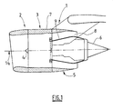
- FIG. 1 is a schematic view in longitudinal section of a nacelle according to an embodiment in a closed state
- FIG. 2 is an enlarged diagrammatic perspective view from the rear of the nacelle shown in FIG. 1 ;
- FIG. 3 is an enlarged schematic view of the outlet section from the rear of the nacelle shown in FIG. 2 ;
- FIG. 4 is a partial schematic view from the front of the outlet section shown in FIG. 3 ;
- FIG. 5 is a schematic view in longitudinal section of the outlet section of the nacelle shown in FIG. 1 ;
- FIG. 6 is a schematic view similar to FIG. 5 , during a pressure increase in the combustion chamber of the turbojet.
- a nacelle 1 of an aircraft comprises in a manner known per se a front air inlet section 2 , a middle section 3 designed to surround the fan 4 , and a rear section 5 designed to surround an engine compartment (not shown), ending in an exhaust nozzle 6 whose outlet is situated to the rear of the turbojet.
- This nacelle 1 comprises an outer fixed structure, or OFS, 7 which defines an annular flow channel 8 with a concentric inner fixed structure, or IFS, 9 surrounding the structure of the turbojet proper to the rear of the fan 4 .
- the inner fixed structure 9 and the exhaust nozzle 6 define an outlet section 10 for the ventilation of the engine compartment, which can be used to recover some of the thrust lost by the air taken from the annular channel 8 by controlling the geometry of the cross-sectional area of the airflow.
- spacer means made of metal, particularly titanium, are arranged in the outlet section 10 .
- spacer means are divided into rigid spacer means 11 , 12 designed to provide a constant gap, and compensating means 13 designed to be able to adapt to the relative movements between the turbojet and the nacelle 1 .
- the rigid spacer means 11 , 12 are made from a plurality of U-section elements forming spacers.
- the rigid spacer means 11 are arranged in such a way that the free arms of the U are parallel to the axis 14 of the nacelle 1 , and directed forward.
- the rigid spacer means 12 are positioned in such a way as to be positioned in a plane normal to the axis 14 of the nacelle 1 as shown in FIGS. 1 through 4 .
- the rigid spacer means 11 , 12 are uniformly distributed in one plane around the periphery of the outlet section 10 , in such a way that one rigid spacer means 12 is inserted between two rigid spacer means 11 , as shown more especially in FIGS. 3 and 4 .
- the rigid spacer means 11 , 12 are each riveted in the inner fixed structure 9 , as shown schematically in FIG. 5 under reference 20 .
- the spaces between the various rigid spacer means 11 consequently define passages allowing calibrated ventilation at the outlet section 10 .
- each rigid spacer means 12 which also defines a passage allowing calibrated ventilation at the outlet section 10 .
- the compensating means 13 are made in the form of a ring 15 comprising a plurality of longitudinal slots 16 forming longitudinal fingers 17 parallel to the axis 14 .
- This ring 15 is fixed with rivets 18 in each of the rigid spacer means 11 , 12 at the forward end of each finger 17 , and the free rear end of the latter presses on the outside face of the exhaust nozzle 6 .
- the spacer means 11 thus have in particular the function of forming stops in the event of large relative movements of the engine with respect to the nacelle 1 , in addition to keeping the forward end of each finger 17 in position.
- the spacer means 12 meanwhile have the function of keeping the forward end of each finger 17 in position without obstructing the ventilation outlet 10 .
- each finger 17 comprises schematically a first or forward portion 17 a connected to a second or rear portion 17 b by an elbow 19 .
- This finger 17 is designed in such a way that, once the ring 15 is fixed in the rigid spacer means 11 , 12 , the second portion 17 b has to be moved radially away in order to be able to press it against the exhaust nozzle 6 . Each finger 17 is therefore constantly in tension, as the second portion 17 b attempts to recover its rest position shown schematically in chain lines in FIG. 5 .
- these fingers 17 are designed in such a way as to form a valve. This is a considerable advantage inasmuch as the compensating means 13 can therefore adapt to a pressure increase occurring in the engine compartment, as shown in FIG. 6 .
- the second portion 17 b of each finger 17 is able to move radially away from the exhaust nozzle 6 under the force of this pressure increase, and therefore a supplementary passage, indicated by the arrow, is opened up in order to increase the exhausted airflow.
Landscapes
- Engineering & Computer Science (AREA)
- Aviation & Aerospace Engineering (AREA)
- Chemical & Material Sciences (AREA)
- Combustion & Propulsion (AREA)
- Mechanical Engineering (AREA)
- Structures Of Non-Positive Displacement Pumps (AREA)
- Supercharger (AREA)
Abstract
Description
Claims (9)
Applications Claiming Priority (3)
| Application Number | Priority Date | Filing Date | Title |
|---|---|---|---|
| FR0705920A FR2920146B1 (en) | 2007-08-20 | 2007-08-20 | NACELLE WITH ADAPTABLE OUTPUT SECTION |
| FR0705920 | 2007-08-20 | ||
| PCT/FR2008/000859 WO2009024660A1 (en) | 2007-08-20 | 2008-06-19 | Nacelle with an adaptable outlet section |
Publications (2)
| Publication Number | Publication Date |
|---|---|
| US20110214747A1 US20110214747A1 (en) | 2011-09-08 |
| US8875518B2 true US8875518B2 (en) | 2014-11-04 |
Family
ID=39204058
Family Applications (1)
| Application Number | Title | Priority Date | Filing Date |
|---|---|---|---|
| US12/674,237 Expired - Fee Related US8875518B2 (en) | 2007-08-20 | 2008-06-19 | Nacelle with an adaptable outlet section |
Country Status (8)
| Country | Link |
|---|---|
| US (1) | US8875518B2 (en) |
| EP (1) | EP2181041A1 (en) |
| CN (1) | CN101784449B (en) |
| BR (1) | BRPI0813603A2 (en) |
| CA (1) | CA2696792C (en) |
| FR (1) | FR2920146B1 (en) |
| RU (1) | RU2469923C2 (en) |
| WO (1) | WO2009024660A1 (en) |
Cited By (3)
| Publication number | Priority date | Publication date | Assignee | Title |
|---|---|---|---|---|
| US20220268212A1 (en) * | 2019-08-16 | 2022-08-25 | Safran Aircraft Engines | Internal structure for a turbomachine nacelle |
| US11542026B2 (en) * | 2017-12-21 | 2023-01-03 | Safran Nacelles | Aircraft propulsion unit and method for ventilating an engine enclosure |
| US11685539B2 (en) * | 2019-09-27 | 2023-06-27 | Rohr, Inc. | Passive internal compartment exhaust for an aircraft propulsion system |
Families Citing this family (7)
| Publication number | Priority date | Publication date | Assignee | Title |
|---|---|---|---|---|
| FR2966435B1 (en) * | 2010-10-25 | 2013-04-26 | Aircelle Sa | TURBO-BASE TRAILER WITH ADAPTABLE VENTILATION OUTPUT SECTION |
| WO2012125895A1 (en) * | 2011-03-17 | 2012-09-20 | Bombardier Inc. | System and method for operating a precooler in an aircraft |
| FR2978989B1 (en) * | 2011-08-12 | 2013-07-26 | Aircelle Sa | EJECTION CONE FOR AIRCRAFT TURBOJET ENGINE |
| US10294863B2 (en) | 2013-07-09 | 2019-05-21 | United Technologies Corporation | Preloaded AFT vent area for low pressure fan ducts |
| WO2016027187A1 (en) | 2014-08-20 | 2016-02-25 | Bombardier Inc. | Actuated outlet door for aircraft high-temperature exhaust |
| US11518535B2 (en) * | 2019-09-30 | 2022-12-06 | Rohr, Inc. | Nacelle cowl deflection limiter |
| FR3103226B1 (en) * | 2019-11-15 | 2021-11-12 | Airbus Operations Sas | AIRCRAFT TURBOMACHINE WITH A PRIMARY TUBE EQUIPPED WITH A WEAR SHIM |
Citations (31)
| Publication number | Priority date | Publication date | Assignee | Title |
|---|---|---|---|---|
| US3263417A (en) * | 1963-10-02 | 1966-08-02 | Bristol Siddeley Engines Ltd | Jet propulsion nozzle |
| US3598318A (en) * | 1970-04-10 | 1971-08-10 | Boeing Co | Movable acoustic splitter for nozzle area control and thrust reversal |
| US3721389A (en) * | 1971-06-10 | 1973-03-20 | Boeing Co | Exit nozzle assemblies for gas turbine power plants |
| US3750983A (en) * | 1970-08-11 | 1973-08-07 | Rolls Royce | Gas turbine ducted fan engines for aircraft |
| US3964257A (en) * | 1974-02-11 | 1976-06-22 | Societe Nationale D'etude Et De Construction De Moteurs D'aviation | Device for boosting and bleeding a gas turbine engine |
| US4232513A (en) * | 1977-10-19 | 1980-11-11 | Rolls-Royce Limited | Pressure relief panel for aircraft powerplant |
| US4271666A (en) * | 1979-08-20 | 1981-06-09 | Avco Corporation | Integral infrared radiation suppressor for a turbofan engine |
| US4825644A (en) * | 1987-11-12 | 1989-05-02 | United Technologies Corporation | Ventilation system for a nacelle |
| US4961588A (en) * | 1989-01-31 | 1990-10-09 | Westinghouse Electric Corp. | Radial seal |
| US5054281A (en) * | 1989-09-25 | 1991-10-08 | Rohr Industries, Inc. | Gas turbine engine compartment vent system |
| US5110050A (en) * | 1974-09-07 | 1992-05-05 | Rolls-Royce (1971) Limited | Gas turbine engine nozzle |
| US5174525A (en) * | 1991-09-26 | 1992-12-29 | General Electric Company | Structure for eliminating lift load bending in engine core of turbofan |
| US5524846A (en) * | 1993-12-21 | 1996-06-11 | The Boeing Company | Fire protection system for airplanes |
| US5577381A (en) * | 1994-12-06 | 1996-11-26 | United Technologies Corporation | Exhaust nozzle cooling scheme for gas turbine engine |
| US5632493A (en) * | 1995-05-04 | 1997-05-27 | Eg&G Sealol, Inc. | Compliant pressure balanced seal apparatus |
| US5704207A (en) | 1995-02-03 | 1998-01-06 | The Boeing Company | Flow control apparatus for gas turbine engine installation pressure relief doors |
| US5729969A (en) * | 1995-05-15 | 1998-03-24 | Aerospatiale Societe Nationale Industrielle | Device for bleeding off and cooling hot air in an aircraft engine |
| US5778659A (en) * | 1994-10-20 | 1998-07-14 | United Technologies Corporation | Variable area fan exhaust nozzle having mechanically separate sleeve and thrust reverser actuation systems |
| EP0867366A2 (en) | 1997-03-28 | 1998-09-30 | The Boeing Company | Segmented engine flow control device |
| US5906097A (en) * | 1997-03-28 | 1999-05-25 | The Boeing Company | Engine flow control device |
| US6070407A (en) * | 1996-01-04 | 2000-06-06 | Rolls-Royce Plc | Ducted fan gas turbine engine with variable area fan duct nozzle |
| US20030126856A1 (en) * | 2001-10-23 | 2003-07-10 | Jean-Pierre Lair | Confluent variable exhaust nozzle |
| WO2005021934A2 (en) | 2003-02-21 | 2005-03-10 | The Nordam Group, Inc. | Ventilated confluent exhaust nozzle |
| US20050229585A1 (en) * | 2001-03-03 | 2005-10-20 | Webster John R | Gas turbine engine exhaust nozzle |
| US7188417B2 (en) * | 2002-06-28 | 2007-03-13 | United Technologies Corporation | Advanced L-channel welded nozzle design |
| US20070245739A1 (en) * | 2006-04-20 | 2007-10-25 | Stretton Richard G | Gas turbine engine |
| US7614210B2 (en) * | 2006-02-13 | 2009-11-10 | General Electric Company | Double bypass turbofan |
| US8250852B2 (en) * | 2006-01-19 | 2012-08-28 | Airbus Operations Sas | Dual flow turbine engine equipped with a precooler |
| US8434309B2 (en) * | 2006-10-12 | 2013-05-07 | United Technologies Corporation | Translating core cowl having aerodynamic flap sections |
| US20130227952A1 (en) * | 2012-03-05 | 2013-09-05 | The Boeing Company | Sandwich structure with shear stiffness between skins and compliance in the thickness direction |
| US20130266448A1 (en) * | 2010-05-19 | 2013-10-10 | Aircelle | Aerodynamic element for an aircraft nacelle |
Family Cites Families (2)
| Publication number | Priority date | Publication date | Assignee | Title |
|---|---|---|---|---|
| DE4008956A1 (en) * | 1990-03-20 | 1991-09-26 | Messerschmitt Boelkow Blohm | INLET SYSTEM FOR SUPERVISOR OR HYPERSONIC AIRCRAFT |
| US6487848B2 (en) * | 1998-11-06 | 2002-12-03 | United Technologies Corporation | Gas turbine engine jet noise suppressor |
-
2007
- 2007-08-20 FR FR0705920A patent/FR2920146B1/en not_active Expired - Fee Related
-
2008
- 2008-06-19 BR BRPI0813603 patent/BRPI0813603A2/en not_active IP Right Cessation
- 2008-06-19 US US12/674,237 patent/US8875518B2/en not_active Expired - Fee Related
- 2008-06-19 CN CN200880102592.0A patent/CN101784449B/en not_active Expired - Fee Related
- 2008-06-19 CA CA2696792A patent/CA2696792C/en not_active Expired - Fee Related
- 2008-06-19 EP EP08828022A patent/EP2181041A1/en not_active Withdrawn
- 2008-06-19 RU RU2010109801/11A patent/RU2469923C2/en not_active IP Right Cessation
- 2008-06-19 WO PCT/FR2008/000859 patent/WO2009024660A1/en not_active Ceased
Patent Citations (34)
| Publication number | Priority date | Publication date | Assignee | Title |
|---|---|---|---|---|
| US3263417A (en) * | 1963-10-02 | 1966-08-02 | Bristol Siddeley Engines Ltd | Jet propulsion nozzle |
| US3598318A (en) * | 1970-04-10 | 1971-08-10 | Boeing Co | Movable acoustic splitter for nozzle area control and thrust reversal |
| US3750983A (en) * | 1970-08-11 | 1973-08-07 | Rolls Royce | Gas turbine ducted fan engines for aircraft |
| US3721389A (en) * | 1971-06-10 | 1973-03-20 | Boeing Co | Exit nozzle assemblies for gas turbine power plants |
| US3964257A (en) * | 1974-02-11 | 1976-06-22 | Societe Nationale D'etude Et De Construction De Moteurs D'aviation | Device for boosting and bleeding a gas turbine engine |
| US5110050A (en) * | 1974-09-07 | 1992-05-05 | Rolls-Royce (1971) Limited | Gas turbine engine nozzle |
| US4232513A (en) * | 1977-10-19 | 1980-11-11 | Rolls-Royce Limited | Pressure relief panel for aircraft powerplant |
| US4271666A (en) * | 1979-08-20 | 1981-06-09 | Avco Corporation | Integral infrared radiation suppressor for a turbofan engine |
| US4825644A (en) * | 1987-11-12 | 1989-05-02 | United Technologies Corporation | Ventilation system for a nacelle |
| US4961588A (en) * | 1989-01-31 | 1990-10-09 | Westinghouse Electric Corp. | Radial seal |
| US5054281A (en) * | 1989-09-25 | 1991-10-08 | Rohr Industries, Inc. | Gas turbine engine compartment vent system |
| US5174525A (en) * | 1991-09-26 | 1992-12-29 | General Electric Company | Structure for eliminating lift load bending in engine core of turbofan |
| US5524846A (en) * | 1993-12-21 | 1996-06-11 | The Boeing Company | Fire protection system for airplanes |
| US5778659A (en) * | 1994-10-20 | 1998-07-14 | United Technologies Corporation | Variable area fan exhaust nozzle having mechanically separate sleeve and thrust reverser actuation systems |
| US5577381A (en) * | 1994-12-06 | 1996-11-26 | United Technologies Corporation | Exhaust nozzle cooling scheme for gas turbine engine |
| US5704207A (en) | 1995-02-03 | 1998-01-06 | The Boeing Company | Flow control apparatus for gas turbine engine installation pressure relief doors |
| US5632493A (en) * | 1995-05-04 | 1997-05-27 | Eg&G Sealol, Inc. | Compliant pressure balanced seal apparatus |
| US5729969A (en) * | 1995-05-15 | 1998-03-24 | Aerospatiale Societe Nationale Industrielle | Device for bleeding off and cooling hot air in an aircraft engine |
| US6070407A (en) * | 1996-01-04 | 2000-06-06 | Rolls-Royce Plc | Ducted fan gas turbine engine with variable area fan duct nozzle |
| EP0867366A2 (en) | 1997-03-28 | 1998-09-30 | The Boeing Company | Segmented engine flow control device |
| US5887822A (en) * | 1997-03-28 | 1999-03-30 | The Boeing Company | Segmented engine flow control device |
| US5906097A (en) * | 1997-03-28 | 1999-05-25 | The Boeing Company | Engine flow control device |
| US20050229585A1 (en) * | 2001-03-03 | 2005-10-20 | Webster John R | Gas turbine engine exhaust nozzle |
| US20030126856A1 (en) * | 2001-10-23 | 2003-07-10 | Jean-Pierre Lair | Confluent variable exhaust nozzle |
| US6751944B2 (en) * | 2001-10-23 | 2004-06-22 | The Nordam Group, Inc. | Confluent variable exhaust nozzle |
| US7188417B2 (en) * | 2002-06-28 | 2007-03-13 | United Technologies Corporation | Advanced L-channel welded nozzle design |
| US7010905B2 (en) * | 2003-02-21 | 2006-03-14 | The Nordam Group, Inc. | Ventilated confluent exhaust nozzle |
| WO2005021934A2 (en) | 2003-02-21 | 2005-03-10 | The Nordam Group, Inc. | Ventilated confluent exhaust nozzle |
| US8250852B2 (en) * | 2006-01-19 | 2012-08-28 | Airbus Operations Sas | Dual flow turbine engine equipped with a precooler |
| US7614210B2 (en) * | 2006-02-13 | 2009-11-10 | General Electric Company | Double bypass turbofan |
| US20070245739A1 (en) * | 2006-04-20 | 2007-10-25 | Stretton Richard G | Gas turbine engine |
| US8434309B2 (en) * | 2006-10-12 | 2013-05-07 | United Technologies Corporation | Translating core cowl having aerodynamic flap sections |
| US20130266448A1 (en) * | 2010-05-19 | 2013-10-10 | Aircelle | Aerodynamic element for an aircraft nacelle |
| US20130227952A1 (en) * | 2012-03-05 | 2013-09-05 | The Boeing Company | Sandwich structure with shear stiffness between skins and compliance in the thickness direction |
Non-Patent Citations (1)
| Title |
|---|
| International Search Report; PCT/FR2008/000859; Dec. 19, 2008. |
Cited By (4)
| Publication number | Priority date | Publication date | Assignee | Title |
|---|---|---|---|---|
| US11542026B2 (en) * | 2017-12-21 | 2023-01-03 | Safran Nacelles | Aircraft propulsion unit and method for ventilating an engine enclosure |
| US20220268212A1 (en) * | 2019-08-16 | 2022-08-25 | Safran Aircraft Engines | Internal structure for a turbomachine nacelle |
| US11802511B2 (en) * | 2019-08-16 | 2023-10-31 | Safran Aircraft Engines | Internal structure for a turbomachine nacelle |
| US11685539B2 (en) * | 2019-09-27 | 2023-06-27 | Rohr, Inc. | Passive internal compartment exhaust for an aircraft propulsion system |
Also Published As
| Publication number | Publication date |
|---|---|
| CA2696792A1 (en) | 2009-02-26 |
| WO2009024660A1 (en) | 2009-02-26 |
| EP2181041A1 (en) | 2010-05-05 |
| RU2010109801A (en) | 2011-09-27 |
| CN101784449A (en) | 2010-07-21 |
| CA2696792C (en) | 2015-10-06 |
| FR2920146A1 (en) | 2009-02-27 |
| RU2469923C2 (en) | 2012-12-20 |
| US20110214747A1 (en) | 2011-09-08 |
| BRPI0813603A2 (en) | 2014-12-30 |
| FR2920146B1 (en) | 2009-10-30 |
| CN101784449B (en) | 2015-01-07 |
Similar Documents
| Publication | Publication Date | Title |
|---|---|---|
| US8875518B2 (en) | Nacelle with an adaptable outlet section | |
| US20160230702A1 (en) | Extended thrust reverser cascade | |
| US10221764B2 (en) | Variable geometry inlet system | |
| EP3181881B1 (en) | A cascade assembly for a thrust reverser of an aircaft nacelle | |
| US20190137101A1 (en) | Combustor assembly for a turbine engine | |
| EP2236750B1 (en) | An impingement cooling arrangement for a gas turbine engine | |
| US20160369743A1 (en) | Thrust reverser with forward positioned blocker doors | |
| US20220333778A1 (en) | Combustor assembly for a turbine engine | |
| US11084600B2 (en) | Nacelle inlet with reinforcement structure | |
| US10738707B2 (en) | Igniter for a gas turbine engine | |
| US20140026582A1 (en) | Anti-fire seal assembly and nacelle comprising such a seal | |
| EP3441601B1 (en) | Turbine engine thrust reverser stop | |
| JP2013519032A (en) | Secondary air nozzle of a two-flow jet engine with separated flow, including a grid thrust reverser | |
| US20190203611A1 (en) | Combustor Assembly for a Turbine Engine | |
| US20150122905A1 (en) | Passive tangential ejector for an exhaust nozzle of a gas turbine engine | |
| EP3019724B1 (en) | Preloaded aft vent area for low pressure fan ducts | |
| US12152552B2 (en) | Front frame and deflection grid of a thrust reverser of an aircraft nacelle | |
| US20190203940A1 (en) | Combustor Assembly for a Turbine Engine | |
| US12253048B2 (en) | Fastening of an exhaust cone in a turbomachine turbine | |
| CN117940660A (en) | Counter-thrust device with movable cascade blades for an aircraft propulsion unit, comprising a system for limiting the buckling of the actuator of the counter-thrust device | |
| CN118805023A (en) | Components for exhaust cones in turbine nozzles | |
| EP3632791B1 (en) | Nacelle inlet with reinforcement structure | |
| EP3477086A1 (en) | Gas turbine exhaust cooling system | |
| EP2943654B1 (en) | Liner assembly for a gas turbine engine | |
| US20120291450A1 (en) | Auxiliary power unit mounting feature |
Legal Events
| Date | Code | Title | Description |
|---|---|---|---|
| AS | Assignment |
Owner name: AIRCELLE, FRANCE Free format text: ASSIGNMENT OF ASSIGNORS INTEREST;ASSIGNOR:LE DOCTE, THIERRY JACQUES ALBERT;REEL/FRAME:023961/0958 Effective date: 20100115 |
|
| STCF | Information on status: patent grant |
Free format text: PATENTED CASE |
|
| AS | Assignment |
Owner name: SAFRAN NACELLES, FRANCE Free format text: CHANGE OF NAME;ASSIGNOR:AIRCELLE;REEL/FRAME:040700/0466 Effective date: 20160613 |
|
| MAFP | Maintenance fee payment |
Free format text: PAYMENT OF MAINTENANCE FEE, 4TH YEAR, LARGE ENTITY (ORIGINAL EVENT CODE: M1551) Year of fee payment: 4 |
|
| FEPP | Fee payment procedure |
Free format text: MAINTENANCE FEE REMINDER MAILED (ORIGINAL EVENT CODE: REM.); ENTITY STATUS OF PATENT OWNER: LARGE ENTITY |
|
| LAPS | Lapse for failure to pay maintenance fees |
Free format text: PATENT EXPIRED FOR FAILURE TO PAY MAINTENANCE FEES (ORIGINAL EVENT CODE: EXP.); ENTITY STATUS OF PATENT OWNER: LARGE ENTITY |
|
| STCH | Information on status: patent discontinuation |
Free format text: PATENT EXPIRED DUE TO NONPAYMENT OF MAINTENANCE FEES UNDER 37 CFR 1.362 |
|
| FP | Lapsed due to failure to pay maintenance fee |
Effective date: 20221104 |