US8867653B2 - Physical layer frame format for long range WLAN - Google Patents
Physical layer frame format for long range WLAN Download PDFInfo
- Publication number
- US8867653B2 US8867653B2 US13/359,336 US201213359336A US8867653B2 US 8867653 B2 US8867653 B2 US 8867653B2 US 201213359336 A US201213359336 A US 201213359336A US 8867653 B2 US8867653 B2 US 8867653B2
- Authority
- US
- United States
- Prior art keywords
- data unit
- phy
- phy data
- ofdm
- generating
- Prior art date
- Legal status (The legal status is an assumption and is not a legal conclusion. Google has not performed a legal analysis and makes no representation as to the accuracy of the status listed.)
- Active, expires
Links
Images


Classifications
-
- H—ELECTRICITY
- H04—ELECTRIC COMMUNICATION TECHNIQUE
- H04L—TRANSMISSION OF DIGITAL INFORMATION, e.g. TELEGRAPHIC COMMUNICATION
- H04L27/00—Modulated-carrier systems
- H04L27/26—Systems using multi-frequency codes
-
- H—ELECTRICITY
- H04—ELECTRIC COMMUNICATION TECHNIQUE
- H04L—TRANSMISSION OF DIGITAL INFORMATION, e.g. TELEGRAPHIC COMMUNICATION
- H04L5/00—Arrangements affording multiple use of the transmission path
- H04L5/003—Arrangements for allocating sub-channels of the transmission path
- H04L5/0048—Allocation of pilot signals, i.e. of signals known to the receiver
-
- H—ELECTRICITY
- H04—ELECTRIC COMMUNICATION TECHNIQUE
- H04L—TRANSMISSION OF DIGITAL INFORMATION, e.g. TELEGRAPHIC COMMUNICATION
- H04L27/00—Modulated-carrier systems
- H04L27/26—Systems using multi-frequency codes
- H04L27/2601—Multicarrier modulation systems
- H04L27/2602—Signal structure
- H04L27/2603—Signal structure ensuring backward compatibility with legacy system
-
- H—ELECTRICITY
- H04—ELECTRIC COMMUNICATION TECHNIQUE
- H04L—TRANSMISSION OF DIGITAL INFORMATION, e.g. TELEGRAPHIC COMMUNICATION
- H04L27/00—Modulated-carrier systems
- H04L27/26—Systems using multi-frequency codes
- H04L27/2601—Multicarrier modulation systems
- H04L27/2602—Signal structure
- H04L27/261—Details of reference signals
- H04L27/2613—Structure of the reference signals
-
- H—ELECTRICITY
- H04—ELECTRIC COMMUNICATION TECHNIQUE
- H04L—TRANSMISSION OF DIGITAL INFORMATION, e.g. TELEGRAPHIC COMMUNICATION
- H04L27/00—Modulated-carrier systems
- H04L27/26—Systems using multi-frequency codes
- H04L27/2601—Multicarrier modulation systems
- H04L27/2647—Arrangements specific to the receiver only
- H04L27/2655—Synchronisation arrangements
- H04L27/2666—Acquisition of further OFDM parameters, e.g. bandwidth, subcarrier spacing, or guard interval length
-
- H—ELECTRICITY
- H04—ELECTRIC COMMUNICATION TECHNIQUE
- H04L—TRANSMISSION OF DIGITAL INFORMATION, e.g. TELEGRAPHIC COMMUNICATION
- H04L5/00—Arrangements affording multiple use of the transmission path
- H04L5/003—Arrangements for allocating sub-channels of the transmission path
- H04L5/0053—Allocation of signaling, i.e. of overhead other than pilot signals
-
- H—ELECTRICITY
- H04—ELECTRIC COMMUNICATION TECHNIQUE
- H04L—TRANSMISSION OF DIGITAL INFORMATION, e.g. TELEGRAPHIC COMMUNICATION
- H04L69/00—Network arrangements, protocols or services independent of the application payload and not provided for in the other groups of this subclass
- H04L69/02—Protocol performance
-
- H—ELECTRICITY
- H04—ELECTRIC COMMUNICATION TECHNIQUE
- H04L—TRANSMISSION OF DIGITAL INFORMATION, e.g. TELEGRAPHIC COMMUNICATION
- H04L69/00—Network arrangements, protocols or services independent of the application payload and not provided for in the other groups of this subclass
- H04L69/22—Parsing or analysis of headers
-
- H—ELECTRICITY
- H04—ELECTRIC COMMUNICATION TECHNIQUE
- H04W—WIRELESS COMMUNICATION NETWORKS
- H04W28/00—Network traffic management; Network resource management
- H04W28/02—Traffic management, e.g. flow control or congestion control
- H04W28/06—Optimizing the usage of the radio link, e.g. header compression, information sizing, discarding information
-
- H—ELECTRICITY
- H04—ELECTRIC COMMUNICATION TECHNIQUE
- H04W—WIRELESS COMMUNICATION NETWORKS
- H04W84/00—Network topologies
- H04W84/02—Hierarchically pre-organised networks, e.g. paging networks, cellular networks, WLAN [Wireless Local Area Network] or WLL [Wireless Local Loop]
- H04W84/10—Small scale networks; Flat hierarchical networks
- H04W84/12—WLAN [Wireless Local Area Networks]
Definitions
- the present disclosure relates generally to communication networks and, more particularly, to long range low power wireless local area networks.
- WLANs When operating in an infrastructure mode, wireless local area networks (WLANs) typically include an access point (AP) and one or more client stations. WLANs have evolved rapidly over the past decade. Development of WLAN standards such as the Institute for Electrical and Electronics Engineers (IEEE) 802.11a, 802.11b, 802.11g, and 802.11n Standards has improved single-user peak data throughput.
- IEEE Institute for Electrical and Electronics Engineers
- the IEEE 802.11b Standard specifies a single-user peak throughput of 11 megabits per second (Mbps)
- the IEEE 802.11a and 802.11g Standards specify a single-user peak throughput of 54 Mbps
- the IEEE 802.11n Standard specifies a single-user peak throughput of 600 Mbps
- the IEEE 802.11ac Standard specifies a single-user peak throughput in the gigabits per second (Gbps) range.
- IEEE 802.11ah and IEEE 802.11af each of which will specify wireless network operation in sub-1 GHz frequencies.
- Lower frequency communication channels are generally characterized by better propagation qualities and extended propagation ranges compared to transmission at higher frequencies.
- sub-1 GHz ranges have not been utilized for wireless communication networks because such frequencies were reserved for other applications (e.g., licensed TV frequency bands, radio frequency band, etc.).
- the IEEE 802.11ah Standard will specify wireless operation in available unlicensed sub-1 GHz frequency bands.
- the IEEE 802.11af Standard will specify wireless operation in TV White Space (TVWS), i.e., unused TV channels in sub-1 GHz frequency bands.
- TVWS TV White Space
- a method for generating a physical layer (PHY) data unit for transmission via a communication channel includes generating a first preamble portion of the data unit, wherein the first preamble portion includes one or more long training fields and generating a data portion of the data unit.
- the method also includes modulating the first preamble portion and the data portion using a plurality of orthogonal frequency division multiplexing (OFDM) symbols, wherein symbol duration of each OFDM symbol of the plurality of OFDM symbols is at least 8 ⁇ s.
- the method further includes generating the data unit to include the plurality of OFDM symbols.
- OFDM orthogonal frequency division multiplexing
- an apparatus in another embodiment, includes a network interface configured to generate a first preamble portion of the data unit, wherein the first preamble portion includes one or more long training fields.
- the network interface is also configured to generate a data portion of the data unit.
- the network interface is further configured to modulate the first preamble portion and the data portion using a plurality of orthogonal frequency division multiplexing (OFDM) symbols, wherein symbol duration of each OFDM symbol of the plurality of OFDM symbols is at least 8 ⁇ s.
- the network interface is still further configured to generate the data unit to include the plurality of OFDM symbols.
- OFDM orthogonal frequency division multiplexing
- a method for generating a physical layer (PHY) data unit for transmission via a communication channel includes generating the data unit according to a first PHY format when the data unit is to be transmitted in a regular mode, wherein the first PHY format corresponds to a first bandwidth. The method also includes generating the data unit according to a second PHY format when the data unit is to be transmitted in an extended range mode, wherein the second PHY format corresponds to a second bandwidth. A preamble of the data unit is modulated such that a receiving device can auto-detect whether the data unit was transmitted at the first bandwidth or the second bandwidth.
- PHY physical layer
- an apparatus in still another embodiment, includes a network interface configured to generate the data unit according to a first PHY format and if the data unit is to be transmitted in a regular mode, wherein the first PHY format corresponds to a first bandwidth.
- the network interface is also configured to generate the data unit according to a second PHY format and if the data unit is to be transmitted in an extended range mode, wherein the second PHY format corresponds to a second bandwidth.
- a preamble of the data unit is modulated such that a receiving device can auto-detect whether the data unit was transmitted at the first bandwidth or the second bandwidth.
- FIG. 1 is a block diagram of an example wireless local area network (WLAN) 10 , according to an embodiment
- FIGS. 2A and 2B are diagrams of a short range orthogonal frequency division multiplexing (OFDM) data unit, according to an embodiment
- FIG. 3 is a diagram of a short range OFDM data unit, according to another embodiment
- FIG. 4 is a diagram of a short range OFDM data unit, according to another embodiment.
- FIG. 5 is a diagram of a short range OFDM data unit, according to another embodiment.
- FIG. 6 is a set of diagrams illustrating modulation of various preamble fields as defined by the IEEE 802.11n Standard;
- FIG. 7 is a set of diagrams illustrating modulation of various preamble fields as defined by the IEEE 802.11ac Standard
- FIG. 8 is a diagram of a single carrier (SC) short range data unit, according to an embodiment
- FIG. 9 is a diagram of a long range OFDM data unit, according to an embodiment.
- FIG. 10 is a diagram of a long range OFDM data unit, according to another embodiment.
- FIG. 11 is a diagram of a long range OFDM data unit, according to another embodiment.
- FIG. 12 is a diagram of a long range OFDM data unit, according to another embodiment.
- FIG. 13 is a diagram of a long range OFDM data unit, according to another embodiment.
- FIG. 14 is a diagram of a long range OFDM data unit, according to another embodiment.
- FIG. 15 is a diagram of a long range OFDM data unit, according to another embodiment.
- FIG. 16 is a diagram of a long range OFDM data unit, according to another embodiment.
- FIG. 17 is a flow diagram of an example method for generating a data unit, according to an embodiment
- FIG. 18 is a flow diagram of another example method for generating a data unit, according to another embodiment.
- a wireless network device such as an access point (AP) of a wireless local area network (WLAN) transmits data streams to one or more client stations.
- the AP is configured to operate with client stations according to at least a first communication protocol.
- the first communication protocol defines operation in a sub 1 GH frequency range, and is typically used for applications requiring long range wireless communication with relatively low data rates.
- the first communication protocol e.g., IEEE 802.11af or IEEE 802.11ah
- the AP is also configured to operate with client stations according to one or more other communication protocols which define operation in generally higher frequency ranges and are typically used for communication in closer ranges and with generally higher data rates.
- the closer range communication protocols are collectively referred to herein as “short range” communication protocols.
- the long range communication protocol defines one or more physical layer data unit formats the same as or similar to physical layer data unit format defined by one or more of the short range communication protocols.
- the long range communication protocol defines data units having a format that is substantially the same as a physical layer data unit format defined by a long range communication protocol, but generated using a lower clock rate.
- the AP operates at a clock rate suitable for short range (and high throughput) operation, and down-clocking is used to generate a new clock signal to be used for the sub 1 GHz operation.
- a data unit that conforms to the long rage communication protocol (“long range data unit”) maintains a physical layer format of a data unit that generally conforms to a short range communication protocol (“short range data unit”), but is transmitted over a longer period of time.
- the long range communication protocol defines one or more additional communication modes having even lower data rates and intended for extended range operations.
- FIG. 1 is a block diagram of an example wireless local area network (WLAN) 10 , according to an embodiment.
- An AP 14 includes a host processor 15 coupled to a network interface 16 .
- the network interface 16 includes a medium access control (MAC) unit 18 and a physical layer (PHY) unit 20 .
- the PHY unit 20 includes a plurality of transceivers 21 , and the transceivers 21 are coupled to a plurality of antennas 24 .
- the AP 14 can include different numbers (e.g., 1, 2, 4, 5, etc.) of transceivers 21 and antennas 24 in other embodiments.
- the WLAN 10 includes a plurality of client stations 25 . Although four client stations 25 are illustrated in FIG. 1 , the WLAN 10 can include different numbers (e.g., 1, 2, 3, 5, 6, etc.) of client stations 25 in various scenarios and embodiments. At least one of the client stations 25 (e.g., client station 25 - 1 ) is configured to operate at least according to the long range communication protocol. In some embodiments, at least one of the client stations 25 (e.g., client station 25 - 4 ) is a short range client station that is configured to operate according to one or more of the short range communication protocols.
- the client station 25 - 1 includes a host processor 26 coupled to a network interface 27 .
- the network interface 27 includes a MAC unit 28 and a PHY unit 29 .
- the PHY unit 29 includes a plurality of transceivers 30 , and the transceivers 30 are coupled to a plurality of antennas 34 .
- the client station 25 - 1 can include different numbers (e.g., 1, 2, 4, 5, etc.) of transceivers 30 and antennas 34 in other embodiments.
- one or both of the client stations 25 - 2 and 25 - 3 has a structure the same as or similar to the client station 25 - 1 .
- the client station 25 - 4 has a structure similar to the client station 25 - 1 .
- the client stations 25 structured the same as or similar to the client station 25 - 1 have the same or a different number of transceivers and antennas.
- the client station 25 - 2 has only two transceivers and two antennas, according to an embodiment.
- the PHY unit 20 of the AP 14 is configured to generate data units conforming to the long range communication protocol and having formats described hereinafter.
- the transceiver(s) 21 is/are configured to transmit the generated data units via the antenna(s) 24 .
- the transceiver(s) 21 is/are configured to receive the data units via the antenna(s) 24 .
- the PHY unit 20 of the AP 14 is configured to process received data units conforming to the long range communication protocol and having formats described hereinafter, according to various embodiments.
- the PHY unit 29 of the client device 25 - 1 is configured to generate data units conforming to the long range communication protocol and having formats described hereinafter.
- the transceiver(s) 30 is/are configured to transmit the generated data units via the antenna(s) 34 .
- the transceiver(s) 30 is/are configured to receive data units via the antenna(s) 34 .
- the PHY unit 29 of the client device 25 - 1 is configured to process received data units conforming to the long range communication protocol and having formats described hereinafter, according to various embodiments.
- FIG. 2A is a diagram of a short range OFDM data unit 200 that the AP 14 is configured to transmit to the client station 25 - 4 via orthogonal frequency division multiplexing (OFDM) modulation, according to an embodiment.
- the client station 25 - 4 is also configured to transmit the data unit 200 to the AP 14 .
- the data unit 200 conforms to the IEEE 802.11a Standard and occupies a 20 Megahertz (MHz) band.
- the data unit 200 includes a preamble having a legacy short training field (L-STF) 202 , generally used for packet detection, initial synchronization, and automatic gain control, etc., and a legacy long training field (L-LTF) 204 , generally used for channel estimation and fine synchronization.
- L-STF legacy short training field
- L-LTF legacy long training field
- the data unit 200 also includes a legacy signal field (L-SIG) 206 , used to carry certain physical layer (PHY) parameters of with the data unit 200 , such as modulation type and coding rate used to transmit the data unit, for example.
- L-SIG legacy signal field
- PHY physical layer
- the data unit 200 also includes a data portion 208 .
- FIG. 2B is a diagram of example data portion 208 (not low density parity check encoded), which includes a service field, a scrambled physical layer service data unit (PSDU), tail bits, and padding bits, if needed.
- PSDU physical layer service data unit
- the data unit 200 is designed for transmission over one spatial or space-time stream in single input a single output (SISO) channel configuration.
- FIG. 3 is a diagram of a short range OFDM data unit 300 that the AP 14 is configured to transmit to the client station 25 - 4 via orthogonal frequency domain multiplexing (OFDM) modulation, according to an embodiment.
- the client station 25 - 4 is also configured to transmit the data unit 300 to the AP 14 .
- the data unit 300 conforms to the IEEE 802.11n Standard, occupies a 20 MHz band, and is designed for mixed mode situations, i.e., when the WLAN includes one or more client stations that conform to the IEEE 802.11a Standard but not the IEEE 802.11n Standard.
- the data unit 300 includes a preamble having an L-STF 302 , an L-LTF 304 , an L-SIG 306 , a high throughput signal field (HT-SIG) 308 , a high throughput short training field (HT-STF) 310 , and M data high throughput long training fields (HT-LTFs) 312 , where M is an integer which generally corresponds to a number of spatial streams used to transmit the data unit 300 in a multiple input multiple output (MIMO) channel configuration.
- M is an integer which generally corresponds to a number of spatial streams used to transmit the data unit 300 in a multiple input multiple output (MIMO) channel configuration.
- the data unit 300 includes two HT-LTFs 312 if the data unit 300 is transmitted using two spatial streams, and four HT-LTFs 312 is the data unit 300 is transmitted using three or four spatial streams.
- An indication of the particular number of spatial streams being utilized is included in the HT-SIG field 308 .
- the data unit 300 also includes a data portion 314 .
- FIG. 4 is a diagram of a short range OFDM data unit 400 that the AP 14 is configured to transmit to the client station 25 - 4 via orthogonal frequency domain multiplexing (OFDM) modulation, according to an embodiment.
- the client station 25 - 4 is also configured to transmit the data unit 400 to the AP 14 .
- the data unit 400 conforms to the IEEE 802.11n Standard, occupies a 20 MHz band, and is designed for “Greenfield” situations, i.e., when the WLAN does not include any client stations that conform to the IEEE 802.11a Standard but not the IEEE 802.11n Standard.
- the data unit 400 includes a preamble having a high throughput Greenfield short training field (HT-GF-STF) 402 , a first high throughput long training field (HT-LTF1) 404 , a HT-SIG 406 , and M data HT-LTFs 408 , where M is an integer which generally corresponds to a number of spatial streams used to transmit the data unit 400 in a multiple input multiple output (MIMO) channel configuration.
- M is an integer which generally corresponds to a number of spatial streams used to transmit the data unit 400 in a multiple input multiple output (MIMO) channel configuration.
- M multiple input multiple output
- FIG. 5 is a diagram of a short range OFDM data unit 500 that the client station AP 14 is configured to transmit to the client station 25 - 4 via orthogonal frequency domain multiplexing (OFDM) modulation, according to an embodiment.
- the client station 25 - 4 is also configured to transmit the data unit 500 to the AP 14 .
- the data unit 500 conforms to the IEEE 802.11ac Standard and is designed for “Mixed field” situations.
- the data unit 500 occupies a 20 MHz bandwidth. In other embodiments or scenarios, a data unit similar to the data unit 500 occupies a different bandwidth, such as a 40 MHz, an 80 MHz, or a 160 MHz bandwidth.
- the data unit 500 includes a preamble having an L-STF 502 , an L-LTF 504 , an L-SIG 506 , a first very high throughput signal field (VHT-SIG-A) 508 , a very high throughput short training field (VHT-STF) 510 , M very high throughput long training fields (VHT-LTFs) 512 , where M is an integer, and a second very high throughput signal field (VHT-SIG-B) 512 .
- the data unit 500 also includes a data portion 514 .
- the data unit 500 is a multi-user data unit which carries information to more than one of the client stations 25 simultaneously.
- the first VHT-SIG-A includes information common to all of the intended client stations
- VHT-SIG-B includes user-specific information for each of the intended client stations.
- FIG. 6 is a set of diagrams illustrating modulation of the L-SIG, HT-SIG1, and HT-SIG2 fields as defined by the IEEE 802.11n Standard.
- the L-SIG field is modulated according to binary phase shift keying (BPSK), whereas the HT-SIG1 and HT-SIG2 fields are modulated according to BPSK, but on the quadrature axis (Q-BPSK).
- BPSK binary phase shift keying
- Q-BPSK quadrature axis
- the modulation of the HT-SIG1 and HT-SIG2 fields is rotated by 90 degrees as compared to the modulation of the L-SIG field.
- such modulation allows a receiving device to determine or auto-detect, without decoding the entire preamble, that the data unit conforms to the IEEE802.11n Standard rather than the IEE802.11a Standard.
- FIG. 7 is a set of diagrams illustrating modulation of the L-SIG field, the first symbol of the VHT-SIG-A field, the second symbol of the VHT-SIG-A field, and VHT-SIG-B as defined by the IEEE 802.11ac Standard.
- the L-SIG is modulated according to binary phase shift keying (BPSK).
- first symbol of the VHT-SIGA field is modulated according to BPSK.
- the second symbol of the VHT-SIG-A field is modulated according to BPSK, but on the quadrature axis (Q-BPSK).
- the VHT-SIG-B field is modulated according to BPSK, similar to the L-SIG-field and the first symbol of the VHT-SIG-A field. Similar to the 802.11n auto-detect feature discussed above, such modulation allows a receiving device to determine or auto-detect, without decoding the entire preamble, that the data unit conforms to the IEEE802.11ac Standard rather than either one of the IEE802.11a Standard or the IEEE802.11n Standard.
- FIG. 8 is a diagram of a single carrier (SC) short range data unit 800 that the client station AP 14 configured to transmit to the client station 25 - 4 via a single carrier channel, according to an embodiment.
- the client station 25 - 4 is also configured to transmit the data unit 800 to the AP 14 .
- the data unit 800 includes a SYNC field 802 that allows a receiver to detect presence of a data unit and begin synchronizing with the incoming signal.
- the data 800 also include a start frame delimiter (SFD) field 804 that signals the beginning of a frame.
- SFD start frame delimiter
- the data unit 800 also includes a header portion containing the SIGNAL field 806 , the SERVICE field 808 , a LENGTH field 810 , and CRC field 812 .
- the data unit 800 also includes a physical layer service data unit (PSDU), i.e., the data portion 814 .
- PSDU physical layer service data unit
- long range data units have a physical layer format the same as or similar to the physical layer data unit format defined by a short range communication protocol (e.g., a physical data unit format described above with respect to FIGS. 2-5 ), but transmitted using slower clock rate.
- the AP 14 down-samples or “down-clocks” the clock rate used for generating short range data units, by a factor of N, to a lower clock rate to be used for transmitting long range data units.
- the down-clocking factor N is different in different embodiments. For example, in one embodiment, down-clocking factor N is equal to 10.
- a long range data unit generated using the down-clocked clock rate is transmitted over a time that is ten times longer than the time it takes to transmit the corresponding short range data unit.
- a long range data unit generated using the down-clocked clock rate occupies a bandwidth that is ten times smaller then the bandwidth occupied by the corresponding short range data unit.
- other suitable down-clocking factor (N) values are utilized, and transmission times and bandwidths of long range data units are scaled accordingly.
- data units that conform to the long range communication protocol are formatted at least substantially according to a data unit format defined by the IEEE 802.11a Standard.
- data units that conform to the long range communication protocol are formatted at least substantially according to a data unit format defined, depending on a mode of operation, by the IEEE 802.11a Standard or the IEEE 802.11n Standard.
- data units that conform to the long range communication protocol are formatted at least substantially according to a data unit format defined, depending on a mode of operation, IEEE 802.11a Standard or the IEEE 802.11n Standard Greenfield format.
- data units that conform to the long range communication protocol are formatted at least substantially according to a data unit format defined, depending on a mode of operation, by the IEEE 802.11a Standard, the IEEE 802.11n Standard, or the IEEE 802.11ac Standard.
- data units that conform to the long range communication protocol are formatted at least substantially according to a data unit format defined, depending on a mode of operation, by the IEEE 802.11a Standard, or the IEEE 802.11ac Standard.
- data units that conform to the long range communication protocol are formatted at least substantially according to a data unit format defined, depending on a mode of operation, by the IEEE 802.11a Standard or the IEEE 802.11ac Standard.
- data units that conform to the long range communication protocol are formatted at least substantially according to a data unit format defined, depending on a mode of operation, by the IEEE 802.11a Standard, IEEE 802.11n Standard Greenfield format, or the IEEE 802.11ac Standard.
- data units that conform to the long range communication protocol are formatted at least substantially according to a data unit format defined by the IEEE 802.11n Standard.
- data units that conform to the long range communication protocol are formatted at least substantially according to a data unit format defined by the IEEE 802.11n Standard Greenfield format.
- data units that conform to the long range communication protocol are formatted at least substantially according to a data unit format defined by the IEEE 802.11ac Standard.
- preamble modulation formats as discussed above are used to permit a receiving device to determine (or auto-detect) the particular mode being utilized.
- Some example data units that conform to the long range communication protocol according to some embodiments are illustrated in FIGS. 9-13 and described in more detail below.
- FIG. 9 is a diagram of a long range OFDM data unit 900 that the AP 14 is configured to transmit to the client station 25 - 1 via orthogonal frequency domain multiplexing (OFDM) modulation, according to an embodiment.
- the client station 25 - 1 is also configured to transmit the data unit 900 to the AP 14 .
- the data unit 900 is similar to the data unit 500 of FIG. 5 except that the data unit 900 is transmitted using a clock rate that is down-clocked from the short range clock rate by a down-clocking factor N.
- N is equal to 10.
- each OFDM symbol included in the data unit 900 is 10 times longer compared to an OFDM symbol included in the data unit 500 .
- other suitable down-clocking factors are utilized.
- FIG. 10 is a diagram of an example long range OFDM data unit 1000 that the AP 14 is configured to transmit to the client station 25 - 1 via orthogonal frequency domain multiplexing (OFDM) modulation, according to an embodiment.
- the client station 25 - 1 is also configured to transmit the data unit 1000 to the AP 14 .
- the data unit 1000 is similar to the “green-field” data unit 400 of FIG. 4 , except that the data unit 1000 is transmitted using a clock rate that is down-clocked from the short range clock rate by a down-clocking factor N.
- N is equal to 10.
- each OFDM symbol included in the data unit 1000 is 10 times longer compared to an OFDM symbol included in the data unit 400 .
- other suitable down-clocking factors are utilized.
- FIG. 11 is a diagram of an OFDM data unit 1100 that the AP 14 is configured to transmit to the client station 25 - 1 via orthogonal frequency domain multiplexing (OFDM) modulation when operating in a long range mode, according to an embodiment.
- the client station 25 - 1 is also configured to transmit the data unit 1100 to the AP 14 .
- the data unit 1100 is similar to the data unit 500 of FIG. 5 , except that the data unit 1100 is transmitted using a clock rate that is down-clocked from the short range clock rate by a down-clocking factor N.
- N is equal to 10.
- each OFDM symbol included in the data unit 1100 is 10 times longer compared to an OFDM symbol included in the data unit 500 .
- other suitable down-clocking factors are utilized.
- FIG. 12 is a diagram of an OFDM data unit 1200 that the AP 14 is configured to transmit to the client station 25 - 1 via orthogonal frequency domain multiplexing (OFDM) modulation when operating in a long range mode, according to an embodiment.
- the data unit 1200 is similar to the data unit 1100 of FIG. 11 except that that the legacy portion of the preamble (i.e., L-STF 1102 , L-LTF 1104 , L-SIG 1106 ) is omitted from the data unit 1200 .
- the VHT-SIG-B field 1214 is omitted from the data unit 1200 .
- bit allocations for some or all fields of the data unit 1200 are different from the bit allocations defined by a short range communication protocol in some embodiments.
- FIG. 13 is a diagram of an OFDM data unit 1300 that the AP 14 is configured to transmit to the client station 25 - 1 via orthogonal frequency domain multiplexing (OFDM) modulation when operating in a long range mode, according to an embodiment.
- the client station 25 - 1 is also configured to transmit the data unit 1300 to the AP 14 .
- the data unit 1300 is similar to the data unit 200 of FIG. 2 , except that the data unit 1300 is transmitted using a clock rate that is down-clocked from the short range clock rate by a down-clocking factor N.
- N is equal to 10.
- each OFDM symbol included in the data unit 1300 is 10 times longer compared to an OFDM symbol included in the data unit 200 .
- other suitable down-clocking factors are utilized.
- the AP 14 and/or the client station 25 - 1 is able to operate in dual band configurations.
- the AP 14 is able to switch between short range and long range modes of operation. Accordingly, in an embodiment, when operating in a short range mode, the AP 14 transmits and receives data units that conform to one or more of the short range communication protocols, and when operating in a long range mode, the AP 14 transmits and receives data units that conform to the long range communication protocol.
- a dual band device utilizes a first clock suitable for short range operation and utilizes a second clock suitable for long range operation, where a frequency of the second clock is lower than a frequency of the first clock by a factor of N.
- a dual band device generates the second clock signal for long range operation by down-clocking the first clock signal by a factor N.
- the clock rate used in long range mode is a fraction of a clock rate used in short range mode.
- data units for long range are generated according to a short range format using the lower clock rate, as discussed above.
- the AP 14 and/or the client station 25 - 1 is a dual band device that is able to switch between different low frequency bands defined for long range operation by the long range communication protocol (e.g., different sub-1 GHz frequency band defined by the long range communication protocol for different geographical areas).
- the AP 14 and/or the client station 25 - 1 is a single band device configured to operate in only one long range frequency band.
- the preamble of the resulting data unit is altered such that the data unit is made more suitable for long range transmission.
- a long range data unit is generated using a different (altered) preamble compared to the corresponding short range data unit. For example, transmission over a longer range requires a lower signal to noise ratio of transmitted signals.
- a longer preamble is utilized for long range data units compared to short range data units to allow better channel training at the receiver and to thereby improve the receiver sensitivity.
- a typical long range data unit carries less data than a typical short range data unit, and, consequently, the preamble occupies a bigger portion of a typical long range data unit than of a typical short range data unit. Therefore, it is beneficial to limit preamble length of long range data units in some embodiments.
- Another concern, in some situations, is that multipath delay experienced by long range data units in a communication channel is typically longer than the multipath delay experienced by a short range data unit. Further, longer transmission channels over which long range data units typically travel result in a larger frequency and phase offsets between a transmitter and a receiver in at least some situations.
- long range data units include single stream pilot tones in some or all of the long training fields of the preamble.
- single stream pilot tone insertion techniques are explained below with reference to the long range data unit 1000 of FIG. 10 .
- these or similar pilot insertion techniques are applied to other long range data units (e.g., data units of FIG. 9 or FIGS. 11-13 ), or other data unit formats, according to other embodiments.
- the short range data unit 400 does not include pilot tones in any of the HT-LTF fields 408 .
- the data unit 1000 is generated for long range transmission and, accordingly, includes OFDM symbols of longer duration and, consequently, LTF fields of the data unit 1000 are longer compared to the LTF fields of the data unit 400 .
- the transmission carrier frequency used for long range transmission of the data unit 1000 is typically lower than the transmission carrier frequency used for short range transmission of the data unit 400 .
- the short range data unit 400 is transmitted in the 5 GHz frequency range
- the long range data unit 1000 is transmitted in the 900 MHz frequency range.
- the carrier frequency used to transmit the data unit in short range mode is approximately five times greater than in long range mode.
- the OFDM symbol duration, and, accordingly, the long training field length is ten times greater in long range mode than in short range mode (e.g., if the down-clocking factor N is 10)
- the lower frequency of transmission does not make up for the longer transmission time.
- a long training field is typically subject to a greater phase shift during transmission in long range mode than in short range mode.
- pilot tones are inserted into the training field of the long range data unit 1000 and are used for phase tracking between the transmitter and the receiver.
- the data unit 1000 is a multi-stream data unit transmitted over a number of spatial streams in some scenarios.
- the inserted pilot tones are also multi-stream (e.g., mapped to the multiple spatial streams using the same mapping matrix as the mapping matrix used to map data tones)
- at least a corresponding number of long training fields needs to be received before phase tracking can be performed.
- the pilot tones included in the long training fields 1012 of the data unit 1000 are single-stream pilot tones.
- the OFDM data and pilot tones of the HT-LTF fields 1012 are mapped to multiple spatial streams according to Equation 1:
- Q is a spatial mapping matrix
- D CSD is a diagonal matrix with diagonal elements representing cyclic shifts in the time domain
- a HTLTF is a mapping matrix for the long training field
- LTF k is the long training field value for the k th tone.
- K pilot represents a set tone indices corresponding to pilot tones
- P HTLHF is a mapping matrix used for mapping long training field data tones to multiple spatial streams (data tones are an example of OFDM tones that are not pilot tones (i.e., non-pilot tones).
- data tones are an example of OFDM tones that are not pilot tones (i.e., non-pilot tones).
- P HTLHF for mapping LTF data tones to spatial streams is defined as:
- a subset of the mapping matrix in Equation 2 is used for mapping LTF data tones if the data unit is to be transmitted using less than four spatial streams (e.g., a 2 ⁇ 2 subset matrix for two spatial streams with two LTFs, a 3 ⁇ 4 subset matrix for three spatial streams with four LTFs, etc.).
- the R HTLFT matrix is a mapping matrix for LTF pilot tones, which is defined differently in different embodiments.
- all pilot tones in the HT-LTF fields 1012 of the data unit 1000 are mapped to multiple spatial streams using the first column of the spatial stream mapping matrix P.
- x k pilot ⁇ ( n ) Q k pilot ⁇ D CSD ( k pilot ) ⁇ [ 1 1 ⁇ 1 ] ⁇ p k pilot ⁇ ( n ) Equation ⁇ ⁇ 6
- n is a symbol index. That is, in this case, the pilot tones in the data portion are also mapped to multiple spatial streams using the first row of the tone mapping matrix P.
- a longer preamble is used for long range data units compared to the corresponding short range data units.
- the longer preamble is used to increase receiver sensitivity and improve SNR performance, for example.
- FIG. 14 is a diagram of a long range OFDM data unit 1400 that the AP 14 is configured to transmit to the client station 25 - 1 via orthogonal frequency domain multiplexing (OFDM) modulation, according to an embodiment.
- the client station 25 - 4 is also configured to transmit the data unit 1400 to the AP 14 .
- the data unit 1400 is similar to various long range data units described above in reference to various down-clocked short range data units (such as, for example, the data unit 900 of FIG. 9 , the data unit 1000 of FIG. 10 , the data unit 1100 of FIG. 11 , the data unit 1200 of FIG. 12 , the data unit 1300 of FIG. 13 ), except that the data unit 1400 includes an extra preamble portion 1406 .
- the extra preamble portion 1406 includes a number of repetitions of short training sequences included in the STF field, for example.
- the STF portion 1404 is omitted from the data unit 1400 when the data unit 1400 includes the extra preamble portion 1406 .
- long range data units such as the data unit 1400 include or omit the extra preamble portion depending on the mode of operation.
- the receiving client station is able to auto-detect whether a received data unit includes or omits the extra preamble based on the time of the boundary between the STF portion and the LTF portion of the preamble.
- FIG. 15 is a diagram of a long range OFDM data unit 1500 that the AP 14 is configured to transmit to the client station 25 - 1 via orthogonal frequency domain multiplexing (OFDM) modulation, according to an embodiment.
- the client station 25 - 4 is also configured to transmit the data unit 1500 to the AP 14 .
- the data unit 1500 is similar to the data unit 1400 of FIG. 4 , except that the data unit 1500 includes a single carrier (SC) extra preamble portion 1502 .
- the extra SC preamble 1602 includes the SYNC field 1406 and the SFD filed 1404 .
- the SC preamble is at least substantially the same as the SC preamble defined by the IEEE-802.11b Standard.
- the SC preamble of the data unit 1500 is at least substantially the same as PLCP preamble 814 of the data unit 800 ( FIG. 8 ), down-clocked by the same down-clocking factor N as the down-clocking factor used to generate the OFDM portion 1512 .
- a different down-clocking factor is used for the SC preamble portion 1502 compared to the down-clocking factor used for the OFDM portion 1512 .
- FIG. 16 is a diagram of a long range OFDM data unit 1600 that the AP 14 is configured to transmit to the client station 25 - 1 via orthogonal frequency domain multiplexing (OFDM) modulation, according to an embodiment.
- the client station 25 - 4 is also configured to transmit the data unit 1600 to the AP 14 .
- the data unit 1600 is similar to the data unit 1500 of FIG. 5 , except that in the data unit 1600 the SYNC field 1504 is replace by the Golay code field 1604 .
- the Golay code field includes a number of repetitions of a Golay complementary sequence (GCS), for example. The number of repetitions is determined based on the particular Golay sequence length utilized and the overall preamble length of the data unit 1600 , in an embodiment.
- GCS Golay complementary sequence
- Golay sequences of length 16, 32, 64, 128, or any other suitable length are utilized.
- the long range communication protocol defines a long preamble and a short preamble, each consisting of a different number of Golay sequence repetitions.
- different complimentary sequences are utilized for the long and the short preamble cases (e.g., Ga sequence for the long preamble, and Gb sequence for the short preamble) to allow a receiver determine which type of preamble a received data unit includes.
- the two complementary sequences Ga and Gb have correlation properties suitable for detection at a receiving device.
- the complementary spreading sequences Ga and Gb may be selected so that the sum of corresponding out-of-phase aperiodic autocorrelation coefficients of the sequences Ga and Gb is zero.
- the complementary sequences Ga and Gb have a zero or almost-zero periodic cross-correlation.
- the sequences Ga and Gb may have aperiodic cross-correlation with a narrow main lobe and low-level side lobes, or aperiodic auto-correlation with a narrow main lobe and low-level side lobes.
- the SC preamble is repeated in each down-clocked 20 MHz sub-band.
- the STF field i.e., field 1508 in FIG. 15 , filed 1608 in FIG. 16 ) is omitted.
- modes of operation according to the long range communication protocol include one or more lower data rate modes (“range extension mode”), in addition to down-clocked short range modes discussed above (“regular modes”).
- a range extension mode corresponds to a down-clocking factor that is higher compared to the down-clocking factor used for the regular modes.
- the long range communication protocol defines two or more different down-clocking factors, a factor that is used for the regular mode, and one or more factors to be used in one or more range extension modes.
- a regular mode down-clocking factor is 10
- a second down-clocking factor used for the range extension mode is 20.
- other suitable first and second down-clocking factors are utilized.
- a long range data unit format includes an indication of which of the defined ratios is being utilized.
- a modulation technique similar to one of the techniques discussed above with respect to FIGS. 6 and 7 is used to signal the mode to a receiving device, wherein various preamble portions are modulated differently depending on which mode is being utilized.
- a receiver can determine which clock rate was used to transmit a data unit and set its own clock to properly decode the data, for example.
- a data unit generated for a range extension mode is generated using the same down-clocking factor as the factor used to generate a regular mode data unit, but using a Fast Fourier Transform (FFT) of a smaller size compared to the FFT size used to generate the data unit for a regular mode.
- FFT Fast Fourier Transform
- the smaller FFT size results in data units having less subcarriers in each OFDM symbol, thereby resulting in lower data rate and, accordingly, lower bandwidths occupied by a data unit generated in a range extension mode compared to the same data units generated using a larger size FFT for a regular mode.
- a regular mode utilizes FFT of size 64 (or 128, 256, 512, or another suitable size greater than 64), and an extended range mode utilizes FFT size is 32, 16, or another suitable size less than 64.
- FFT size is 32, 16, or another suitable size less than 64.
- the particular mode being utilized, and thus the particular FFT size used to generate a data unit is signaled to a receiving device by preamble modulation techniques similar to those discussed above in regard to FIGS. 6-7 , according to an embodiment.
- data units for transmission in range extension mode are single carrier data units generated according to a downclocked version of a single carrier short range data unit format (e.g., FIG. 8 ), while data units for transmission in regular mode are OFDM data units generated according to a downclocked version of an OFDM short range data unit format (e.g., FIGS. 9-13 ).
- the range extension mode (single carrier) data units and the regular mode (OFDM) data units are generated using the same down-clocking ratio N.
- range extension data units typically occupy a smaller bandwidth compared to the lowest bandwidth occupied by regular mode data units.
- the regular mode lowest bandwidth is equal to 2 MHz (corresponding to the 20 MHz lowest bandwidth specified by the IEEE 802.11n and the IEEE 802.11ac Standards), according to an embodiment.
- a single carrier data unit generated according to the data unit format specified by the IEEE 802.11b Standard using the down-clocking ratio of 10 occupies a bandwidth that is equal to approximately 1.1 MHz (or 11/20 of the bandwidth corresponding to the lowest bandwidth regular mode OFDM data unit).
- a different down-clocking ratio is used to generate the range extension mode single carrier data units than the down-clocking factor used to generate the regular mode OFDM data units.
- the down-clocking ratio for range extension mode is specified such that a single carrier range extension mode data unit occupies a bandwidth that is equal to a certain desired percentage of the lowest bandwidth occupied by a regular mode OFDM data unit (e.g., 1 ⁇ 2, 2 ⁇ 3, 3 ⁇ 4, etc.).
- the single carrier down-clocking factor is chosen such that a single carrier data unit in range extension mode occupies a bandwidth that is approximately the same as the bandwidth occupied by the data and pilot tones of a lowest band OFDM data unit transmitted in a regular mode.
- data units are modulated using a direct sequence spread spectrum (DSSS) modulation technique or a complimentary code keying modulation (CCK) technique depending on the desired data rate, for example.
- DSSS direct sequence spread spectrum
- CCK complimentary code keying modulation
- data units in range extension mode are generated according to a down-clocked version of the PHY data unit format specified in the IEEE 802.11b Standard
- such data units are modulated according to the corresponding modulation technique (i.e., DSSS or CCK).
- DSSS modulation technique
- CCK modulation is not used, and range extension mode single carrier data units are modulated using the DSSS modulation technique to achieve the lower data rates generally desired in the range extension mode.
- a spreading code that is different from the 11-bit Barker spreading code specified in the IEEE 802.11b Standard is utilized.
- a 16-bit Golay complementary code is utilized.
- a 32-bit Golay complementary code, or a different size Golay code is utilized.
- Such codes generally provide better correlation performance compared to the Barker code, thereby providing a higher processing gain and lower signal to noise ratio (SNR) sensitivity of the signal.
- Such codes are useful in low power applications (such as sensors or smart meters, for example) because of a relatively simple correlator needed to decode the data at a receiving device
- the same 11-bit Barker code that is specified in the IEEE 802.11b Standard is utilized in some embodiments or situations.
- an AP e.g., AP 14 of FIG. 1
- a client station e.g. client station 25 of FIG. 1
- a device senses presence of SC and/or OFDM signals in a communication channel before transmitting an extension mode or a regular mode data unit, and delays transmissions if it is determined that the channel is being utilized by another device.
- transmission in such situations is delayed by a randomized period after a device determines that the channel has become available, further reducing a chance of collision.
- the long range communication protocol defines more than one range extension mode.
- the long range communication protocol specifies a single carrier data unit format, such as a down-clocked IEEE 802.11b PHY data unit format, to be used in a first range extension mode, and an OFDM data unit format down-clocked using a higher down-clocking factor, or generated using a smaller size FFT.
- an AP e.g., AP 14
- a client station e.g., the client station 25 - 1
- the long range communication protocol specifies a different number of encoders (decoders) to be used for a particular data unit transmitted (received) at a down-clocked rate compared to the number of encoders specified for a corresponding data unit by a short range communication protocol.
- the long range communication protocol specifies the same number of encoders (decoders) as specified for a corresponding data unit by short range communication protocol.
- various other parameters associated with the PHY format are also adjusted by the same factor N.
- CDD frequency domain and the time domain cyclic delay diversity
- SIFS short interframe space
- RIFS reduced interframe spacing
- two different long range communication protocols define generally the same PHY data unit formats, but utilize different down-clocking ratios, and accordingly different clock rates, to meet certain requirements associated with the respective specific frequency bands (such as available bandwidth), for example.
- a long range communication protocol specifies certain suitable channel sensing procedures to avoid or minimize signal collision (e.g., with TV channels or other wireless communication signals in the case of IEEE 802.af Standard which specifies operation in TV white space (TVWS).
- FIG. 17 is a flow diagram of an example method 1700 for generating a data unit, according to an embodiment.
- the method 1700 is implemented by the network interface 16 , in an embodiment.
- the PHY processing unit 20 is configured to implement the method 1700 .
- the MAC processing 18 is also configured to implement at least a part of the method 1700 .
- the method 1700 is implemented by the network interface 27 (e.g., the PHY processing unit 29 and/or the MAC processing unit 28 ). In other embodiments, the method 1700 is implemented by other suitable network interfaces.
- a first preamble portion is generated.
- the first preamble portion has a format at least substantially similar to a preamble format specified by a short range communication protocol.
- the preamble portion of the data unit 1200 of FIG. 12 is generated.
- the first preamble portion is generated according to another suitable format and includes other suitable fields.
- a data portion is generated.
- the first preamble portion generated at block 1704 and the data portion generated at block 1708 are modulated using OFDM modulation.
- the symbol duration of each OFDM symbol generated at block 1712 is at least 8 ⁇ s. In one embodiment, the OFDM symbol duration is 40 ⁇ s. In another embodiment, the OFDM symbol duration is another suitable value of at least 8 ⁇ s.
- the data unit is generated to include the OFDM symbols generated at block 1708 .
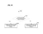
- FIG. 18 is a flow diagram of an example method 1800 for generating a data unit, according to an embodiment.
- the method 1800 is implemented by the network interface 16 , in an embodiment.
- the PHY processing unit 20 is configured to implement the method 1800 .
- the MAC processing 18 is also configured to implement at least a part of the method 1800 .
- the method 1800 is implemented by the network interface 27 (e.g., the PHY processing unit 29 and/or the MAC processing unit 28 ). In other embodiments, the method 1800 is implemented by other suitable network interfaces.
- the data unit is generated according to a first format. In an embodiment, the data unit 1200 of FIG. 12 is generated. In another embodiment, another suitable data unit is generated. On the other hand, if it is determined at block 1802 that the data unit is not to be transmitted in a regular mode (i.e., the data unit is to be transmitted in an extended range mode), then the data unit is generated according to a second format at block 1808 . In an embodiment, the data unit at block 1804 is generated using a FFT of size 64. In another embodiment, another suitable size FFT that is larger than 64 is utilized.
- the data unit at block 1804 is generated using a smaller size FFT, such as an FFT of size 32 or an FFT of size 16 or another suitable FFT size that is smaller than 64, and accordingly, the data unit generated at block 1808 has a bandwidth that is smaller compared to when the data unit is generated at block 1804 .
- a preamble of the data unit is modulated such that a receiving device can determine the bandwidth of the data unit.
- At least some of the various blocks, operations, and techniques described above may be implemented utilizing hardware, a processor executing firmware instructions, a processor executing software instructions, or any combination thereof. Also, some of the various blocks, operations, and techniques may be performed in a different order (and/or concurrently) and still achieve desirable results.
- the software or firmware instructions may be stored in any computer readable memory such as on a magnetic disk, an optical disk, or other storage medium, in a RAM or ROM or flash memory, processor, hard disk drive, optical disk drive, tape drive, etc.
- the software or firmware instructions may be delivered to a user or a system via any known or desired delivery method including, for example, on a computer readable disk or other transportable computer storage mechanism or via communication media.
- Communication media typically embodies computer readable instructions, data structures, program modules or other data in a modulated data signal such as a carrier wave or other transport mechanism.
- modulated data signal means a signal that has one or more of its characteristics set or changed in such a manner as to encode information in the signal.
- communication media includes wired media such as a wired network or direct-wired connection, and wireless media such as acoustic, radio frequency, infrared and other wireless media.
- the software or firmware instructions may be delivered to a user or a system via a communication channel such as a telephone line, a DSL line, a cable television line, a fiber optics line, a wireless communication channel, the Internet, etc. (which are viewed as being the same as or interchangeable with providing such software via a transportable storage medium).
- the software or firmware instructions may include machine readable instructions that, when executed by the processor, cause the processor to perform various acts.
- the hardware may comprise one or more of discrete components, an integrated circuit, an application-specific integrated circuit (ASIC), etc.
- ASIC application-specific integrated circuit
Abstract
Description
-
- U.S. Provisional Patent Application No. 61/437,506, entitled “Preamble of 11ah for WLAN Range Extension,” filed on Jan. 28, 2011;
- U.S. Provisional Patent Application No. 61/439,311, entitled “Preamble of 11ah for WLAN Range Extension,” filed on Feb. 3, 2011;
- U.S. Provisional Patent Application No. 61/440,788, entitled “Preamble of 11ah for WLAN Range Extension,” filed on Feb. 8, 2011;
- U.S. Provisional Patent Application No. 61/437,270, entitled “PHY Layer of 11ah for WLAN Range Extension,” filed on Jan. 28, 2011;
- U.S. Provisional Patent Application No. 61/439,773, entitled “PHY Layer of 11ah for WLAN Range Extension,” filed on Feb. 4, 2011; and
- U.S. Provisional Patent Application No. 61/440,797, entitled “PHY Layer of 11ah for WLAN Range Extension,” filed on Feb. 8, 2011;
where the subscript k denotes a tone index, Q is a spatial mapping matrix, DCSD is a diagonal matrix with diagonal elements representing cyclic shifts in the time domain, AHTLTF is a mapping matrix for the long training field, and LTFk is the long training field value for the kth tone. With continued reference to
[RHTLTF]m,n=[PHTLTF]m,1, 1≦m,n≦NHTLTF Equation 3
x k
where n is a symbol index. That is, in this case, the pilot tones in the data portion are also mapped to multiple spatial streams using the first column of the tone mapping matrix P.
[RHTLTF]m,n=[PHTLTF]1,m, 1≦m,n≦NHTLTF Equation 5
Accordingly, in this embodiment, all pilot tones in the HT-
where n is a symbol index. That is, in this case, the pilot tones in the data portion are also mapped to multiple spatial streams using the first row of the tone mapping matrix P.
Claims (18)
Priority Applications (3)
| Application Number | Priority Date | Filing Date | Title |
|---|---|---|---|
| US13/359,336 US8867653B2 (en) | 2011-01-28 | 2012-01-26 | Physical layer frame format for long range WLAN |
| US13/464,467 US8982889B2 (en) | 2008-07-18 | 2012-05-04 | Preamble designs for sub-1GHz frequency bands |
| US14/518,846 US9998950B2 (en) | 2011-01-28 | 2014-10-20 | Physical layer frame format for long range WLAN |
Applications Claiming Priority (7)
| Application Number | Priority Date | Filing Date | Title |
|---|---|---|---|
| US201161437270P | 2011-01-28 | 2011-01-28 | |
| US201161437506P | 2011-01-28 | 2011-01-28 | |
| US201161439311P | 2011-02-03 | 2011-02-03 | |
| US201161439773P | 2011-02-04 | 2011-02-04 | |
| US201161440797P | 2011-02-08 | 2011-02-08 | |
| US201161440788P | 2011-02-08 | 2011-02-08 | |
| US13/359,336 US8867653B2 (en) | 2011-01-28 | 2012-01-26 | Physical layer frame format for long range WLAN |
Related Child Applications (1)
| Application Number | Title | Priority Date | Filing Date |
|---|---|---|---|
| US14/518,846 Continuation US9998950B2 (en) | 2011-01-28 | 2014-10-20 | Physical layer frame format for long range WLAN |
Publications (2)
| Publication Number | Publication Date |
|---|---|
| US20120195391A1 US20120195391A1 (en) | 2012-08-02 |
| US8867653B2 true US8867653B2 (en) | 2014-10-21 |
Family
ID=45582050
Family Applications (2)
| Application Number | Title | Priority Date | Filing Date |
|---|---|---|---|
| US13/359,336 Active 2032-05-13 US8867653B2 (en) | 2008-07-18 | 2012-01-26 | Physical layer frame format for long range WLAN |
| US14/518,846 Active 2033-07-04 US9998950B2 (en) | 2011-01-28 | 2014-10-20 | Physical layer frame format for long range WLAN |
Family Applications After (1)
| Application Number | Title | Priority Date | Filing Date |
|---|---|---|---|
| US14/518,846 Active 2033-07-04 US9998950B2 (en) | 2011-01-28 | 2014-10-20 | Physical layer frame format for long range WLAN |
Country Status (6)
| Country | Link |
|---|---|
| US (2) | US8867653B2 (en) |
| EP (1) | EP2668736B1 (en) |
| JP (1) | JP5936280B2 (en) |
| KR (1) | KR101967412B1 (en) |
| CN (1) | CN103563283B (en) |
| WO (1) | WO2012103363A1 (en) |
Cited By (63)
| Publication number | Priority date | Publication date | Assignee | Title |
|---|---|---|---|---|
| US8982889B2 (en) | 2008-07-18 | 2015-03-17 | Marvell World Trade Ltd. | Preamble designs for sub-1GHz frequency bands |
| US9025540B2 (en) | 2011-02-08 | 2015-05-05 | Marvell World Trade Ltd. | WLAN channel allocation |
| US9031049B2 (en) | 2011-08-18 | 2015-05-12 | Marvell World Trade Ltd. | Signal field design for WLAN |
| US9077594B2 (en) | 2009-07-23 | 2015-07-07 | Marvell International Ltd. | Coexistence of a normal-rate physical layer and a low-rate physical layer in a wireless network |
| US9088991B2 (en) | 2011-11-02 | 2015-07-21 | Marvell World Trade Ltd | WLAN transmit modes and coexistence |
| US9119186B2 (en) | 2012-05-24 | 2015-08-25 | Marvell World Trade Ltd. | Frequency domain duplication in a long-range wireless local area network |
| US9124402B2 (en) | 2007-07-18 | 2015-09-01 | Marvell World Trade Ltd. | Method and apparatus for transmitting first data streams via respective transmitters to multiple clients stations during a same period and successively transmitting second data streams |
| US9130727B2 (en) | 2011-02-04 | 2015-09-08 | Marvell World Trade Ltd. | Control mode PHY for WLAN |
| US9130704B2 (en) | 2011-02-10 | 2015-09-08 | Marvell World Trade Ltd. | Multi-clock physical layer [[PHY] preamble design and detection |
| US9178745B2 (en) | 2011-02-04 | 2015-11-03 | Marvell World Trade Ltd. | Control mode PHY for WLAN |
| WO2015168634A1 (en) | 2014-05-01 | 2015-11-05 | Marvell World Trade Ltd. | Multi-clock phy preamble design and detection |
| US9226227B2 (en) | 2012-06-29 | 2015-12-29 | Marvell World Trade Ltd. | Group based beacons |
| US9226233B2 (en) | 2011-04-18 | 2015-12-29 | Marvell World Trade Ltd. | Reducing power consumption in a wireless communication system |
| US9246729B2 (en) | 2012-08-03 | 2016-01-26 | Marvell World Trade Ltd. | Multi-mode indication in subfield in a signal field of a wireless local area network data unit |
| US9294249B2 (en) | 2007-07-18 | 2016-03-22 | Marvell World Trade Ltd. | Method and apparatus for aggregating acknowledgments transmitted by an access point to a plurality of client stations in a wireless network |
| US9294326B2 (en) | 2011-10-27 | 2016-03-22 | Marvell World Trade Ltd. | Data unit format for multi-user data in long-range wireless local area networks (WLANS) |
| US20160112547A1 (en) * | 2012-04-26 | 2016-04-21 | Broadcom Corporation | Frame formatting for communications within single user, multiple user, multiple access, and/or MIMO wireless communications |
| US9350583B2 (en) | 2011-11-02 | 2016-05-24 | Marvell World Trade Ltd. | Method and apparatus for automatically detecting a physical layer (PHY) mode of a data unit in a wireless local area network (WLAN) |
| US9351333B1 (en) | 2011-11-30 | 2016-05-24 | Marvell International Ltd. | Long wireless local area network (WLAN) packets with midambles |
| US9398615B1 (en) | 2011-09-07 | 2016-07-19 | Marvell International Ltd. | Carrier sensing and symbol timing in a WLAN system |
| US9397873B2 (en) | 2014-06-11 | 2016-07-19 | Marvell World Trade Ltd. | Compressed orthogonal frequency division multiplexing (OFDM) symbols in a wireless communication system |
| US9414432B2 (en) | 2013-04-03 | 2016-08-09 | Marvell World Trade Ltd. | Physical layer frame format for WLAN |
| US9445349B1 (en) | 2012-04-18 | 2016-09-13 | Marvell International Ltd. | 802.11ah duty cycle based channel access priorities |
| US9584383B2 (en) | 2009-07-23 | 2017-02-28 | Marvell World Trade Ltd. | Coexistence of a normal-rate physical layer and a low-rate physical layer in a wireless network |
| US9591490B2 (en) | 2012-02-15 | 2017-03-07 | Marvell World Trade Ltd. | Low bandwidth PHY transmission in a wider bandwidth |
| US9596715B1 (en) | 2009-07-23 | 2017-03-14 | Marvell International Ltd. | Long wireless local area network (WLAN) packets with midambles |
| US9621322B2 (en) | 2011-05-26 | 2017-04-11 | Marvell World Trade Ltd. | NDP packet format for a communication protocol with multiple PHY modes |
| US9629127B2 (en) | 2014-05-02 | 2017-04-18 | Marvell World Trade Ltd. | Multiple user allocation signaling in a wireless communication network |
| US9647873B2 (en) | 2012-02-07 | 2017-05-09 | Marvell World Trade Ltd. | Pilot sequence design for long range WLAN |
| US9667460B2 (en) | 2013-10-25 | 2017-05-30 | Marvell World Trade Ltd. | Range extension mode for WiFi |
| US9674317B2 (en) | 2011-02-10 | 2017-06-06 | Marvell World Trade Ltd. | Multi-clock PHY preamble design and detection |
| US9706599B1 (en) | 2009-07-23 | 2017-07-11 | Marvell International Ltd. | Long wireless local area network (WLAN) packets with midambles |
| US9716607B2 (en) | 2010-07-01 | 2017-07-25 | Marvell World Trade Ltd. | Modulation of signal field in a WLAN frame header |
| US9729371B2 (en) | 2010-07-01 | 2017-08-08 | Marvell World Trade Ltd. | Orthogonal frequency division multiplexing (OFDM) symbol formats for a wireless local area network (WLAN) |
| US9736724B2 (en) | 2011-06-07 | 2017-08-15 | Marvell World Trade Ltd. | Physical layer frame format for long range WLAN |
| US9735855B2 (en) | 2012-04-18 | 2017-08-15 | Marvell World Trade Ltd. | Method and apparatus for relaying communication between an access point and a station in a wireless network |
| US9794044B2 (en) | 2014-09-23 | 2017-10-17 | Marvell World Trade Ltd. | Short training field for WiFi |
| US9826532B1 (en) | 2015-02-09 | 2017-11-21 | Marvell International Ltd. | Orthogonal frequency division multiple access resource request |
| US9918340B1 (en) | 2011-11-23 | 2018-03-13 | Marvell International Ltd. | Enhanced distributed channel access parameter variation within restricted access window |
| US9942193B1 (en) | 2014-12-05 | 2018-04-10 | Marvell International Ltd. | Basic service set color identifier |
| US9967772B1 (en) | 2013-07-25 | 2018-05-08 | Marvell International Ltd. | Systems and methods for suppressing interference in a wireless communication system |
| US9998950B2 (en) | 2011-01-28 | 2018-06-12 | Marvell World Trade Ltd. | Physical layer frame format for long range WLAN |
| US10033563B2 (en) | 2013-09-10 | 2018-07-24 | Marvell World Trade Ltd. | Extended guard interval for outdoor WLAN |
| US10038518B1 (en) | 2015-06-11 | 2018-07-31 | Marvell International Ltd. | Signaling phy preamble formats |
| US10080222B1 (en) | 2014-12-05 | 2018-09-18 | Marvell International Ltd. | Orthogonal frequency division multiple access short frame format |
| US10079918B2 (en) | 2015-02-17 | 2018-09-18 | Marvell World Trade Ltd. | Block coding scheme for PHY data unit transmission |
| US10079709B2 (en) | 2015-08-14 | 2018-09-18 | Marvell World Trade Ltd. | Physical layer data unit format for a wireless communication network |
| US10135572B2 (en) | 2012-04-03 | 2018-11-20 | Marvell World Trade Ltd. | Physical layer frame format for WLAN |
| US10181966B1 (en) | 2015-05-01 | 2019-01-15 | Marvell International Ltd. | WiFi classification by pilot sequences |
| US10194006B2 (en) | 2013-10-25 | 2019-01-29 | Marvell World Trade Ltd. | Physical layer frame format for WLAN |
| US10201009B1 (en) | 2015-08-13 | 2019-02-05 | Marvell International Ltd. | Methods and apparatus for protecting transmissions in a wireless communication network |
| US10218822B2 (en) | 2013-10-25 | 2019-02-26 | Marvell World Trade Ltd. | Physical layer frame format for WLAN |
| US10306603B1 (en) | 2015-02-09 | 2019-05-28 | Marvell International Ltd. | Resource request for uplink multi-user transmission |
| US10305659B2 (en) | 2016-04-12 | 2019-05-28 | Marvell World Trade Ltd. | Uplink multi-user transmission |
| US10382598B1 (en) | 2015-05-01 | 2019-08-13 | Marvell International Ltd. | Physical layer frame format for WLAN |
| US10492221B1 (en) | 2015-06-25 | 2019-11-26 | Marvell International Ltd. | Methods and apparatus for protecting transmissions in a wireless communication network |
| US10541796B2 (en) | 2017-06-09 | 2020-01-21 | Marvell World Trade Ltd. | Packets with midambles having compressed OFDM symbols |
| US10574418B2 (en) | 2016-04-14 | 2020-02-25 | Marvell World Trade Ltd. | Determining channel availability for orthogonal frequency division multiple access operation |
| US10715365B2 (en) | 2017-09-22 | 2020-07-14 | Nxp Usa, Inc. | Determining number of midambles in a packet |
| US10778392B2 (en) | 2018-04-26 | 2020-09-15 | Marvell Asia Pte, Ltd. | Pilots for wireless access in vehicular environments |
| US11032118B2 (en) | 2017-12-06 | 2021-06-08 | Marvell Asia Pte, Ltd. | Methods and apparatus for generation of physical layer protocol data units for vehicular environments |
| US11665036B2 (en) | 2019-04-09 | 2023-05-30 | Marvell Asia Pte Ltd | Generation and transmission of physical layer data units in a composite communication channel in a vehicular communication network |
| US11855818B1 (en) | 2014-04-30 | 2023-12-26 | Marvell Asia Pte Ltd | Adaptive orthogonal frequency division multiplexing (OFDM) numerology in a wireless communication network |
Families Citing this family (47)
| Publication number | Priority date | Publication date | Assignee | Title |
|---|---|---|---|---|
| US8737189B2 (en) * | 2005-02-16 | 2014-05-27 | Broadcom Corporation | Method and system for compromise greenfield preambles for 802.11n |
| US9674318B2 (en) * | 2010-12-09 | 2017-06-06 | Solarflare Communications, Inc. | TCP processing for devices |
| US9276795B2 (en) * | 2011-02-18 | 2016-03-01 | Qualcomm Incorporated | Data transmission coexistence within television white space channels |
| US8625690B2 (en) | 2011-03-04 | 2014-01-07 | Qualcomm Incorporated | Systems and methods for wireless communication in sub gigahertz bands |
| US9281928B2 (en) * | 2011-04-18 | 2016-03-08 | Broadcom Corporation | Range extension within single user, multiple user, multiple access, and/or MIMO wireless communications |
| US20130315323A1 (en) * | 2011-04-24 | 2013-11-28 | Broadcom Corporation | Traveling pilots within single user, multiple user, multiple access, and/or MIMO wireless communications |
| KR101538255B1 (en) * | 2011-04-26 | 2015-07-20 | 인텔 코포레이션 | Methods and arrangements for low power wireless networks |
| US8867675B1 (en) | 2011-08-04 | 2014-10-21 | Marvell International Ltd. | Low bandwidth PHY with frequency offset constraints |
| US9131399B2 (en) | 2011-08-15 | 2015-09-08 | Marvell World Trade Ltd. | Control data unit format for WLAN |
| JP6169581B2 (en) | 2011-10-19 | 2017-07-26 | マーベル ワールド トレード リミテッド | System and method for suppressing interference in a signal received by a device having two or more antennas |
| WO2013059566A1 (en) | 2011-10-20 | 2013-04-25 | Marvell World Trade Ltd. | Systems and methods for suppressing interference in a wireless communication system |
| US8953579B2 (en) | 2011-11-16 | 2015-02-10 | Marvell World Trade Ltd. | Frequency duplication mode for use in wireless local area networks (WLANs) |
| KR102015555B1 (en) | 2012-01-11 | 2019-08-28 | 마벨 월드 트레이드 리미티드 | Information bit padding schemes for wlan |
| EP2803175B1 (en) | 2012-01-13 | 2019-06-05 | Marvell World Trade Ltd. | Data unit format for single user beamforming in long-range wireless local area networks (wlans) |
| US8953720B1 (en) | 2012-01-20 | 2015-02-10 | Marvell International Ltd. | Packet type auto-detection in a wireless local area network (WLAN) |
| US9055468B2 (en) | 2012-04-02 | 2015-06-09 | Qualcomm Incorporated | Frame formats and timing parameters in sub-1 GHz networks |
| US9179496B2 (en) * | 2012-04-02 | 2015-11-03 | Qualcomm Incorporated | Tone scaling parameters in Sub-1 GHz networks |
| WO2014003898A1 (en) | 2012-05-15 | 2014-01-03 | Marvell World Trade Ltd. | Full and partial compressed feedback formats for wlan |
| US9386584B2 (en) | 2012-06-11 | 2016-07-05 | Qualcomm Incorporated | Inter-frame spacing duration for sub-1 gigahertz wireless networks |
| US20140044045A1 (en) * | 2012-08-10 | 2014-02-13 | Electronics And Telecommunications Research Institute | Structure of tvws ofdm phy frame |
| US9231809B2 (en) * | 2012-08-17 | 2016-01-05 | Intel Corporation | Methods and arrangements for phase tracking in wireless networks |
| US20140269666A1 (en) * | 2013-03-15 | 2014-09-18 | Qualcomm Incorporated | Method and apparatus for efficient signaling of communication mode and delimiter information |
| EP2996271B1 (en) | 2013-05-07 | 2019-09-11 | LG Electronics Inc. | Method and device for transmitting data unit |
| KR20150004497A (en) * | 2013-07-02 | 2015-01-13 | 한국전자통신연구원 | Apparatus and method for transmitting of tag and apparatus for receiving of reader |
| JP6219117B2 (en) * | 2013-10-09 | 2017-10-25 | 株式会社Nttドコモ | User terminal, radio base station, and radio communication method |
| US9668261B1 (en) | 2013-12-26 | 2017-05-30 | Marvell International Ltd. | Method and apparatus for transmitting wireless network operational information |
| JP6208016B2 (en) * | 2014-01-06 | 2017-10-04 | パナソニック株式会社 | Wireless communication apparatus and wireless communication method |
| US10194388B2 (en) * | 2014-03-31 | 2019-01-29 | Samsung Electronics Co., Ltd. | Method and apparatus to enable low power synchronization for large bandwidth wireless LAN systems |
| JPWO2015162886A1 (en) * | 2014-04-24 | 2017-04-13 | パナソニック インテレクチュアル プロパティ コーポレーション オブ アメリカPanasonic Intellectual Property Corporation of America | Transmitter |
| WO2015198158A2 (en) * | 2014-06-27 | 2015-12-30 | Techflux, Ltd. | Operating in power save mode |
| CN104202288B (en) * | 2014-08-27 | 2015-06-03 | 江苏中兴微通信息科技有限公司 | Data receiving and sending method and device of mixed carrier modulation MIMO system |
| US10154476B2 (en) * | 2014-09-04 | 2018-12-11 | Qualcomm Incorporated | Tone plan for LTF compression |
| US9893784B2 (en) * | 2014-10-28 | 2018-02-13 | Newracom, Inc. | LTF design for WLAN system |
| EP3955506B1 (en) * | 2014-10-31 | 2023-05-10 | LG Electronics Inc. | Multiuser transreceiving method in wireless communication system and device for same |
| US9674011B1 (en) | 2015-02-10 | 2017-06-06 | Marvel International Ltd. | Auto-detection of repeated signals |
| US10285149B2 (en) | 2015-06-15 | 2019-05-07 | Qualcomm Incorporated | Orthogonal training field sequences for phase tracking |
| US9948546B2 (en) * | 2015-08-28 | 2018-04-17 | Apple Inc. | Efficient auto detection for next generation WLAN |
| US10103792B2 (en) * | 2016-01-14 | 2018-10-16 | Intel Corporation | Apparatus, system and method of communicating a multiple-input-multiple-output (MIMO) transmission |
| US10924218B2 (en) | 2016-07-20 | 2021-02-16 | Intel IP Corporation | Apparatus, system and method of communicating a single carrier (SC) transmission |
| US10979266B2 (en) * | 2016-11-07 | 2021-04-13 | Wilus Institute Of Standards And Technology Inc. | Method for wireless communication with wireless communication terminal for long distance transmission and wireless communication terminal using same |
| TWI641240B (en) * | 2017-04-07 | 2018-11-11 | 濎通科技股份有限公司 | Power line communication device and method |
| CN107426805B (en) * | 2017-07-13 | 2020-01-31 | 北京千丁互联科技有限公司 | Wireless node device, data transmitting apparatus, data transmitting method, and data receiving method |
| CN111165058B (en) * | 2017-10-02 | 2023-10-31 | 索尼公司 | Radio communication apparatus, method and program thereof |
| US10785682B2 (en) * | 2017-12-06 | 2020-09-22 | Mediatek Inc. | Data unit processing method and communication device applying the data unit processing method |
| CN111181885B (en) * | 2018-11-13 | 2022-09-09 | 中国科学院上海高等研究院 | Method for transmitting and receiving preamble signal in ultra-high speed mobile broadband communication |
| US11398886B2 (en) * | 2019-07-12 | 2022-07-26 | Newracom, Inc. | Midamble operation in a wireless local area network |
| US11606185B2 (en) * | 2019-11-12 | 2023-03-14 | Marvell Asia Pte Ltd | Detection of physical layer parameter of a master device in an ethernet network |
Citations (19)
| Publication number | Priority date | Publication date | Assignee | Title |
|---|---|---|---|---|
| WO2003005652A1 (en) | 2001-07-06 | 2003-01-16 | Intersil Americas Inc. | Wireless communication system configured to communicate using a mixed waveform configuration |
| US20080298435A1 (en) | 2006-11-30 | 2008-12-04 | Ismail Lakkis | Common Air Interface Supporting Single Carrier and OFDM |
| US20080299962A1 (en) | 2007-05-30 | 2008-12-04 | Assaf Kasher | Providing extended range modes as part of the 802.11n standard |
| WO2009059229A1 (en) | 2007-10-31 | 2009-05-07 | Qualcomm Incorporated | Method and apparatus for signaling transmission characteristics in a wireless communication network |
| US20090196163A1 (en) | 2006-07-05 | 2009-08-06 | Koninklijke Philips Electronics N.V. | Bandwidth asymmetric communication system based on ofdm and tdma |
| WO2009114612A1 (en) | 2008-03-11 | 2009-09-17 | Broadcom Corporation | Method and system for dual mode operation in wireless networks |
| US20090285319A1 (en) | 2008-05-15 | 2009-11-19 | Hongyuan Zhang | Efficient Physical Layer Preamble Format |
| US20100046656A1 (en) | 2008-08-20 | 2010-02-25 | Qualcomm Incorporated | Preamble extensions |
| US20110134899A1 (en) * | 2009-12-07 | 2011-06-09 | Qualcomm Incorporated | Enabling phase tracking for a communication device |
| US20110142020A1 (en) * | 2009-12-10 | 2011-06-16 | Lg Electronics Inc. | Method and apparatus of transmitting training signal in wireless local area network system |
| US20110299382A1 (en) * | 2010-06-07 | 2011-12-08 | Qualcomm Incorporated | Communication devices for generating and using a matrix-mapped sequence |
| US20110305296A1 (en) * | 2010-06-15 | 2011-12-15 | Qualcomm Incorporated | Using a field format on a communication device |
| US20120039406A1 (en) * | 2010-08-10 | 2012-02-16 | Sudhir Srinivasa | Channel description feedback in a communication system |
| WO2012122119A1 (en) | 2011-03-04 | 2012-09-13 | Qualcomm Incorporated | Systems and methods for wireless communication in sub gigahertz bands |
| US20120300874A1 (en) * | 2011-05-26 | 2012-11-29 | Hongyuan Zhang | Sounding packet format for long range wlan |
| US8462863B1 (en) | 2009-07-23 | 2013-06-11 | Marvell International Ltd. | Midamble for WLAN PHY frames |
| US8498362B2 (en) | 2008-02-01 | 2013-07-30 | Marvell World Trade Ltd. | Channel sounding and estimation strategies for antenna selection in MIMO systems |
| US8527853B2 (en) | 2005-11-16 | 2013-09-03 | Qualcomm Incorporated | Golay-code generation |
| US8542589B2 (en) | 2006-06-05 | 2013-09-24 | Qualcomm Incorporated | Method and apparatus for providing beamforming feedback in wireless communication systems |
Family Cites Families (25)
| Publication number | Priority date | Publication date | Assignee | Title |
|---|---|---|---|---|
| US7161987B2 (en) * | 2001-09-26 | 2007-01-09 | Conexant, Inc. | Single-carrier to multi-carrier wireless architecture |
| DE10331818B3 (en) * | 2003-07-14 | 2005-03-10 | Infineon Technologies Ag | Method for estimating the DC offset of an OFDM received signal, apparatus for carrying out the method, radio receiver with such a device, and method for compensating for a DC offset of an OFDM received signal, apparatus for carrying out this method and radio receiver with such a device |
| US7539260B2 (en) | 2004-05-27 | 2009-05-26 | Qualcomm Incorporated | Detecting the number of transmit antennas in wireless communication systems |
| US8619907B2 (en) | 2004-06-10 | 2013-12-31 | Agere Systems, LLC | Method and apparatus for preamble training in a multiple antenna communication system |
| KR100643299B1 (en) * | 2005-06-09 | 2006-11-10 | 삼성전자주식회사 | Method and apparatus for transmitting and receiving legacy format data in high throughput wireless network |
| US7742390B2 (en) | 2005-08-23 | 2010-06-22 | Agere Systems Inc. | Method and apparatus for improved long preamble formats in a multiple antenna communication system |
| US8724676B2 (en) * | 2005-11-16 | 2014-05-13 | Qualcomm Incorporated | Method and apparatus for single carrier spreading |
| JP4816123B2 (en) * | 2006-02-17 | 2011-11-16 | ソニー株式会社 | Wireless communication apparatus and wireless communication method |
| US7983356B2 (en) * | 2007-06-29 | 2011-07-19 | Qualcomm, Incorporated | Enhanced frequency domain spreading |
| US20090092039A1 (en) * | 2007-10-03 | 2009-04-09 | Samsung Electronics Co., Ltd. | Method and system for formation and communication of information frames in wireless communication systems |
| EP2277270B1 (en) * | 2008-05-15 | 2014-06-11 | Marvell World Trade Ltd. | Phy preamble format for wireless communication system |
| CN101325575B (en) * | 2008-05-28 | 2011-05-25 | 苏州中科半导体集成技术研发中心有限公司 | Method for implementing frame synchronization of OFDM system |
| JP5315546B2 (en) * | 2008-07-08 | 2013-10-16 | マーベル ワールド トレード リミテッド | Methods and systems |
| US8867653B2 (en) | 2011-01-28 | 2014-10-21 | Marvell World Trade Ltd. | Physical layer frame format for long range WLAN |
| US8155138B2 (en) | 2008-08-19 | 2012-04-10 | Qualcomm Incorporated | Training sequences for very high throughput wireless communication |
| JP2010093704A (en) | 2008-10-10 | 2010-04-22 | Sony Corp | Radio communication system, radio communication device and radio communication method, and computer program |
| JP4631956B2 (en) | 2008-10-14 | 2011-02-16 | ソニー株式会社 | Wireless communication apparatus and wireless communication method |
| US9084119B2 (en) * | 2009-01-07 | 2015-07-14 | Qualcomm Incorporated | Carrier reuse in a multicarrier wireless communication environment |
| KR101646721B1 (en) * | 2009-04-13 | 2016-08-12 | 마벨 월드 트레이드 리미티드 | Physical layer frame format for wlan |
| US9197298B2 (en) | 2009-06-05 | 2015-11-24 | Broadcom Corporation | Group identification and definition within multiple user, multiple access, and/or MIMO wireless communications |
| US8526351B2 (en) | 2009-06-05 | 2013-09-03 | Broadcom Corporation | Channel characterization and training within multiple user, multiple access, and/or MIMO wireless communications |
| US8724720B2 (en) | 2009-07-29 | 2014-05-13 | Marvell World Trade Ltd. | Methods and apparatus for WLAN transmission |
| US8599804B2 (en) | 2009-08-07 | 2013-12-03 | Broadcom Corporation | Distributed signal field for communications within multiple user, multiple access, and/or MIMO wireless communications |
| GB2473674A (en) * | 2009-09-22 | 2011-03-23 | Sony Corp | OFDM receiver with a plurality of prediction filters to reduce noise in channel transfer function estimates |
| CN101778066B (en) * | 2009-12-31 | 2013-01-23 | 北京交通大学 | Physical layer preamble optimization-based synchronization method and system |
-
2012
- 2012-01-26 US US13/359,336 patent/US8867653B2/en active Active
- 2012-01-26 EP EP12703655.6A patent/EP2668736B1/en active Active
- 2012-01-26 JP JP2013551344A patent/JP5936280B2/en active Active
- 2012-01-26 KR KR1020137022099A patent/KR101967412B1/en active IP Right Grant
- 2012-01-26 WO PCT/US2012/022768 patent/WO2012103363A1/en active Application Filing
- 2012-01-26 CN CN201280014281.5A patent/CN103563283B/en active Active
-
2014
- 2014-10-20 US US14/518,846 patent/US9998950B2/en active Active
Patent Citations (20)
| Publication number | Priority date | Publication date | Assignee | Title |
|---|---|---|---|---|
| WO2003005652A1 (en) | 2001-07-06 | 2003-01-16 | Intersil Americas Inc. | Wireless communication system configured to communicate using a mixed waveform configuration |
| US8527853B2 (en) | 2005-11-16 | 2013-09-03 | Qualcomm Incorporated | Golay-code generation |
| US8542589B2 (en) | 2006-06-05 | 2013-09-24 | Qualcomm Incorporated | Method and apparatus for providing beamforming feedback in wireless communication systems |
| US20090196163A1 (en) | 2006-07-05 | 2009-08-06 | Koninklijke Philips Electronics N.V. | Bandwidth asymmetric communication system based on ofdm and tdma |
| US20080298435A1 (en) | 2006-11-30 | 2008-12-04 | Ismail Lakkis | Common Air Interface Supporting Single Carrier and OFDM |
| US20080299962A1 (en) | 2007-05-30 | 2008-12-04 | Assaf Kasher | Providing extended range modes as part of the 802.11n standard |
| WO2009059229A1 (en) | 2007-10-31 | 2009-05-07 | Qualcomm Incorporated | Method and apparatus for signaling transmission characteristics in a wireless communication network |
| US8498362B2 (en) | 2008-02-01 | 2013-07-30 | Marvell World Trade Ltd. | Channel sounding and estimation strategies for antenna selection in MIMO systems |
| WO2009114612A1 (en) | 2008-03-11 | 2009-09-17 | Broadcom Corporation | Method and system for dual mode operation in wireless networks |
| US8331419B2 (en) | 2008-05-15 | 2012-12-11 | Marvell World Trade Ltd. | Efficient physical layer preamble format |
| US20090285319A1 (en) | 2008-05-15 | 2009-11-19 | Hongyuan Zhang | Efficient Physical Layer Preamble Format |
| US20100046656A1 (en) | 2008-08-20 | 2010-02-25 | Qualcomm Incorporated | Preamble extensions |
| US8462863B1 (en) | 2009-07-23 | 2013-06-11 | Marvell International Ltd. | Midamble for WLAN PHY frames |
| US20110134899A1 (en) * | 2009-12-07 | 2011-06-09 | Qualcomm Incorporated | Enabling phase tracking for a communication device |
| US20110142020A1 (en) * | 2009-12-10 | 2011-06-16 | Lg Electronics Inc. | Method and apparatus of transmitting training signal in wireless local area network system |
| US20110299382A1 (en) * | 2010-06-07 | 2011-12-08 | Qualcomm Incorporated | Communication devices for generating and using a matrix-mapped sequence |
| US20110305296A1 (en) * | 2010-06-15 | 2011-12-15 | Qualcomm Incorporated | Using a field format on a communication device |
| US20120039406A1 (en) * | 2010-08-10 | 2012-02-16 | Sudhir Srinivasa | Channel description feedback in a communication system |
| WO2012122119A1 (en) | 2011-03-04 | 2012-09-13 | Qualcomm Incorporated | Systems and methods for wireless communication in sub gigahertz bands |
| US20120300874A1 (en) * | 2011-05-26 | 2012-11-29 | Hongyuan Zhang | Sounding packet format for long range wlan |
Non-Patent Citations (45)
Cited By (115)
| Publication number | Priority date | Publication date | Assignee | Title |
|---|---|---|---|---|
| US9294249B2 (en) | 2007-07-18 | 2016-03-22 | Marvell World Trade Ltd. | Method and apparatus for aggregating acknowledgments transmitted by an access point to a plurality of client stations in a wireless network |
| US9480064B2 (en) | 2007-07-18 | 2016-10-25 | Marvell World Trade Ltd. | Method and apparatus for transmitting first data streams via respective transmitters to multiple client stations during a same period and successively transmitting second data streams |
| US9628246B2 (en) | 2007-07-18 | 2017-04-18 | Marvell World Trade Ltd. | Aggregating acknowledgments transmitted by an access point to a plurality of client stations in a wireless network |
| US9124402B2 (en) | 2007-07-18 | 2015-09-01 | Marvell World Trade Ltd. | Method and apparatus for transmitting first data streams via respective transmitters to multiple clients stations during a same period and successively transmitting second data streams |
| US8982889B2 (en) | 2008-07-18 | 2015-03-17 | Marvell World Trade Ltd. | Preamble designs for sub-1GHz frequency bands |
| US9860823B2 (en) | 2009-07-23 | 2018-01-02 | Marvell International Ltd. | Method and apparatus for reducing interference between wireless devices operating at different data rates in a wireless network |
| US9088466B2 (en) | 2009-07-23 | 2015-07-21 | Marvell World Trade Ltd. | Coexistence of a normal-rate physical layer and a low-rate physical layer in a wireless network |
| US9077594B2 (en) | 2009-07-23 | 2015-07-07 | Marvell International Ltd. | Coexistence of a normal-rate physical layer and a low-rate physical layer in a wireless network |
| US9584383B2 (en) | 2009-07-23 | 2017-02-28 | Marvell World Trade Ltd. | Coexistence of a normal-rate physical layer and a low-rate physical layer in a wireless network |
| US10070482B1 (en) | 2009-07-23 | 2018-09-04 | Marvell International Ltd. | Midamble for WLAN PHY frames |
| US9706599B1 (en) | 2009-07-23 | 2017-07-11 | Marvell International Ltd. | Long wireless local area network (WLAN) packets with midambles |
| US11006480B1 (en) | 2009-07-23 | 2021-05-11 | Marvell Asia Pte, Ltd. | Midamble for WLAN PHY packets |
| US10368391B1 (en) | 2009-07-23 | 2019-07-30 | Marvell International Ltd. | Midamble for WLAN PHY packets |
| US9596715B1 (en) | 2009-07-23 | 2017-03-14 | Marvell International Ltd. | Long wireless local area network (WLAN) packets with midambles |
| US9713065B2 (en) | 2009-07-23 | 2017-07-18 | Marvell World Trade Ltd. | Coexistence of devices operating at different data rates in wireless networks |
| US9729371B2 (en) | 2010-07-01 | 2017-08-08 | Marvell World Trade Ltd. | Orthogonal frequency division multiplexing (OFDM) symbol formats for a wireless local area network (WLAN) |
| US9716607B2 (en) | 2010-07-01 | 2017-07-25 | Marvell World Trade Ltd. | Modulation of signal field in a WLAN frame header |
| US9998950B2 (en) | 2011-01-28 | 2018-06-12 | Marvell World Trade Ltd. | Physical layer frame format for long range WLAN |
| US10397033B2 (en) | 2011-02-04 | 2019-08-27 | Marvell World Trade Ltd. | Method and apparatus for generating a PHY data unit |
| US9178745B2 (en) | 2011-02-04 | 2015-11-03 | Marvell World Trade Ltd. | Control mode PHY for WLAN |
| US9130727B2 (en) | 2011-02-04 | 2015-09-08 | Marvell World Trade Ltd. | Control mode PHY for WLAN |
| US9419849B2 (en) | 2011-02-04 | 2016-08-16 | Marvell World Trade Ltd. | Method and apparatus for generating a PHY data unit |
| US9025540B2 (en) | 2011-02-08 | 2015-05-05 | Marvell World Trade Ltd. | WLAN channel allocation |
| US9674317B2 (en) | 2011-02-10 | 2017-06-06 | Marvell World Trade Ltd. | Multi-clock PHY preamble design and detection |
| US9130704B2 (en) | 2011-02-10 | 2015-09-08 | Marvell World Trade Ltd. | Multi-clock physical layer [[PHY] preamble design and detection |
| US9226233B2 (en) | 2011-04-18 | 2015-12-29 | Marvell World Trade Ltd. | Reducing power consumption in a wireless communication system |
| US10536899B2 (en) | 2011-04-18 | 2020-01-14 | Marvell World Trade Ltd. | Prioritizing sensor data and cellular offload data in a wireless network |
| US9374782B2 (en) | 2011-04-18 | 2016-06-21 | Marvell World Trade Ltd. | Reducing power consumption in a wireless communication system |
| US9706546B2 (en) | 2011-05-16 | 2017-07-11 | Marvell World Trade Ltd. | Preambles for sub-1GHz frequency bands |
| US10178665B2 (en) | 2011-05-16 | 2019-01-08 | Marvell World Trade Ltd | Systems and methods for transmitting packets in sub-1GHz frequency bands |
| US9621322B2 (en) | 2011-05-26 | 2017-04-11 | Marvell World Trade Ltd. | NDP packet format for a communication protocol with multiple PHY modes |
| US10064094B2 (en) | 2011-05-26 | 2018-08-28 | Marvell World Trade Ltd. | Null data packet format for long range WLAN |
| US9736724B2 (en) | 2011-06-07 | 2017-08-15 | Marvell World Trade Ltd. | Physical layer frame format for long range WLAN |
| US9031049B2 (en) | 2011-08-18 | 2015-05-12 | Marvell World Trade Ltd. | Signal field design for WLAN |
| US9398615B1 (en) | 2011-09-07 | 2016-07-19 | Marvell International Ltd. | Carrier sensing and symbol timing in a WLAN system |
| US9294326B2 (en) | 2011-10-27 | 2016-03-22 | Marvell World Trade Ltd. | Data unit format for multi-user data in long-range wireless local area networks (WLANS) |
| US9088991B2 (en) | 2011-11-02 | 2015-07-21 | Marvell World Trade Ltd | WLAN transmit modes and coexistence |
| US9350583B2 (en) | 2011-11-02 | 2016-05-24 | Marvell World Trade Ltd. | Method and apparatus for automatically detecting a physical layer (PHY) mode of a data unit in a wireless local area network (WLAN) |
| US9918340B1 (en) | 2011-11-23 | 2018-03-13 | Marvell International Ltd. | Enhanced distributed channel access parameter variation within restricted access window |
| US9351333B1 (en) | 2011-11-30 | 2016-05-24 | Marvell International Ltd. | Long wireless local area network (WLAN) packets with midambles |
| US9647873B2 (en) | 2012-02-07 | 2017-05-09 | Marvell World Trade Ltd. | Pilot sequence design for long range WLAN |
| US9591490B2 (en) | 2012-02-15 | 2017-03-07 | Marvell World Trade Ltd. | Low bandwidth PHY transmission in a wider bandwidth |
| US10135572B2 (en) | 2012-04-03 | 2018-11-20 | Marvell World Trade Ltd. | Physical layer frame format for WLAN |
| US10742357B2 (en) | 2012-04-03 | 2020-08-11 | Marvell International Ltd. | Physical layer frame format for WLAN |
| US9445349B1 (en) | 2012-04-18 | 2016-09-13 | Marvell International Ltd. | 802.11ah duty cycle based channel access priorities |
| US9735855B2 (en) | 2012-04-18 | 2017-08-15 | Marvell World Trade Ltd. | Method and apparatus for relaying communication between an access point and a station in a wireless network |
| US10547714B2 (en) | 2012-04-26 | 2020-01-28 | Avago Technologies International Sales Pte. Limited | Frame formatting for communications within single user, multiple user, multiple access, and/or MIMO wireless communications |
| US20160112547A1 (en) * | 2012-04-26 | 2016-04-21 | Broadcom Corporation | Frame formatting for communications within single user, multiple user, multiple access, and/or MIMO wireless communications |
| US20180176343A1 (en) * | 2012-04-26 | 2018-06-21 | Avago Technologies General Ip (Singapore) Pte. Ltd. | Frame formatting for communications within single user, multiple user, multiple access, and/or MIMO wireless communications |
| US11641412B2 (en) | 2012-04-26 | 2023-05-02 | Avago Technologies International Sales Pte. Limited | Frame formatting for communications within single user, multiple user, multiple access, and/or MIMO wireless communications |
| US9923999B2 (en) * | 2012-04-26 | 2018-03-20 | Avago Technologies General Ip (Singapore) Pte. Ltd. | Frame formatting for communications within single user, multiple user, multiple access, and/or MIMO wireless communications |
| US9432154B2 (en) | 2012-05-24 | 2016-08-30 | Marvell World Trade Ltd. | Frequency domain duplication in a long-range wireless local area network |
| US9119186B2 (en) | 2012-05-24 | 2015-08-25 | Marvell World Trade Ltd. | Frequency domain duplication in a long-range wireless local area network |
| US9226227B2 (en) | 2012-06-29 | 2015-12-29 | Marvell World Trade Ltd. | Group based beacons |
| US9386516B2 (en) | 2012-06-29 | 2016-07-05 | Marvell World Trade Ltd. | Using duration field in beacon to reserve channel time subsequent to beacon |
| US9596648B2 (en) | 2012-06-29 | 2017-03-14 | Marvell World Trade Ltd. | Unified beacon format |
| US9246729B2 (en) | 2012-08-03 | 2016-01-26 | Marvell World Trade Ltd. | Multi-mode indication in subfield in a signal field of a wireless local area network data unit |
| US9775097B1 (en) | 2012-08-15 | 2017-09-26 | Marvell International Ltd. | Systems and methods for requesting duty cycle based channel access priorities |
| US9414432B2 (en) | 2013-04-03 | 2016-08-09 | Marvell World Trade Ltd. | Physical layer frame format for WLAN |
| US10212759B2 (en) | 2013-05-10 | 2019-02-19 | Marvell World Trade Ltd. | Physical layer frame format for WLAN |
| US9967772B1 (en) | 2013-07-25 | 2018-05-08 | Marvell International Ltd. | Systems and methods for suppressing interference in a wireless communication system |
| US10033563B2 (en) | 2013-09-10 | 2018-07-24 | Marvell World Trade Ltd. | Extended guard interval for outdoor WLAN |
| US11671296B2 (en) | 2013-09-10 | 2023-06-06 | Marvell Asia Pte Ltd | Extended guard interval for outdoor WLAN |
| US10291752B2 (en) | 2013-10-25 | 2019-05-14 | Marvell World Trade Ltd. | Physical layer frame format for WLAN |
| US11962444B2 (en) | 2013-10-25 | 2024-04-16 | Marvell Asia Pte Ltd | Physical layer frame format for WLAN |
| US10389562B2 (en) | 2013-10-25 | 2019-08-20 | Marvell World Trade Ltd. | Range extension mode for WiFi |
| US10153930B2 (en) | 2013-10-25 | 2018-12-11 | Marvell World Trade Ltd. | Range extension mode for WiFi |
| US11165892B2 (en) | 2013-10-25 | 2021-11-02 | Marvell Asia Pte, Ltd. | Physical layer frame format for WLAN |
| US11146434B2 (en) | 2013-10-25 | 2021-10-12 | Marvell Asia Pte, Ltd. | Range extension mode for WiFi |
| US10194006B2 (en) | 2013-10-25 | 2019-01-29 | Marvell World Trade Ltd. | Physical layer frame format for WLAN |
| US9712358B2 (en) | 2013-10-25 | 2017-07-18 | Marvell World Trade Ltd. | Range extension mode for WiFi |
| US9667460B2 (en) | 2013-10-25 | 2017-05-30 | Marvell World Trade Ltd. | Range extension mode for WiFi |
| US10218822B2 (en) | 2013-10-25 | 2019-02-26 | Marvell World Trade Ltd. | Physical layer frame format for WLAN |
| US11855818B1 (en) | 2014-04-30 | 2023-12-26 | Marvell Asia Pte Ltd | Adaptive orthogonal frequency division multiplexing (OFDM) numerology in a wireless communication network |
| WO2015168634A1 (en) | 2014-05-01 | 2015-11-05 | Marvell World Trade Ltd. | Multi-clock phy preamble design and detection |
| US9629127B2 (en) | 2014-05-02 | 2017-04-18 | Marvell World Trade Ltd. | Multiple user allocation signaling in a wireless communication network |
| US9954703B2 (en) | 2014-06-11 | 2018-04-24 | Marvell World Trade Ltd. | Compressed preamble for a wireless communication system |
| US10904058B2 (en) | 2014-06-11 | 2021-01-26 | Nxp Usa, Inc. | Padding for orthogonal frequency division multiplexing (OFDM) symbols in a wireless communication system |
| US9768996B2 (en) | 2014-06-11 | 2017-09-19 | Marvell World Trade Ltd. | Compressed orthogonal frequency division multiplexing (OFDM) symbols in a wireless communication system |
| US10958492B2 (en) | 2014-06-11 | 2021-03-23 | Nxp Usa, Inc. | Compressed preamble for a wireless communication system |
| US9397873B2 (en) | 2014-06-11 | 2016-07-19 | Marvell World Trade Ltd. | Compressed orthogonal frequency division multiplexing (OFDM) symbols in a wireless communication system |
| US10469297B2 (en) | 2014-06-11 | 2019-11-05 | Marvell World Trade Ltd. | Padding for orthogonal frequency division multiplexing (OFDM) symbols in a wireless communication system |
| US10116477B2 (en) | 2014-06-11 | 2018-10-30 | Marvell World Trade Ltd. | Padding for orthogonal frequency division multiplexing (OFDM) symbols in a wireless communication system |
| US10979198B2 (en) | 2014-09-23 | 2021-04-13 | Nxp Usa, Inc. | Short training field for WiFi |
| US10419187B2 (en) | 2014-09-23 | 2019-09-17 | Marvell World Trade Ltd. | Short training field for WiFi |
| US10454648B2 (en) | 2014-09-23 | 2019-10-22 | Marvell World Trade Ltd. | Short training field for WiFi |
| US10038540B2 (en) | 2014-09-23 | 2018-07-31 | Marvell World Trade Ltd. | Short training field for WiFi |
| US9794044B2 (en) | 2014-09-23 | 2017-10-17 | Marvell World Trade Ltd. | Short training field for WiFi |
| US10080222B1 (en) | 2014-12-05 | 2018-09-18 | Marvell International Ltd. | Orthogonal frequency division multiple access short frame format |
| US9942193B1 (en) | 2014-12-05 | 2018-04-10 | Marvell International Ltd. | Basic service set color identifier |
| US10404653B1 (en) | 2014-12-05 | 2019-09-03 | Marvell International Ltd. | Changing a basic service set color identifier |
| US11032237B1 (en) | 2014-12-05 | 2021-06-08 | Nxp Usa, Inc. | Changing a basic service set color identifier |
| US10306603B1 (en) | 2015-02-09 | 2019-05-28 | Marvell International Ltd. | Resource request for uplink multi-user transmission |
| US10708892B1 (en) | 2015-02-09 | 2020-07-07 | Nxp Usa, Inc. | Resource request for uplink transmission |
| US9826532B1 (en) | 2015-02-09 | 2017-11-21 | Marvell International Ltd. | Orthogonal frequency division multiple access resource request |
| US10079918B2 (en) | 2015-02-17 | 2018-09-18 | Marvell World Trade Ltd. | Block coding scheme for PHY data unit transmission |
| US10181966B1 (en) | 2015-05-01 | 2019-01-15 | Marvell International Ltd. | WiFi classification by pilot sequences |
| US10382598B1 (en) | 2015-05-01 | 2019-08-13 | Marvell International Ltd. | Physical layer frame format for WLAN |
| US10348446B1 (en) | 2015-06-11 | 2019-07-09 | Marvell International Ltd. | Signaling PHY preamble formats |
| US10797821B1 (en) | 2015-06-11 | 2020-10-06 | Nxp Usa, Inc. | Signaling PHY preamble formats |
| US10038518B1 (en) | 2015-06-11 | 2018-07-31 | Marvell International Ltd. | Signaling phy preamble formats |
| US10492221B1 (en) | 2015-06-25 | 2019-11-26 | Marvell International Ltd. | Methods and apparatus for protecting transmissions in a wireless communication network |
| US11297646B1 (en) | 2015-06-25 | 2022-04-05 | Nxp Usa, Inc. | Methods and apparatus for protecting transmissions in a wireless communication network |
| US10201009B1 (en) | 2015-08-13 | 2019-02-05 | Marvell International Ltd. | Methods and apparatus for protecting transmissions in a wireless communication network |
| US10079709B2 (en) | 2015-08-14 | 2018-09-18 | Marvell World Trade Ltd. | Physical layer data unit format for a wireless communication network |
| US10305659B2 (en) | 2016-04-12 | 2019-05-28 | Marvell World Trade Ltd. | Uplink multi-user transmission |
| US10931421B2 (en) | 2016-04-12 | 2021-02-23 | Nxp Usa, Inc. | Communicating subchannel availability information in a wireless local area network |
| US10574418B2 (en) | 2016-04-14 | 2020-02-25 | Marvell World Trade Ltd. | Determining channel availability for orthogonal frequency division multiple access operation |
| US10541796B2 (en) | 2017-06-09 | 2020-01-21 | Marvell World Trade Ltd. | Packets with midambles having compressed OFDM symbols |
| US10715365B2 (en) | 2017-09-22 | 2020-07-14 | Nxp Usa, Inc. | Determining number of midambles in a packet |
| US11032118B2 (en) | 2017-12-06 | 2021-06-08 | Marvell Asia Pte, Ltd. | Methods and apparatus for generation of physical layer protocol data units for vehicular environments |
| US11558226B2 (en) | 2017-12-06 | 2023-01-17 | Marvell Asia Pte Ltd | Methods and apparatus for generation of physical layer protocol data units for vehicular environments |
| US11870625B2 (en) | 2017-12-06 | 2024-01-09 | Marvell Asia Pte Ltd | Methods and apparatus for generation of physical layer protocol data units for vehicular environments |
| US10778392B2 (en) | 2018-04-26 | 2020-09-15 | Marvell Asia Pte, Ltd. | Pilots for wireless access in vehicular environments |
| US11665036B2 (en) | 2019-04-09 | 2023-05-30 | Marvell Asia Pte Ltd | Generation and transmission of physical layer data units in a composite communication channel in a vehicular communication network |
Also Published As
| Publication number | Publication date |
|---|---|
| KR20140018248A (en) | 2014-02-12 |
| EP2668736B1 (en) | 2018-04-25 |
| CN103563283A (en) | 2014-02-05 |
| US20120195391A1 (en) | 2012-08-02 |
| KR101967412B1 (en) | 2019-04-10 |
| JP5936280B2 (en) | 2016-06-22 |
| US9998950B2 (en) | 2018-06-12 |
| JP2014505436A (en) | 2014-02-27 |
| US20150350950A1 (en) | 2015-12-03 |
| WO2012103363A1 (en) | 2012-08-02 |
| EP2668736A1 (en) | 2013-12-04 |
| CN103563283B (en) | 2016-08-31 |
Similar Documents
| Publication | Publication Date | Title |
|---|---|---|
| US9998950B2 (en) | Physical layer frame format for long range WLAN | |
| US10064094B2 (en) | Null data packet format for long range WLAN | |
| US9674317B2 (en) | Multi-clock PHY preamble design and detection | |
| US8644128B2 (en) | Multi-clock PHY preamble design and detection | |
| US10397033B2 (en) | Method and apparatus for generating a PHY data unit | |
| US9419849B2 (en) | Method and apparatus for generating a PHY data unit | |
| US8989392B2 (en) | Physical layer frame format for long range WLAN | |
| US9246729B2 (en) | Multi-mode indication in subfield in a signal field of a wireless local area network data unit | |
| KR102444203B1 (en) | Multi-clock PHY preamble design and detection |
Legal Events
| Date | Code | Title | Description |
|---|---|---|---|
| AS | Assignment |
Owner name: MARVELL INTERNATIONAL LTD., BERMUDA Free format text: LICENSE;ASSIGNOR:MARVELL WORLD TRADE LTD.;REEL/FRAME:027634/0566 Effective date: 20120127 Owner name: MARVELL SEMICONDUCTOR, INC., CALIFORNIA Free format text: ASSIGNMENT OF ASSIGNORS INTEREST;ASSIGNORS:ZHANG, HONGYUAN;NABAR, ROHIT U.;BANERJEA, RAJA;AND OTHERS;SIGNING DATES FROM 20120123 TO 20120124;REEL/FRAME:027634/0089 Owner name: MARVELL WORLD TRADE LTD., BARBADOS Free format text: ASSIGNMENT OF ASSIGNORS INTEREST;ASSIGNOR:MARVELL INTERNATIONAL LTD.;REEL/FRAME:027634/0415 Effective date: 20120125 Owner name: MARVELL INTERNATIONAL LTD., BERMUDA Free format text: ASSIGNMENT OF ASSIGNORS INTEREST;ASSIGNOR:MARVELL SEMICONDUCTOR, INC.;REEL/FRAME:027634/0231 Effective date: 20120124 |
|
| STCF | Information on status: patent grant |
Free format text: PATENTED CASE |
|
| MAFP | Maintenance fee payment |
Free format text: PAYMENT OF MAINTENANCE FEE, 4TH YEAR, LARGE ENTITY (ORIGINAL EVENT CODE: M1551) Year of fee payment: 4 |
|
| AS | Assignment |
Owner name: MARVELL INTERNATIONAL LTD., BERMUDA Free format text: ASSIGNMENT OF ASSIGNORS INTEREST;ASSIGNOR:MARVELL WORLD TRADE LTD.;REEL/FRAME:051778/0537 Effective date: 20191231 |
|
| AS | Assignment |
Owner name: CAVIUM INTERNATIONAL, CAYMAN ISLANDS Free format text: ASSIGNMENT OF ASSIGNORS INTEREST;ASSIGNOR:MARVELL INTERNATIONAL LTD.;REEL/FRAME:052918/0001 Effective date: 20191231 |
|
| AS | Assignment |
Owner name: MARVELL ASIA PTE, LTD., SINGAPORE Free format text: ASSIGNMENT OF ASSIGNORS INTEREST;ASSIGNOR:CAVIUM INTERNATIONAL;REEL/FRAME:053475/0001 Effective date: 20191231 |
|
| MAFP | Maintenance fee payment |
Free format text: PAYMENT OF MAINTENANCE FEE, 8TH YEAR, LARGE ENTITY (ORIGINAL EVENT CODE: M1552); ENTITY STATUS OF PATENT OWNER: LARGE ENTITY Year of fee payment: 8 |