US8864972B2 - Dielectrophoresis apparatus and method - Google Patents
Dielectrophoresis apparatus and method Download PDFInfo
- Publication number
- US8864972B2 US8864972B2 US12/681,616 US68161608A US8864972B2 US 8864972 B2 US8864972 B2 US 8864972B2 US 68161608 A US68161608 A US 68161608A US 8864972 B2 US8864972 B2 US 8864972B2
- Authority
- US
- United States
- Prior art keywords
- case
- electrodes
- small target
- dielectrophoresis
- particle
- Prior art date
- Legal status (The legal status is an assumption and is not a legal conclusion. Google has not performed a legal analysis and makes no representation as to the accuracy of the status listed.)
- Active, expires
Links
Images


Classifications
-
- B—PERFORMING OPERATIONS; TRANSPORTING
- B03—SEPARATION OF SOLID MATERIALS USING LIQUIDS OR USING PNEUMATIC TABLES OR JIGS; MAGNETIC OR ELECTROSTATIC SEPARATION OF SOLID MATERIALS FROM SOLID MATERIALS OR FLUIDS; SEPARATION BY HIGH-VOLTAGE ELECTRIC FIELDS
- B03C—MAGNETIC OR ELECTROSTATIC SEPARATION OF SOLID MATERIALS FROM SOLID MATERIALS OR FLUIDS; SEPARATION BY HIGH-VOLTAGE ELECTRIC FIELDS
- B03C5/00—Separating dispersed particles from liquids by electrostatic effect
- B03C5/02—Separators
- B03C5/022—Non-uniform field separators
- B03C5/026—Non-uniform field separators using open-gradient differential dielectric separation, i.e. using electrodes of special shapes for non-uniform field creation, e.g. Fluid Integrated Circuit [FIC]
-
- B—PERFORMING OPERATIONS; TRANSPORTING
- B01—PHYSICAL OR CHEMICAL PROCESSES OR APPARATUS IN GENERAL
- B01D—SEPARATION
- B01D57/00—Separation, other than separation of solids, not fully covered by a single other group or subclass, e.g. B03C
- B01D57/02—Separation, other than separation of solids, not fully covered by a single other group or subclass, e.g. B03C by electrophoresis
-
- B—PERFORMING OPERATIONS; TRANSPORTING
- B03—SEPARATION OF SOLID MATERIALS USING LIQUIDS OR USING PNEUMATIC TABLES OR JIGS; MAGNETIC OR ELECTROSTATIC SEPARATION OF SOLID MATERIALS FROM SOLID MATERIALS OR FLUIDS; SEPARATION BY HIGH-VOLTAGE ELECTRIC FIELDS
- B03C—MAGNETIC OR ELECTROSTATIC SEPARATION OF SOLID MATERIALS FROM SOLID MATERIALS OR FLUIDS; SEPARATION BY HIGH-VOLTAGE ELECTRIC FIELDS
- B03C5/00—Separating dispersed particles from liquids by electrostatic effect
- B03C5/005—Dielectrophoresis, i.e. dielectric particles migrating towards the region of highest field strength
-
- B—PERFORMING OPERATIONS; TRANSPORTING
- B03—SEPARATION OF SOLID MATERIALS USING LIQUIDS OR USING PNEUMATIC TABLES OR JIGS; MAGNETIC OR ELECTROSTATIC SEPARATION OF SOLID MATERIALS FROM SOLID MATERIALS OR FLUIDS; SEPARATION BY HIGH-VOLTAGE ELECTRIC FIELDS
- B03C—MAGNETIC OR ELECTROSTATIC SEPARATION OF SOLID MATERIALS FROM SOLID MATERIALS OR FLUIDS; SEPARATION BY HIGH-VOLTAGE ELECTRIC FIELDS
- B03C2201/00—Details of magnetic or electrostatic separation
- B03C2201/26—Details of magnetic or electrostatic separation for use in medical or biological applications
Definitions
- This invention relates to a dielectrophoresis apparatus and method.
- Dielectrophoresis refers to a phenomenon in which a substance placed in a non-uniform electric field is driven by the interaction between the electric field and a dipole moment induced by the electric field. Research is currently proceeding utilizing this phenomenon in various fields especially in regard to the separation and identification of biological samples. For example, refer to the following literature:
- the dielectrophoretic force i.e., the dielectrophoretic force
- the force is found by calculation using the finite element method. This method, however, does not measure the actual dielectrophoretic force.
- An object of the present invention is to provide a dielectrophoresis apparatus with which it is possible to not only measure dielectrophoretic force but also to handle a small target body that includes or has a dielectric portion, such handling including moving, stopping, separating, excluding and sorting the body.
- the present invention further provides a device (apparatus) suited to the above-mentioned electrophoresis apparatus.
- the present invention further provides methods of handling and sorting the above-mentioned small target body and a method of measuring dielectrophoretic force. These methods can be implemented in ideal fashion using the above-mentioned dielectrophoresis apparatus.
- a dielectrophoresis apparatus comprises: a case for being filled with a dielectric solution and for admitting a small target body that includes a dielectric portion; an electrode device including a plurality of electrodes for forming within the case a non-uniform alternating electric field that produces at least one stable equilibrium point in relation to balance between a dielectrophoretic force acting upon the small target object inside the case and a force ascribable to gravity and buoyancy; and a tilting mechanism for holding and tilting the case and the electrode device.
- a non-uniform electric field can be produced inside the case.
- the dielectrophoretic force that acts upon the small body is dependent upon the intensity and gradient of the non-uniform alternating electric field applied.
- the force ascribable to gravity and buoyancy depends upon the angle of tilt of the case.
- the tilt angle can be obtained by the above-mentioned tilting mechanism.
- the dielectrophoretic force is equal to the force ascribable to gravity and buoyancy when the small body is at rest, the dielectrophoretic force will be found if the force ascribable to gravity and buoyancy is calculated. Since the force ascribable to gravity and buoyancy depends upon the tilt angle of the case, the dielectrophoretic force can be measured if the tilt angle that, prevails when the small body is brought to rest by changing the tilt angle is measured.
- the above-described dielectrophoresis apparatus further comprises a rotating mechanism for rotating the case and the electrode device in a plane having a tilt determined by the tilting mechanism.
- the dielectrophoretic force and force ascribable to gravity and buoyancy can be brought into balance by rotating the case in the inclined plane by utilizing the rotating mechanism.
- the movement of the small body can be controlled positively by producing an imbalance by rotating the case and electrode device using the rotating mechanism.
- the rotating mechanism can be exploited in the handling of the small body as well.
- the electrodes in the electrode device are such that mutually opposing sides of a plurality (pair) of electrodes are in line symmetry with respect to a center line between the electrodes, extend in parallel from one end to the other thereof with a narrowed electrode spacing between them and are further formed into a curve in such a manner that the electrode spacing gradually increases.
- the pair of electrodes produce a stable equilibrium point and an unstable equilibrium point.
- the dielectrophoresis apparatus further comprises an alternating voltage generating unit for generating an alternating voltage, at least the frequency or voltage of which is variable, applied to the plurality of electrodes.
- the angle of tilt produced by the tilting mechanism and the angle of rotation produced by the rotating mechanism are measurable.
- Angle measurement may be performed visually or automatically using sensors.
- the present invention further provides a device (apparatus) ideal for use in the above-described dielectrophoresis apparatus.
- the device comprises a case for being filled with a dielectric solution and for introducing a small target body that includes a dielectric portion; and a plurality of electrodes for forming a non-uniform alternating electric field within the case; wherein mutually opposing sides of the plurality of electrodes are in line symmetry with respect to a center line between the electrodes, extend in parallel from one end to the other thereof with a narrowed electrode spacing between them and are further formed into a curve in such a manner that the electrode spacing gradually increases.
- the case is provided with an opening for drawing in or discharging the small target body.
- the case is provided with an injection port for injecting a dielectric solution into the case, and with a discharge port for discharging the dielectric solution.
- Such a case can be utilized in the separation, exclusion and sorting, etc., of small bodies.
- a method of handling a small body comprises: filling the interior of a case with a dielectric solution and admitting a small target body that includes a dielectric portion; forming a non-uniform alternating electric field within the case; and adjusting at least one of the intensity and frequency of the non-uniform alternating electric field and direction and angle of tilt of the case, producing an imbalance between a dielectrophoretic force acting upon the small target body inside the case and a force ascribable to gravity and buoyancy, and causing the small target body to move in a desired direction. After the small body has been moved, it can be stopped at a desired position (stable equilibrium point).
- a method of sorting small bodies comprises: filling the interior of a case with a dielectric solution and admitting small target bodies of a plurality of different types, each target body including a dielectric portion; forming a non-uniform alternating electric field within the case; and adjusting at least one of the intensity and frequency of the non-uniform alternating electric field and direction and angle of tilt of the case, producing an imbalance between a dielectrophoretic force acting upon the small target bodies inside the case and a force ascribable to gravity and buoyancy, and causing the small target bodies of the plurality of different types to move in individual directions, and causing a small target body of a desired type to stop at a desired stable equilibrium point.
- a method of measuring dielectrophoretic force of a small body comprises: filling the interior of a case with a dielectric solution and admitting a small target body that includes a dielectric portion; forming a non-uniform alternating electric field within the case; adjusting at least one of the intensity and frequency of the non-uniform alternating electric field and direction and angle of tilt of the case, balancing a dielectrophoretic force acting upon the small target body inside the case and a force ascribable to gravity and buoyancy, and causing the small body to come to rest; and calculating dielectrophoretic force using a tilt angle of the case in a prescribed direction prevailing when the small body is brought to rest.
- the present invention is applicable to all dielectrics or to small bodies that partially include a dielectric portion inclusive of biological cells.
- FIG. 1 illustrates the principle of balance between an oblique component force of gravity and a dielectrophoretic force acting upon a dielectric particle
- FIG. 2 is a sectional view illustrating a DEP device
- FIG. 3 is a plan view of the DEP device from which a cover glass has been removed;
- FIG. 4 a illustrates forces acting upon a particle, in which the particle is shown on a central axis and the forces are in balance;
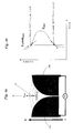
- FIG. 4 b is a graph illustrating a profile of dielectrophoretic force and an oblique component force of gravity
- FIG. 5 a is a graph illustrating forces acting upon a particle when the DEP device has been turned upside down
- FIG. 5 b is a graph illustrating a profile of dielectrophoretic force and the oblique component force of gravity, which are produced at this time;
- FIG. 6 illustrates forces acting upon a particle, in which the particle is shown displaced from a central axis and a resultant force is produced
- FIG. 7 illustrates forces acting upon a particle, in which the particle is shown displaced from a central axis and the forces are in balance
- FIG. 8 illustrates the placement relationship between a tilting plate and a rotary disk, namely the inclination of a DEP device
- FIG. 9 illustrates the placement relationship between a tilting plate and a rotary disk, namely the rotation of a DEP device
- FIG. 10 illustrates coordinate axes
- FIGS. 11 a and 11 b are graphs illustrating amounts of movement of a particle, with the passage of time, when an angle ⁇ pitch is changed suddenly from 60° to 15° and from 15° to 60°, respectively;
- FIG. 12 is a graph illustrating successive angular step responses over a plurality of times
- FIG. 13 a illustrates positions of a particle in angular step response
- FIG. 13 b is a graph illustrating a stable equilibrium point at every angle
- FIG. 14 is a graph illustrating a change in position of a static particle on which an oblique component force of gravity and dielectrophoretic force are in balance, with an angle ⁇ pitch being plotted along the horizontal axis;
- FIGS. 15 a and 15 b are graphs illustrating amounts of movement of a particle, with the passage of time, when voltage is changed suddenly from 8 Vpp to 20 Vpp and from 20 Vpp to 8 Vpp, respectively;
- FIG. 16 is a graph illustrating successive voltage step responses over a plurality of times
- FIG. 17 a illustrates positions of a particle in voltage step response
- FIG. 17 b is a graph illustrating a stable equilibrium point at every voltage
- FIG. 18 is a graph illustrating a change in position of a static particle on which an oblique component force of gravity and dielectrophoretic force are in balance, with a voltage Vpp being plotted along the horizontal axis;
- FIGS. 19 a and 19 b are graphs illustrating amounts of movement of a particle, with the passage of time, when a frequency f is changed suddenly from 300 KHz to 5 MHz and from 5 MHz to 300 KHz, respectively;
- FIG. 20 is a graph illustrating successive frequency step responses over a plurality of times
- FIG. 21 a illustrates positions of a particle in frequency step response
- FIG. 21 b is a graph illustrating a stable equilibrium point at every frequency
- FIG. 22 is a graph illustrating a change in position of a static particle on which an oblique component force of gravity and dielectrophoretic force are in balance, with a frequency f being plotted along the horizontal axis;
- FIG. 23 illustrates the manner in which a dielectric particle is moved (handled).
- FIG. 24 illustrates a state in which a plurality of dielectric particles have been separated
- FIG. 25 is a perspective view illustrating the overall configuration of a dielectrophoresis apparatus
- FIG. 26 is a perspective view illustrating the mounting structure of a tilting plate in a dielectrophoresis apparatus
- FIG. 27 is a side view illustrating a structure for fixing positioning of a tilting plate in a dielectrophoresis apparatus
- FIG. 28 is an enlarged sectional view taken along line a-a in FIG. 27 ;
- FIG. 29 is a perspective view illustrating the manner in which a rotary disk is provided on an XY table in a dielectrophoresis apparatus
- FIG. 30 is a sectional view illustrating the mounting structure of a rotary disk in a dielectrophoresis apparatus
- FIG. 31 is a block diagram illustrating the electrical configuration of a dielectrophoresis apparatus
- FIG. 32 is a plan view illustrating a modification of a DEP device, in which a portion of the device has been cut away.
- FIG. 33 is a longitudinal sectional view of FIG. 32 .
- Equation (2) Equation (3)
- E rms expresses the intensity of the alternating electric field as the root-mean-square value.
- R e ( f CM ) R e ⁇ ( ⁇ * p ⁇ * m )/( ⁇ * p +2 ⁇ * m ) ⁇ Eq. (2)
- ⁇ * p and ⁇ * m are the complex relative permittivities of the particle and solution, respectively.
- a dielectrophoretic force in the direction of a sparse electric field distribution acts upon the particle (this is referred to as “negative dielectrophoresis”)
- a dielectrophoretic force in the direction of a dense electric field distribution acts upon the particle (this is referred to as “positive dielectrophoresis”).
- Classification (filtering) and characteristic evaluation of uncharged particles in a solution particularly biological cells (normal cells and cancerous cells of erythrocytes and leukocytes, malaria-parasitized erythrocytes and various bacteria, etc.) and DNA cells, etc., are very difficult when particle size is several microns or less. Handling these target bodies also is not easy.
- the direction and magnitude of the dielectrophoretic force differ depending upon whether the permittivity of particles (inclusive of the above-mentioned biological cells) is larger or smaller than the permittivity of the solution (solvent), this makes possible the handling of particles, such as the moving and stopping of particles, the separation or sorting of mixed particles (inclusive of the above-mentioned biological cells) and the identification of specific particles (inclusive of the above-mentioned biological cells).
- DEP device dielectrophoresis device
- Appatus referred to as a “DEP device” below
- This DEP device is such that a frame serving as a spacer is secured to the periphery of a flat glass plate (lower plate), the interior of a space delimited by the spacer is filled with a solution, a particle is introduced into this space and this is covered from above by a flat cover glass (upper plate) to form a space (hermetically sealed) the interior of which is filled with the solution.
- Electrodes for forming a non-uniform alternating electric field inside the (hermetically sealed) space are provided on the glass plate, etc., although this will be described in detail later.
- ⁇ p represents the density of the particle
- ⁇ m the density of the solution
- g gravitational acceleration
- the DEP device set forth above is placed on an inclined surface. Let the tilt angle of the inclined surface be represented by ⁇ pitch , and let the direction upward along the inclined surface be the direction of the X axis.
- the component force of gravity F G directed downward parallel to the inclined surface is F G sin ⁇ pitch (this component will be referred to as the “oblique component force of gravity” below).
- F G sin ⁇ pitch this component will be referred to as the “oblique component force of gravity” below.
- a non-uniform alternating electric field is applied so that a dielectrophoretic force F DEP directed upward parallel to the inclined surface acts upon the particle in the solution. If these forces F G sin ⁇ pitch and F DEP are in balance, the particle will come to rest.
- Equation (4) the dielectrophoretic force F DEP can be measured using Equation (4) by producing a state in which Equation (4) holds. (This is referred to as the “null method”.) Further, if ⁇ 0 , ⁇ m and ⁇ p are known, then the value of intensity E of the electric field can be calculated from Equations (1) and (2).
- FIGS. 2 and 3 An example of the construction of a DEP device 10 is illustrated in FIGS. 2 and 3 .
- a pair of left and right electrodes (Creek-Gap electrodes) 13 A, 13 B are formed on the flat surface of a glass plate 11 substantially at the center thereof.
- the electrodes 13 A, 13 B are such that mutually opposing sides thereof first extend in parallel with a very small spacing between them over a length that is one-third to one-fourth of the electrode length, from one side, i.e., the right side in FIG. 3 (the side situated at the lower portion of the inclined surface when the device is placed on the inclined surface) (this side will be referred to as the “lower end” or “terminal side” below), to the other side, i.e., the left side in FIG.
- Wiring patterns extend from the lower ends of the respective electrodes 13 A, 13 B and lead to electrode terminals 13 a , 13 b formed at the terminus of the glass plate 11 .
- the electrodes 13 A and 13 B are line-symmetrical with respect to the center line N.
- the electrodes 13 A, 13 B, wiring patterns and terminals 13 a , 13 b can be obtained by forming an aluminum thin film on the surface of the glass plate 11 by sputtering and then patterning the thin film using photolithography.
- An insulating film 14 (e.g., photosensitive polyimide having a thickness of 1 ⁇ m or less) is formed on the surface of the glass plate 11 , inclusive of the electrodes 13 A, 13 B and their wiring patterns, and the surface of the film is flat and parallel to the surface of the glass plate 11 .
- the insulating film 14 is not formed on the right end portion of the glass plate 11 that includes the terminals 13 a , 13 b.
- a spacer 15 having a circular hole 15 A is placed on and fixed to the insulating film 14 .
- the position and size of the hole 15 A are decided in such a manner that the electrodes 13 A, 13 B fit completely into the hole 15 A.
- the spacer 15 can be fabricated from silicone rubber (having a thickness of 100 ⁇ m), by way of example.
- the hole 15 A in the spacer 15 is filled with dielectric solution S (e.g., distilled water) having the relative permittivity ⁇ m , and one or a plurality of dielectric particles P (e.g., polystyrene beads having a diameter of 9.9 ⁇ m) having the relative permittivity ⁇ p are introduced into the hole 15 A.
- dielectric solution S e.g., distilled water
- dielectric particles P e.g., polystyrene beads having a diameter of 9.9 ⁇ m
- a non-uniform alternating electric field is formed between the electrodes 13 A and 13 B (between the above-mentioned two sides of the electrodes) in the space defined by the hole 15 A and filled with the solution S.
- the permittivity of the polystyrene beads is less than that of the distilled water S. Accordingly, negative dielectrophoresis is produced, a dielectrophoretic force directed toward the larger electrode spacing acts upon the polystyrene beads (particles P) and the polystyrene beads travel in this direction (leftward in FIG. 3 ) if the DEP device 10 is placed in a horizontal attitude.
- Such DEP device 10 is placed on the inclined surface shown in FIG. 1 , the terminal side of the device being situated on the lower end.
- a single dielectric particle P exists on the center line N in the space within the DEP device 10 .
- the inclination of the center line N is ⁇ pitch .
- the dielectrophoretic force F DEP directed upward along the inclined surface and the oblique component force F G sin ⁇ pitch of gravity directed downward along the inclined surface act upon the particle P. This is illustrated in FIGS. 4 a and 4 b . In FIG.
- the dielectrophoretic force F DEP is indicated by the curve and the oblique component force F G sin ⁇ pitch of gravity is indicated by the straight line (and varies depending upon the tilt angle ⁇ itch ). Points of intersection between these two forces F DEP and F G sin ⁇ pitch are points (referred to as “equilibrium points”) where the two forces are in balance, as described above.
- the dielectrophoretic force F DEP exhibits a curve profile having a peak at its center, as illustrated in FIG. 4 b .
- the electric field strength is large because the spacing between the two electrodes 13 A and 13 B is very small. Since the opposing sides of the left and right electrodes 13 A, 13 B are parallel, the electric field is not inclined and, hence, no dielectrophoretic force is produced.
- the electrode spacing is very large, the electric field strength and its inclination are very small and the dielectrophoretic force is substantially zero. As a result, the dielectrophoretic force has the peak at its center.
- the upper one is a stable equilibrium point. That is, the dielectrophoretic force F DEP that acts upon a particle lower than this equilibrium point is greater than the oblique component force F G sin ⁇ pitch of gravity and the particle rises toward the equilibrium point.
- the dielectrophoretic force F DEP that acts upon a particle higher than this equilibrium point is smaller than the oblique component force F G sin ⁇ pitch of gravity and the particle falls toward the equilibrium point. Since the particle moves toward this equilibrium point in either case, this equilibrium point is a stable equilibrium point.
- the lower equilibrium point is an unstable equilibrium point because a particle that is above or below this equilibrium point is acted upon by a force that moves the particle in a direction away from this equilibrium point.
- FIG. 5 a illustrates the DEP device in a manner in which it has been placed on the inclined surface upside-down as compared with FIG. 4 a .
- FIG. 5 b illustrates the profile of the dielectrophoretic force that acts upon a dielectric particle at this time. In this case also two equilibrium points are produced and one of them is a stable equilibrium point.
- a DEP device having Creek-Gap electrodes is capable of assuring one stable equilibrium point and of bringing to rest (stopping) a particle in a stable state regardless of whether the dielectrophoretic force is positive or negative.
- the direction of the dielectrophoretic force F DEP is not parallel to the center line N but is inclined with respect to the center line N. Since the oblique component force F G sin ⁇ pitch of gravity acts in a direction parallel to the center line N, a resultant force C of these forces is produced and the particle P travels through the solution owing to the force C.
- the DEP device 10 is rotated on the inclined surface.
- a rotary disk 50 on which the DEP device 10 has been placed is rotated, as will be described later.
- the angle of rotation is represented by ⁇ yaw .
- the dielectrophoretic force F DEP and the oblique component force F G sin ⁇ pitch of gravity are balanced and the particle comes to rest (stops), as illustrated in FIG. 7 . That is, a stable equilibrium point exists in this case.
- Equation (4) holds at this time as well.
- the dielectrophoretic force F DEP can also be calculated by Equations (3), (4) using the conditions that prevail when the particle is at rest.
- tilting plate 30 that forms the inclined surface
- rotary disk 50 that holds the DEP device 10 and rotates it on the inclined surface (tilting plate 30 ) are all illustrated in FIGS. 8 to 10 in simple fashion in order to link to the dielectrophoresis apparatus described next.
- the direction along the tilting plate 30 is the X axis
- the direction perpendicularly intersecting the X axis and extending along the surface of the tilting plate 30 is the Y axis
- the direction orthogonal to the surface of the tilting plate 30 is the Z axis (this is a coordinate system different from the X and Y axes of an XY table 41 described later).
- the tilt angle ⁇ pitch of the tilting plate 30 corresponds to rotation about the Y axis.
- Rotation of the rotary disk 50 corresponds to rotation ⁇ yaw about the Z axis. It should be appreciated that the above-mentioned resultant force C can be cancelled by rotating the rotary disk 50 .
- the tilt angle ⁇ pitch of the tilting plate 30 is related to the magnitude of the dielectrophoretic force F DEP , and the rotation angle ⁇ yaw of the rotary disk 50 represents the direction of the dielectrophoretic force F DEP .
- FIGS. 25 to 31 An example of a dielectrophoresis apparatus is illustrated in FIGS. 25 to 31 .
- This dielectrophoresis apparatus can also be used as a dielectrophoretic force measurement apparatus, an apparatus for handling dielectric particles and an apparatus for sorting dielectric particles, and various methods (a dielectrophoretic force measurement method and methods of handling and sorting) can be implemented.
- the tilting plate 30 is pivotally attached at the lower edge thereof on a base 20 so as to be free to tilt. Specifically, a plurality of bearings 21 are secured on the base 20 . A plurality of mounting portions 32 in which shaft holes have been formed are formed as an integral part of the lower edge of the tilting plate 30 . A rotary shaft 31 is passed through the shaft holes of these mounting portions 32 and is fixed to the mounting portions. The shaft 31 is received in the bearings 31 in freely rotatable fashion. A rotation transducer (e.g., a potentiometer) 25 for detecting the angle of rotation of the rotary shaft 31 is mounted on the base 20 (or on one of the bearings 21 ).
- a rotation transducer e.g., a potentiometer
- a sector-shaped positioning plate 22 is provided on one side of the base 20 in an upright attitude perpendicular to the surface of the base 20 .
- a positioning groove 23 is formed in an arcuate shape in the positioning plate 22 near an arcuate edge thereof.
- a slide 33 in which threads have been formed and which protrudes slightly from the side of the tilting plate 30 is provided on one side of the tilting plate 30 at a location that moves along the positioning groove 23 as the tilting plate 30 is tilted.
- a lock screw 24 having a knob 24 a is inserted loosely into the positioning groove 23 from the outer side of the positioning plate 22 and is screwed into the threaded hole of the slide 33 .
- the tilting plate 30 forms the above-mentioned inclined surface.
- the tilting plate 30 can be brought to any angular position where the value of ⁇ pitch is between at least 0° and 90°.
- the tilting plate 30 can be secured at the positioned point by tightening the lock screw 24 .
- the angular position (the angle ⁇ pitch ) of the tilting plate 30 can be obtained in the form of an electrical signal by an output from the rotation transducer 25 or can be determined visually by providing the positioning plate 22 with angle graduations 22 A.
- the angle ⁇ pitch when the tilting plate 30 is horizontal is assumed to be 0°.
- an XY table mechanism 40 is secured on the tilting plate 30 .
- the XY table mechanism 40 has an XY table 41 on the upper portion thereof, and the position of the XY table 41 can be adjusted in the X and Y directions by knobs 42 , 43 .
- the surface of the XY table 41 is parallel to the surface of the tilting plate 30 .
- the X direction of the XY table mechanism 40 (the X direction in this coordinate system is different from the X direction along the inclined surface shown in FIG. 1 ) is a direction in the surface of the XY table 41 and parallel to the rotary shaft 31 of the tilting plate 30 .
- the Y direction is a direction in the surface of the XY table 41 and orthogonal to the X direction.
- the rotating mechanism will be described further with reference to FIGS. 29 and 30 .
- the XY table 41 is formed to have a circular recess 44 and the rotary disk 50 is freely rotatably inserted into the recess 44 . More specifically, a rotary shaft 52 secured to the lower portion of the rotary disk 50 at the center thereof is freely rotatably received in a bearing 45 provided on the XY table 41 .
- the XY table 41 is provided with a rotation transducer 46 for detecting the rotational angular position (the angle) of the rotary shaft 52 (i.e., the rotary disk 50 ).
- the XY table 41 is formed to have a positioning groove 47 at the periphery of the circular recess 44 along a range of angles greater than 180° ( ⁇ 90° to +90°).
- the positioning groove 47 is formed to have a large groove width at the lower portion thereof, and a slide 55 is inserted into the groove of large width so as to be freely slidable along the groove.
- a handle 53 extending diametrically outward is secured to the circumferential edge of the rotary disk 50 .
- the handle 53 is provided with a hole, a locking screw 54 having a knob 54 a is passed through the hole in freely rotatable fashion, and the distal end of the locking screw 54 is screwed into a threaded hole provided in the slide 55 .
- the rotary disk 50 can be rotated (over a range of at least ⁇ 90° to +90° manually using the handle 53 and can be fixed to the XY table 41 at any angular position by rotating the knob 54 a and then tightening the locking screw 54 .
- the angular position of the rotary disk 50 can be obtained in the form of an electrical signal from the rotation transducer 46 or can be read visually using graduation marks 41 A written (engraved) on the XY table 41 at a location along the periphery of the rotary disk 50 .
- the surface of the rotary disk 50 is formed to have a recess 51 for accommodating the DEP device 10 .
- the recess 51 is formed to have a size that will exactly accommodate the DEP device 10 (the recess 51 may just as well be larger than the DEP device 10 ), and the DEP device 10 that has been accommodated in the recess 51 cannot move with the exception of movement in the upward direction.
- the recess 51 is formed to have a cut-out 51 A for allowing the DEP device 10 to be removably inserted as by tweezers.
- Tabs 58 each comprising a leaf spring are rotatably attached to the rotary disk 50 by pins at a plurality of locations at the periphery of the recess 51 .
- the DEP device 10 accommodated in the recess 51 can be secured more strongly by the tabs 52 . It may of course be so arranged this fixing of the DEP device 10 is assured by introducing an adhesive or the like between the bottom face of the recess 51 and the underside of the DEP device 10 .
- the surface of the rotary disk 50 and the bottom face of the recess 51 are parallel to the surface of the XY table 41 and the surface of the tilting plate 30 . Accordingly, the tilt angle of the DEP device 10 (of the surfaces of the glass plate 11 and insulating film 14 ) accommodated in the recess 51 can be made equal to the tilt angle of the tilting plate 30 and can be measured as the tilt angle of the tilting plate 30 .
- the center line N of the electrodes 13 A, 13 B of DEP device 10 accommodated in the recess 51 coincides with the direction (the Y direction of the XY table 41 ) for which the angle of the tilted tilting plate 30 , XY table 41 and rotary disk 50 is largest.
- the angular position ( ⁇ yaw ) of the rotary disk 50 when the direction of the center line N coincides with the direction for which the angle is largest is 0°.
- a support 63 is secured on the tilting plate 30 and a microscope 60 is supported on the support 63 so as to be freely movable up and down (along the direction perpendicular to the surface of the tilting plate 30 ).
- the microscope 60 is placed at a position where the particle P within the DEP device 10 (e.g., the vicinity of the center of rotation of rotary disk 50 ) set on the rotary disk 50 can be received within the visual field.
- the position of the visual field of the microscope 60 can be adjusted by moving the XY table 41 along the X and Y directions using the XY table mechanism 40 . Focusing of the image of the visual field of microscope 60 can be adjusted by a knob 62 .
- the microscope 60 incorporates a CCD camera (indicated at 61 in FIG. 31 ) so that a video signal representing the image of the visual field can be obtained.
- the magnification of the microscope 60 can be adjusted as a matter of course.
- FIG. 31 illustrates an overview of the electrical configuration of the dielectrophoresis apparatus.
- a processing unit 70 which preferably is constituted by a computer system, when dielectrophoretic force, etc., is to be measured, accepts various inputs (described later), executes arithmetic processing in accordance with Equations (1) to (4) cited above, determines the dielectrophoretic force F DEP and intensity E of the electric field, etc., and outputs these to an output unit 72 (printer, display unit, etc.).
- a high-frequency generator 73 generates a high-frequency voltage applied across the electrodes 13 A, 13 B of the DEP device 10 .
- Frequency f and voltage V of this voltage are variable.
- the waveform of the high-frequency signal generated can be observed using an oscilloscope 75 .
- the frequency f and voltage V of the high-frequency voltage are applied to the processing unit 70 . It is also possible for the frequency f and voltage V to be read visually from the waveform display on the oscilloscope 75 . It may be so arranged that the processing unit 70 controls the high-frequency generator 73 and changes the frequency f and voltage V.
- the tilt angle ⁇ pitch of tilting plate 30 and angular position ⁇ yaw of rotary disk 50 detected by the rotation transducers 25 and 45 are input to the processing unit 70 via an interface 76 .
- These angles ⁇ pitch , ⁇ yaw can be read visually from the graduations 22 A, 41 A and can be input from an input unit 71 (keyboard, display unit and mouse).
- the video signal that is output from the CCD camera 61 inside the microscope 60 is displayed constantly (as a movie) on a display unit 74 .
- the video signal is converted to digital image data by the interface 76 as necessary and is applied to the processing unit 70 .
- the processing unit 70 can be programmed to apply image processing to the digital image data and determine whether the particle P is at rest or not.
- Parameters (particle radius r, solution density ⁇ m , particle density ⁇ p and acceleration g of gravitational force, etc.) necessary to calculate dielectrophoretic force F DEP are input to the processing unit 70 from the input unit 71 .
- Permittivity ⁇ 0 of air, relative permittivity of ⁇ m of the solution and relative permittivity ⁇ p of the particle also are input from the input unit 71 as necessary.
- a microscope control unit 77 for adjusting autofocus and magnification, etc. can be controlled by the processing unit 70 based upon the input digital image data, motors 78 , 79 for rotating the rotary shafts 31 , 52 can be provided and it can be so arranged that the angle ⁇ pitch of tilting plate 30 and angle ⁇ yaw of rotary disk 50 are adjusted so as to bring the particle P to rest under the control of the program executed by processing unit 70 .
- a high-frequency voltage (the frequency f and voltage V of which are made fixed values) is applied across the electrodes 13 A and 13 B of the DEP device 10 .
- the particle P can be moved or stopped (brought to rest) by changing the angle ⁇ pitch of the tilting plate 30 (i.e., the DEP device 10 ). Since the particle P comes to rest when the dielectrophoretic force F DEP acting upon the particle P and the oblique component force F G sin ⁇ pitch of gravity acting upon the particle P are in balance, the dielectrophoretic force F DEP can be found by Equations (3), (4) using the tilt angle ⁇ pitch prevailing at this time.
- the direction of the dielectrophoretic force F DEP is not a direction parallel to the central line N but is inclined with respect to the center line N. Since the oblique component force F G sin ⁇ pitch of gravity acts in a direction parallel to the center line N, a resultant force C of these forces is produced and the particle P is moved through the solution by the force C.
- the rotary disk 50 is rotated is such a manner that gravitational force will act in a direction that cancels the resultant force C.
- the dielectrophoretic force F DEP and oblique component force F G sin q pitch of gravity come into balance at a certain angular position ⁇ yaw of the rotary disk 50 , as illustrated in FIG. 7 . Since Equation (4) holds at this time as well, the dielectrophoretic force F DEP can be calculated using Equations (3), (4).
- the particle P at an arbitrary position G in the space within the DEP device 10 can also be moved to another desired position H and stopped at the position H, as illustrated in FIG. 23 .
- the most desirable option at this time is to change the tilt angle ⁇ pitch of the tilting plate 30 and the rotational angle ⁇ yaw of the rotary disk 50 , the voltage V or frequency f applied to the electrodes 13 A, 13 B may be changed just as well. (It may also be so arranged that the base 20 is tilted or rotated, as will be described later).
- the dielectrophoretic force F DEP is a function of the permittivity (relative permittivity) and radius of the particle P, as is evident from Equations (1), (2).
- P 1 , P 2 and P 3 represent particles of different permittivities or diameters, the particles being separated and positioned along the center line N.
- Particle handling and measurement of dielectrophoretic force F DEP takes on various forms from measurement by manual operation to measurement by automatic control.
- the tilt angle ⁇ pitch prevailing when the particle is brought to rest can be input manually from the input unit 71 and the processing unit 70 can be made to calculate the dielectrophoretic force F DEP .
- the dielectrophoretic force F DEP can be calculated from the tilt angle ⁇ pitch prevailing when the particle is brought to rest.
- the particle P can be moved or brought to rest also by changing the voltage V and frequency of the high-frequency signal applied across the electrodes 13 A and 13 B (or by holding the tilt angle ⁇ pitch fixed or by varying this angle) (the angle ⁇ yaw of the rotary disk 50 can be changed as necessary).
- the particle P was a polystyrene bead having a diameter of 9.9 ⁇ m, and the solution was distilled water.
- FIGS. 11 a , 11 b , 12 , 13 a , 13 b and 14 illustrate angular step response.
- Angular step response was obtained by varying the angle ⁇ pitch suddenly from 60° to 15° (from B to A) and from 15° to 60° (from A to B) under conditions of an applied voltage of 20 Vpp and frequency of 1 MHz (see FIGS. 12 , 13 a and 13 b ) and measuring the amount of movement of the particle.
- the time constant of movement from point B to point A is 3 min, and the time constant of movement from point A to point B is 1.9 min (see FIGS. 11 a and 11 b ).
- FIG. 14 is a graph illustrating a change in at-rest position (amount of movement) of a particle on which an oblique component force of gravity and dielectrophoretic force are in balance, with the angle ⁇ pitch being plotted along the horizontal axis. It will be understood that the larger the angle ⁇ pitch , the lower the position at which balance is achieved.
- the time constant of movement from point D to point C is 1 min, and the time constant of movement from point C to point D is 5 min (see FIGS. 15 a and 15 b ).
- the at-rest position moves upward as the voltage rises (see FIG. 18 ).
- the time constant of movement from point F to point E is 0.7 min, and the time constant of movement from point E to point F is 2.8 min (see FIGS. 19 a and 19 b ).
- the at-rest position moves upward as the voltage rises (see FIG. 22 ).
- the time constant in each step response is within several minutes and the steady state is achieved in about 15 min. This is a speed of response that can fully meet practical use.
- FIGS. 32 and 33 illustrate an example of a DEP device in which it is possible to broaden further the range of particle handling.
- This DEP device 10 A is the same as that shown in FIGS. 2 and 3 . Accordingly, an illustration of the details of the structure is omitted and only electrodes 13 A, 13 B are shown.
- the DEP device 10 A has a solution injection port 17 A at the center of one end thereof, and a solution discharge port 18 A at the center of the other end thereof. Connected to the solution injection port 17 A and solution discharge port 18 A are a solution injection tube 17 and discharge tube 18 , respectively, and the tubes 17 , 18 are provided with valves (cocks or valves) 17 B, 18 B, respectively.
- a particle suction port (trap port) 16 A is provided in a lower plate on the center line between the electrodes or at another suitable position, and a suction tube 16 is connected to this port.
- the DEP device 10 A can be used to sort only one particle from among a number of particles (small target bodies) that have been introduced into the DEP device. Specifically, by adjusting the angle ⁇ pitch or angle ⁇ yaw or the voltage or frequency (and the inclination or rotation of the base 20 if necessary) in the manner set forth above, a specific particle is made to move to the position of the suction port 16 A and is sucked in and saved in the suction tube 16 (or in a suitable trap connected thereto). Under these conditions the solution is injected into the DEP device 10 A from the injection port 17 A through the injection tube 17 and other particles present inside the device are discharged through the discharge port 18 A and discharge tube 18 .
- the specific particle that has been saved in the suction tube 16 is then returned to the interior of the DEP device 10 A.
- the specific particle is capable of being reserved inside the DEP device 10 A.
- the valves 17 B, 18 B are opened and closed when the solution is injected and discharged.
- the suction tube 16 may be provided with a valve as necessary.
- Particle movement can be speeded up by suddenly tilting or suddenly rotating the DEP device or by suddenly varying the voltage or frequency, as will be understood from the above-described step response.
- the base 20 may itself be rotated (through rotation ⁇ roll about the X axis when the X axis shown in FIG. 10 has been rotated through ⁇ pitch in the reverse direction and moved onto the base 20 ) as necessary, or the base 20 may be rotated in the direction of ⁇ pitch .
- a rotary disk is used in order to mount and rotate the DEP device.
- a disk-shaped body is not necessarily required.
- a rotary body having a shape suitable for supporting this should be used.
- a tilting body that is not plate-shaped can be used instead of the tilting plate of the tilting mechanism.
- the pair of electrodes 13 A, 13 B are used.
- multiple pairs of electrodes may be arranged longitudinally (along the vertical direction) in spaced-apart relation, or they may be arranged transversely. In the case of the transverse arrangement, two mutually adjacent electrodes (which belong to different pairs) may be integrated.
Landscapes
- Chemical & Material Sciences (AREA)
- Electrochemistry (AREA)
- Health & Medical Sciences (AREA)
- Life Sciences & Earth Sciences (AREA)
- Chemical Kinetics & Catalysis (AREA)
- Engineering & Computer Science (AREA)
- Molecular Biology (AREA)
- Microelectronics & Electronic Packaging (AREA)
- General Health & Medical Sciences (AREA)
- Environmental & Geological Engineering (AREA)
- Investigating Or Analyzing Materials By The Use Of Electric Means (AREA)
- Electrostatic Separation (AREA)
- Electrochromic Elements, Electrophoresis, Or Variable Reflection Or Absorption Elements (AREA)
Abstract
Description
- H. Li and R. Bashir, “Dielectrophoretic separation and manipulation of live and heat-treated cells of Listeria on microfabricated devices with interdigitated electrodes”, Sensors and Actuators B: Chemical, vol. 86, no. 2-3, pp. 215-221, 2002.
- P. Gascoyne, J. Satayavivad and M. Ruchirwat, “Microfluidic approaches to malaria detection”, Acta Tropica, vol. 89, pp. 357-369, 2004.
F DEP=2π∈0∈m r 3 Re(f CM)∇E 2 rms Eq. (1)
R e(f CM)=R e{(∈*p−∈*m)/(∈*p+2∈*m)} Eq. (2)
F G=(4/3)πr 3(ρp−ρm)g Eq. (3)
F DEP −F G sin θpitch=0 Eq. (4)
Claims (15)
Applications Claiming Priority (3)
| Application Number | Priority Date | Filing Date | Title |
|---|---|---|---|
| JP2007-262058 | 2007-10-05 | ||
| JP2007262058 | 2007-10-05 | ||
| PCT/JP2008/068114 WO2009044902A1 (en) | 2007-10-05 | 2008-09-26 | Dielectrophoresis device and method |
Publications (2)
| Publication Number | Publication Date |
|---|---|
| US20100219076A1 US20100219076A1 (en) | 2010-09-02 |
| US8864972B2 true US8864972B2 (en) | 2014-10-21 |
Family
ID=40526317
Family Applications (1)
| Application Number | Title | Priority Date | Filing Date |
|---|---|---|---|
| US12/681,616 Active 2030-09-23 US8864972B2 (en) | 2007-10-05 | 2008-09-26 | Dielectrophoresis apparatus and method |
Country Status (6)
| Country | Link |
|---|---|
| US (1) | US8864972B2 (en) |
| EP (1) | EP2204228A1 (en) |
| JP (1) | JP5120968B2 (en) |
| KR (1) | KR101162434B1 (en) |
| CN (1) | CN101820978B (en) |
| WO (1) | WO2009044902A1 (en) |
Cited By (5)
| Publication number | Priority date | Publication date | Assignee | Title |
|---|---|---|---|---|
| US20150306598A1 (en) * | 2014-04-25 | 2015-10-29 | Berkeley Lights, Inc. | DEP Force Control And Electrowetting Control In Different Sections Of The Same Microfluidic Apparatus |
| US10799865B2 (en) | 2015-10-27 | 2020-10-13 | Berkeley Lights, Inc. | Microfluidic apparatus having an optimized electrowetting surface and related systems and methods |
| US11007520B2 (en) | 2016-05-26 | 2021-05-18 | Berkeley Lights, Inc. | Covalently modified surfaces, kits, and methods of preparation and use |
| US11192107B2 (en) * | 2014-04-25 | 2021-12-07 | Berkeley Lights, Inc. | DEP force control and electrowetting control in different sections of the same microfluidic apparatus |
| US11365381B2 (en) | 2015-04-22 | 2022-06-21 | Berkeley Lights, Inc. | Microfluidic cell culture |
Families Citing this family (10)
| Publication number | Priority date | Publication date | Assignee | Title |
|---|---|---|---|---|
| KR101023040B1 (en) * | 2008-11-13 | 2011-03-24 | 한국항공대학교산학협력단 | High speed particle separation device and method |
| US20150306599A1 (en) | 2014-04-25 | 2015-10-29 | Berkeley Lights, Inc. | Providing DEP Manipulation Devices And Controllable Electrowetting Devices In The Same Microfluidic Apparatus |
| CN104165079B (en) * | 2014-08-22 | 2017-11-21 | 阮海生 | A kind of automobile tail gas purification system |
| WO2016094715A2 (en) | 2014-12-10 | 2016-06-16 | Berkeley Lights, Inc. | Movement and selection of micro-objects in a microfluidic apparatus |
| DE102018105931A1 (en) * | 2018-03-14 | 2019-09-19 | Technische Universität Darmstadt | Mikrowellenporator |
| CN111973737B (en) * | 2019-05-23 | 2022-08-26 | 比欧泰克生物技术服务(北京)有限公司 | Device and process for removing protein nucleic acid of capsular polysaccharide vaccine |
| WO2021157060A1 (en) * | 2020-02-07 | 2021-08-12 | 日本電信電話株式会社 | Device for arranging and conveying particles and method for arranging and conveying particles |
| EP4640818A1 (en) * | 2024-04-24 | 2025-10-29 | Fraunhofer-Gesellschaft zur Förderung der angewandten Forschung e.V. | Device, system and method for characterizing, separating, propagating and/or cryopreserving at least one biological cell |
| EP4640819A1 (en) * | 2024-04-24 | 2025-10-29 | Fraunhofer-Gesellschaft zur Förderung der angewandten Forschung e.V. | Device, system and method for characterizing, separating, propagating and/or cryopreserving at least one biological cell |
| CN121134948A (en) * | 2025-11-19 | 2025-12-16 | 陕西华浦环保科技有限公司 | An electromagnetically enhanced integrated water purification device |
Citations (16)
| Publication number | Priority date | Publication date | Assignee | Title |
|---|---|---|---|---|
| JP2001500252A (en) | 1996-07-26 | 2001-01-09 | ビーティージー・インターナショナル・リミテッド | Apparatus and method for testing particles using dielectrophoresis |
| JP2003066004A (en) | 2001-08-30 | 2003-03-05 | Matsushita Electric Ind Co Ltd | Particle separation method, particle separation device, and sensor |
| JP2003519176A (en) | 1999-12-29 | 2003-06-17 | クイーンズ ユニバーシティ アット キングストン | Methods and compositions for relieving pain |
| JP2003527601A (en) | 2000-03-10 | 2003-09-16 | アプレラ コーポレイション | Method and apparatus for locating and concentrating polar analytes using an alternating electric field |
| US6749736B1 (en) * | 1998-06-26 | 2004-06-15 | Evotec Technologies Gmbh | Electrode arrangement for the dielectrophoretic diversion of particles |
| JP2005506191A (en) | 2001-10-22 | 2005-03-03 | サントル ナショナル ドゥ ラ ルシェルシュ シアンティフィク | System for handling dielectric particles, especially biological cells, by dielectrophoresis |
| JP2005058840A (en) | 2003-08-19 | 2005-03-10 | Sumitomo Heavy Ind Ltd | Sludge concentrating method and sludge concentrating facility |
| US20050061962A1 (en) * | 2003-07-31 | 2005-03-24 | Arryx, Inc. | Multiple laminar flow-based rate zonal or isopycnic separation with holographic optical trapping of blood cells and other static components |
| JP2005224171A (en) | 2004-02-12 | 2005-08-25 | Masaru Hakoda | Method for analyzing dielectrophoretic activity and system therefor |
| JP2005291870A (en) | 2004-03-31 | 2005-10-20 | Kyokuhei Glass Kako Kk | Microchannel module |
| JP2006126195A (en) | 2001-03-22 | 2006-05-18 | Capital Biochip Co Ltd | Cell isolation method and use thereof |
| WO2007046484A1 (en) | 2005-10-19 | 2007-04-26 | Sharp Kabushiki Kaisha | Electrophoretic chip, electrophoretic device, and electrophoretic system |
| WO2007046485A1 (en) | 2005-10-19 | 2007-04-26 | Sharp Kabushiki Kaisha | Electrophoretic chip, electrophoretic device, and electrophoretic system |
| CN1990093A (en) | 2005-12-30 | 2007-07-04 | 财团法人工业技术研究院 | Multi-sample microfluidic dielectrophoretic separation device |
| WO2007091450A1 (en) | 2006-02-10 | 2007-08-16 | Kochi University Of Technology | Characteristic analyzing apparatus and method utilizing dielectric migration of granular substance by angularly modulated wave |
| US20100116665A1 (en) * | 2008-11-13 | 2010-05-13 | University Industry Cooperation Foundation Korea Aerospace University | System and method for high throughput particle separation |
Family Cites Families (1)
| Publication number | Priority date | Publication date | Assignee | Title |
|---|---|---|---|---|
| US20030102218A1 (en) * | 1997-07-28 | 2003-06-05 | Kiely James Dillon | Head-disk stiction reduction |
-
2008
- 2008-09-26 EP EP08835862A patent/EP2204228A1/en not_active Withdrawn
- 2008-09-26 KR KR1020107007173A patent/KR101162434B1/en not_active Expired - Fee Related
- 2008-09-26 CN CN2008801103224A patent/CN101820978B/en not_active Expired - Fee Related
- 2008-09-26 US US12/681,616 patent/US8864972B2/en active Active
- 2008-09-26 WO PCT/JP2008/068114 patent/WO2009044902A1/en not_active Ceased
- 2008-09-26 JP JP2009536128A patent/JP5120968B2/en active Active
Patent Citations (17)
| Publication number | Priority date | Publication date | Assignee | Title |
|---|---|---|---|---|
| JP2001500252A (en) | 1996-07-26 | 2001-01-09 | ビーティージー・インターナショナル・リミテッド | Apparatus and method for testing particles using dielectrophoresis |
| US6264815B1 (en) * | 1996-07-26 | 2001-07-24 | Btg International Limited | Apparatus and method for testing using dielectrophoresis |
| US6749736B1 (en) * | 1998-06-26 | 2004-06-15 | Evotec Technologies Gmbh | Electrode arrangement for the dielectrophoretic diversion of particles |
| JP2003519176A (en) | 1999-12-29 | 2003-06-17 | クイーンズ ユニバーシティ アット キングストン | Methods and compositions for relieving pain |
| JP2003527601A (en) | 2000-03-10 | 2003-09-16 | アプレラ コーポレイション | Method and apparatus for locating and concentrating polar analytes using an alternating electric field |
| JP2006126195A (en) | 2001-03-22 | 2006-05-18 | Capital Biochip Co Ltd | Cell isolation method and use thereof |
| JP2003066004A (en) | 2001-08-30 | 2003-03-05 | Matsushita Electric Ind Co Ltd | Particle separation method, particle separation device, and sensor |
| JP2005506191A (en) | 2001-10-22 | 2005-03-03 | サントル ナショナル ドゥ ラ ルシェルシュ シアンティフィク | System for handling dielectric particles, especially biological cells, by dielectrophoresis |
| US20050061962A1 (en) * | 2003-07-31 | 2005-03-24 | Arryx, Inc. | Multiple laminar flow-based rate zonal or isopycnic separation with holographic optical trapping of blood cells and other static components |
| JP2005058840A (en) | 2003-08-19 | 2005-03-10 | Sumitomo Heavy Ind Ltd | Sludge concentrating method and sludge concentrating facility |
| JP2005224171A (en) | 2004-02-12 | 2005-08-25 | Masaru Hakoda | Method for analyzing dielectrophoretic activity and system therefor |
| JP2005291870A (en) | 2004-03-31 | 2005-10-20 | Kyokuhei Glass Kako Kk | Microchannel module |
| WO2007046484A1 (en) | 2005-10-19 | 2007-04-26 | Sharp Kabushiki Kaisha | Electrophoretic chip, electrophoretic device, and electrophoretic system |
| WO2007046485A1 (en) | 2005-10-19 | 2007-04-26 | Sharp Kabushiki Kaisha | Electrophoretic chip, electrophoretic device, and electrophoretic system |
| CN1990093A (en) | 2005-12-30 | 2007-07-04 | 财团法人工业技术研究院 | Multi-sample microfluidic dielectrophoretic separation device |
| WO2007091450A1 (en) | 2006-02-10 | 2007-08-16 | Kochi University Of Technology | Characteristic analyzing apparatus and method utilizing dielectric migration of granular substance by angularly modulated wave |
| US20100116665A1 (en) * | 2008-11-13 | 2010-05-13 | University Industry Cooperation Foundation Korea Aerospace University | System and method for high throughput particle separation |
Non-Patent Citations (3)
| Title |
|---|
| Crane et al. J. Biol. Phys. (1977) 5:49-74. * |
| Haibo Li, et. al., "Dielectrophoretic separation and manipulation of live and heat-treated cells of Listeria on microfabricated devices with interdigitated electrodes", Sensors and Actuators B 86 (2002) 215-221. |
| Peter Gascoyne et. al., "Microfluidic approaches to malaria detection", Acta Tropica 89 (2004) 357-369. |
Cited By (13)
| Publication number | Priority date | Publication date | Assignee | Title |
|---|---|---|---|---|
| KR20160146975A (en) * | 2014-04-25 | 2016-12-21 | 버클리 라잇츠, 인크. | Dep force control and electrowetting control in different sections of the same microfluidic apparatus |
| CN106255888A (en) * | 2014-04-25 | 2016-12-21 | 伯克利照明有限公司 | DEP power in the different piece of same microfluidic device controls and electrowetting controls |
| CN106255888B (en) * | 2014-04-25 | 2019-12-10 | 伯克利之光生命科技公司 | DEP force control and electrowetting control in different sections of the same microfluidic device |
| KR102237846B1 (en) | 2014-04-25 | 2021-04-08 | 버클리 라잇츠, 인크. | Dep force control and electrowetting control in different sections of the same microfluidic apparatus |
| US20150306598A1 (en) * | 2014-04-25 | 2015-10-29 | Berkeley Lights, Inc. | DEP Force Control And Electrowetting Control In Different Sections Of The Same Microfluidic Apparatus |
| US11192107B2 (en) * | 2014-04-25 | 2021-12-07 | Berkeley Lights, Inc. | DEP force control and electrowetting control in different sections of the same microfluidic apparatus |
| US11365381B2 (en) | 2015-04-22 | 2022-06-21 | Berkeley Lights, Inc. | Microfluidic cell culture |
| US12134758B2 (en) | 2015-04-22 | 2024-11-05 | Bruker Cellular Analysis, Inc. | Microfluidic cell culture |
| US11964275B2 (en) | 2015-10-27 | 2024-04-23 | Berkeley Lights, Inc. | Microfluidic apparatus having an optimized electrowetting surface and related systems and methods |
| US10799865B2 (en) | 2015-10-27 | 2020-10-13 | Berkeley Lights, Inc. | Microfluidic apparatus having an optimized electrowetting surface and related systems and methods |
| US11007520B2 (en) | 2016-05-26 | 2021-05-18 | Berkeley Lights, Inc. | Covalently modified surfaces, kits, and methods of preparation and use |
| US11801508B2 (en) | 2016-05-26 | 2023-10-31 | Berkeley Lights, Inc. | Covalently modified surfaces, kits, and methods of preparation and use |
| US12280370B2 (en) | 2016-05-26 | 2025-04-22 | Bruker Cellular Analysis, Inc. | Covalently modified surfaces, kits, and methods of preparation and use |
Also Published As
| Publication number | Publication date |
|---|---|
| KR101162434B1 (en) | 2012-07-04 |
| JPWO2009044902A1 (en) | 2011-02-17 |
| CN101820978A (en) | 2010-09-01 |
| EP2204228A1 (en) | 2010-07-07 |
| KR20100051865A (en) | 2010-05-18 |
| CN101820978B (en) | 2013-01-09 |
| WO2009044902A1 (en) | 2009-04-09 |
| JP5120968B2 (en) | 2013-01-16 |
| US20100219076A1 (en) | 2010-09-02 |
Similar Documents
| Publication | Publication Date | Title |
|---|---|---|
| US8864972B2 (en) | Dielectrophoresis apparatus and method | |
| De Gasperis et al. | Automated electrorotation: dielectric characterization of living cells by real-time motion estimation | |
| US9423234B2 (en) | Mechanical phenotyping of single cells: high throughput quantitative detection and sorting | |
| Shields IV et al. | Field-directed assembly of patchy anisotropic microparticles with defined shape | |
| Delgado et al. | Measurement and interpretation of electrokinetic phenomena | |
| Frömer et al. | An experimental approach to the study of the sedimentation of dispersed particles in a centrifugal field | |
| Solsona et al. | Gradient in the electric field for particle position detection in microfluidic channels | |
| WO2005098395A1 (en) | Measuring device for impedance spectroscopy and associated measuring method | |
| Imasato et al. | Measurement of dielectrophoretic force by employing controllable gravitational force | |
| Goetz | An instrument for the quantitative separation and size-classification of air-borne particulate matter down to 0.2 micron | |
| CN109682745B (en) | Single cell parameter measuring method and device | |
| CN110579652A (en) | Method and device for measuring surface charge | |
| US20230236104A1 (en) | Device and method for measuring micro/nano-sized particles | |
| Zhbanov et al. | Electrochemical impedance spectroscopy of blood. Part 2: numerical analysis of experimental dielectric spectra using the biconcave shape of human erythrocytes | |
| Park et al. | Direct measurement of the dielectrophoresis forces acting on micro-objects using optical tweezers and a simple microfluidic chip | |
| CN211122430U (en) | Device for measuring micro-nano particles | |
| Benhal et al. | System identification and stochastic estimation of dielectric properties of a spherical particle using AC-induced electro-rotation | |
| KR101452930B1 (en) | Device for measuring contact angle and method for measuring contact angle | |
| Ren et al. | Effects of chip geometries on dielectrophoresis and electrorotation investigation | |
| Iiguni et al. | Simultaneous measurement of the migration velocity and adsorption force of micro-particles using an electromagnetophoretic force under a high magnetic field | |
| CN113740788A (en) | Device and method for measuring magnetic characteristics of object | |
| US20250035582A1 (en) | Apparatus to isolate external vibration for electrophoretic mobility measurement | |
| Glaser et al. | Electrorotation of single cells—A new method for assessment of membrane properties | |
| Zhao | An integrative approach to elucidating the governing mechanisms of particles movement under dielectrophoretic and other electrokinetic phenomena | |
| Talbott et al. | Aligning forces on wood particles in an electric field |
Legal Events
| Date | Code | Title | Description |
|---|---|---|---|
| AS | Assignment |
Owner name: KYUSHU INSTITUTE OF TECHNOLOGY, JAPAN Free format text: ASSIGNMENT OF ASSIGNORS INTEREST;ASSIGNORS:YAMAKAWA, TAKESHI;IMASATO, HIROKO;REEL/FRAME:024182/0509 Effective date: 20100317 |
|
| STCF | Information on status: patent grant |
Free format text: PATENTED CASE |
|
| FEPP | Fee payment procedure |
Free format text: PAYOR NUMBER ASSIGNED (ORIGINAL EVENT CODE: ASPN); ENTITY STATUS OF PATENT OWNER: SMALL ENTITY |
|
| MAFP | Maintenance fee payment |
Free format text: PAYMENT OF MAINTENANCE FEE, 4TH YR, SMALL ENTITY (ORIGINAL EVENT CODE: M2551) Year of fee payment: 4 |
|
| AS | Assignment |
Owner name: IMASATO, HIROKO, JAPAN Free format text: ASSIGNMENT OF ASSIGNORS INTEREST;ASSIGNOR:KYUSHU INSTITUTE OF TECHNOLOGY;REEL/FRAME:046581/0220 Effective date: 20180718 |
|
| MAFP | Maintenance fee payment |
Free format text: PAYMENT OF MAINTENANCE FEE, 8TH YR, SMALL ENTITY (ORIGINAL EVENT CODE: M2552); ENTITY STATUS OF PATENT OWNER: SMALL ENTITY Year of fee payment: 8 |
|
| MAFP | Maintenance fee payment |
Free format text: PAYMENT OF MAINTENANCE FEE, 12TH YR, SMALL ENTITY (ORIGINAL EVENT CODE: M2553); ENTITY STATUS OF PATENT OWNER: SMALL ENTITY Year of fee payment: 12 |