US8856744B2 - HDMI-muxed debug cable methods and apparatuses - Google Patents
HDMI-muxed debug cable methods and apparatuses Download PDFInfo
- Publication number
- US8856744B2 US8856744B2 US13/223,017 US201113223017A US8856744B2 US 8856744 B2 US8856744 B2 US 8856744B2 US 201113223017 A US201113223017 A US 201113223017A US 8856744 B2 US8856744 B2 US 8856744B2
- Authority
- US
- United States
- Prior art keywords
- hdmi
- line
- cable
- debug
- controller
- Prior art date
- Legal status (The legal status is an assumption and is not a legal conclusion. Google has not performed a legal analysis and makes no representation as to the accuracy of the status listed.)
- Active, expires
Links
Images


Classifications
-
- G—PHYSICS
- G09—EDUCATION; CRYPTOGRAPHY; DISPLAY; ADVERTISING; SEALS
- G09G—ARRANGEMENTS OR CIRCUITS FOR CONTROL OF INDICATING DEVICES USING STATIC MEANS TO PRESENT VARIABLE INFORMATION
- G09G3/00—Control arrangements or circuits, of interest only in connection with visual indicators other than cathode-ray tubes
- G09G3/006—Electronic inspection or testing of displays and display drivers, e.g. of LED or LCD displays
-
- G—PHYSICS
- G06—COMPUTING; CALCULATING OR COUNTING
- G06F—ELECTRIC DIGITAL DATA PROCESSING
- G06F11/00—Error detection; Error correction; Monitoring
- G06F11/30—Monitoring
- G06F11/3089—Monitoring arrangements determined by the means or processing involved in sensing the monitored data, e.g. interfaces, connectors, sensors, probes, agents
-
- G—PHYSICS
- G06—COMPUTING; CALCULATING OR COUNTING
- G06F—ELECTRIC DIGITAL DATA PROCESSING
- G06F11/00—Error detection; Error correction; Monitoring
- G06F11/36—Preventing errors by testing or debugging software
- G06F11/362—Software debugging
- G06F11/3648—Software debugging using additional hardware
-
- G—PHYSICS
- G09—EDUCATION; CRYPTOGRAPHY; DISPLAY; ADVERTISING; SEALS
- G09G—ARRANGEMENTS OR CIRCUITS FOR CONTROL OF INDICATING DEVICES USING STATIC MEANS TO PRESENT VARIABLE INFORMATION
- G09G2330/00—Aspects of power supply; Aspects of display protection and defect management
- G09G2330/02—Details of power systems and of start or stop of display operation
-
- G—PHYSICS
- G09—EDUCATION; CRYPTOGRAPHY; DISPLAY; ADVERTISING; SEALS
- G09G—ARRANGEMENTS OR CIRCUITS FOR CONTROL OF INDICATING DEVICES USING STATIC MEANS TO PRESENT VARIABLE INFORMATION
- G09G2370/00—Aspects of data communication
- G09G2370/04—Exchange of auxiliary data, i.e. other than image data, between monitor and graphics controller
- G09G2370/042—Exchange of auxiliary data, i.e. other than image data, between monitor and graphics controller for monitor identification
-
- G—PHYSICS
- G09—EDUCATION; CRYPTOGRAPHY; DISPLAY; ADVERTISING; SEALS
- G09G—ARRANGEMENTS OR CIRCUITS FOR CONTROL OF INDICATING DEVICES USING STATIC MEANS TO PRESENT VARIABLE INFORMATION
- G09G2370/00—Aspects of data communication
- G09G2370/12—Use of DVI or HDMI protocol in interfaces along the display data pipeline
Definitions
- Computing devices have made significant contributions toward the advancement of modern society and are utilized in a number of applications to achieve advantageous results.
- Numerous devices such as personal computers, laptop computers, tablet computers, smart phones and the like are directed toward specific markets and applications.
- the desktop PCs are generally able to operate with a large number of external peripheral devices, such as monitors, keyboards, pointing devices, printers, cameras, speakers and the like.
- the desktop PC are generally adapted to be readily expanded and/or upgraded.
- Laptop computers, tablet computers and smart phones provide increasing portability but generally are adapted to support fewer external peripheral devices, particularly at any given time and it generally is more difficult to upgrade or expand the devices.
- Most conventional computing devices include a plurality of ports for communicating with one or more peripheral device and/or one or more other devices.
- a conventional laptop computer may include an HDMI port, a DVI port, a plurality of USB ports, an Ethernet port, a WIFI transceiver, and/or the like.
- a conventional tablet computer may include one HDMI port, one USB port, a WIFI transceiver and/or the like.
- the smaller the form fact of the computing device the less communication ports are included.
- one or more peripherals such as a keyboard, a pointing device, speakers, a camera, a storage device and the like are coupled to the computing device through the USB port of the computing device.
- the operation of the computing device or between the computing device and one or more USB coupled peripheral device, and/or software running on the computing device or USB peripheral may experience problems.
- one of the ports may be used to debug the problem.
- one USB port can be used for normal USB operations while a debug platform can be coupled to another USB port for debugging the software or hardware of the computing device.
- Embodiments of the present technology are directed toward cables adapted for multiplexing debug commands and data on a high-definition multimedia interface (HDMI) when a computing device includes a single universal serial bus (USB).
- the a high-definition multimedia interface (HDMI) cable includes a pull up from a hot plug detect line to a power line, a static memory including an extended display identification data (EDID) code indicating a debug cable or debug host device, and serial input (RXD) and a serial output (TXD) lines.
- EDID extended display identification data
- RXD serial input
- TXD serial output
- a high-definition multimedia interface (HDMI) cable includes a pull up from an HDMI hot plug detect line to an HDMI power line, a static memory to receive a query and output an extended display identification data (EDID) code indicating a debug cable or debug host device on an HDMI SCL line and an HDMI SDA lines, and an HDMI serial input (RXD) line and an HDMI serial output (TXD) line to transmit and receive debug commands and data.
- EDID extended display identification data
- FIG. 1 shows a block diagram of an exemplary computing device, in accordance with one embodiment of the present technology.
- FIG. 2 shows a block diagram of a display engine with muxed HDMI controller, in accordance with one embodiment of the present technology.
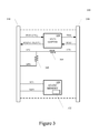
- FIG. 3 shows a block diagram of a HDMI cable adapted for debugging, in accordance with one embodiment of the present technology.
- FIG. 4 shows a muxed HDMI for use in a debugging system, in accordance with one embodiment of the present technology.
- routines, modules, logic blocks, and other symbolic representations of operations on data within one or more electronic devices are presented in terms of routines, modules, logic blocks, and other symbolic representations of operations on data within one or more electronic devices.
- the descriptions and representations are the means used by those skilled in the art to most effectively convey the substance of their work to others skilled in the art.
- a routine, module, logic block and/or the like is herein, and generally, conceived to be a self-consistent sequence of processes or instructions leading to a desired result.
- the processes are those including physical manipulations of physical quantities.
- these physical manipulations take the form of electric or magnetic signals capable of being stored, transferred, compared and otherwise manipulated in an electronic device.
- these signals are referred to as data, bits, values, elements, symbols, characters, terms, numbers, strings, and/or the like with reference to embodiments of the present technology.
- the use of the disjunctive is intended to include the conjunctive.
- the use of definite or indefinite articles is not intended to indicate cardinality.
- a reference to “the” object or “a” object is intended to denote also one of a possible plurality of such objects. It is also to be understood that the phraseology and terminology used herein is for the purpose of description and should not be regarded as limiting.
- Embodiments of the present technology are directed toward using an HDMI port of a device having a single USB port to allow debugging by a second computing device.
- the techniques multiplex the use of the HDMI port to allow debugging of the device without increasing the number of USB ports.
- the exemplary computing platform may include one or more central processing units (CPUs) 105 , one or more graphics processing units (GPUs) (not shown), volatile and/or non-volatile memory (e.g., computer readable media) 110 , 115 , a input/output controller hub 120 , one or more internal peripheral devices 125 , 130 , one or more HDMI ports 134 , and a single USB port communicatively coupled by one or more busses.
- CPUs central processing units
- GPUs graphics processing units
- volatile and/or non-volatile memory e.g., computer readable media
- the input/output controller hub 120 is adapted to communicate data and instructions between the CPU 105 , the computing device-readable media 110 , 115 , the one or more internal peripheral devices 125 , 130 , the one or more HDMI ports 134 , and the single USB port.
- the internal peripheral devices 125 , 130 may include a display 125 , a keyboard 130 , a pointing device, a speaker, a microphone, a wireless network radio (e.g., WIFI card) and/or the like.
- the computing device-readable media 110 , 115 may be characterized as primary memory and secondary memory.
- the secondary memory such as a solid state (e.g., flash memory), magnetic and/or optical mass storage, provides for non-volatile storage of computer-readable instructions and data for use by the computing device.
- the flash memory drive 115 may store the operating system (OS) 150 , applications (e.g., programs, drivers, routines, utilities) and data 155 .
- the primary memory such as the system memory 110 and/or graphics memory (not shown), provides for volatile storage of computer-readable instructions and data for use by the computing device.
- the system memory 110 may temporarily store all or a portion of the operating system 150 ′, and all or a portion of one or more applications and associated data 155 ′ that are currently used by the CPU 105 , GPU and the like.
- the input/output controller hub 120 may be implemented as an integral sub-circuit (e.g., single IC chip), or as one or more sub-circuits (e.g., a plurality of IC chips, such as a north and south bridge chip set).
- the input/output controller hub 120 may include a display engine 122 , a USB controller 124 , memory controllers, other peripheral controllers, and/or the like.
- the display engine 120 may include a muxed HDMI controller 122 .
- the muxed HDMI controller 122 may be implemented as a single sub-circuit (e.g., system-on-a-chip (SOIC)) or as one or more sub-circuit.
- SOIC system-on-a-chip
- the muxed HDMI controller 210 may include a universal asynchronous receiver/transmitter (UART) 212 , an HDMI module 214 and an isolation/level shifter circuit 216 . It is appreciated that the muxed HDMI controller 210 may be implemented by one or more separate and/or integral sub-circuits.
- the UART 212 and HDMI module 214 may be implemented by a system-on-an-integrated-circuit (SOIC), while the isolation/level shifter circuit 216 may be implemented by a separate integrated circuit, such as Texas Instrument's TX0102 voltage translation circuit IC.
- SOIC system-on-an-integrated-circuit
- the circuit isolation and/or signal level shifting of the isolation/level shifter circuit 216 may be controlled by an output enable signal from the UART 212 .
- the functional blocks of the muxed HDMI controller 210 may be implemented in any other of a number of arrangements of separate and/or integral sub-circuits in accordance with embodiments of the present technology.
- the HDMI controller provides connections at the HDMI port 135 that include a consumer electronics control (CEC) line (e.g., serial output (TXD)), a serial input (RXD) (also known as the reserved, utility or HEC—according to the HDMI standard), ground (not shown) and power lines, a hot plug detect line, a display data channel bus (e.g., transition minimized differential signaling (TMDS) lines), and serial clock line (SCL) and serial data lines (SDA).
- CEC consumer electronics control
- TXD serial output
- RXD serial input
- ground not shown
- power lines e.g., ground (not shown) and power lines
- a hot plug detect line e.g., a display data channel bus (e.g., transition minimized differential signaling (TMDS) lines), and serial clock line (SCL) and serial data lines (SDA).
- TMDS transition minimized differential signaling
- SCL serial clock line
- SDA serial data lines
- the muxed HDMI controller 210 is also adapted to transmit and receive debugging commands and data through the HDMI port 135 .
- the HDMI module 214 detects a hot plug device signal on the HPD line, the HDMI module 214 reads extended display identification data (EDID) across the SCL and SDA lines. If the EDID is a unique code indicating a “debug” cable or hostdevice, the HDMI module 214 disables (e.g., high impedance state) the display data channel bus (e.g., transition minimized differential signaling (TMDS) lines). Thereafter, the debug commands and data are transmitted and received across the serial input (RXD) and output (TXD) lines of the HDMI port 135 by the UART 212 and isolation/level shifter circuit 216 .
- EDID extended display identification data
- TMDS transition minimized differential signaling
- the serial input (RXD) and output (TXD) lines are left in a high impedance state, and the line level is typically used at 1.8V, although any voltage is usable. If another line level is appropriate, the signals on the serial input (RXD) and output (TXD) lines are line leveled with one of the other voltages commonly used by the HDMI connector for these pins. To avoid incompatibility with a conventional HDMI cable assembly that is being inserted into the socket, the outputs of the isolation/level shifter circuit 216 are held in a high impedance state until such time as the muxed HDMI controller 210 enables the debugging state.
- the HDMI cable includes an HDMI connector 310 , a consumer electronics control (CEC) line (e.g., serial output (TXD)), a serial input (RXD), ground (not shown) and power (e.g., 5V) lines, a hot plug detect (HPD) line, SCL and SDA lines, static memory 320 and a debug connector 330 .
- CEC consumer electronics control
- TXD serial output
- RXD serial input
- HPD hot plug detect
- SCL and SDA static memory
- static memory 320 static memory
- debug connector 330 e.g., static memory 320
- the HPD line is coupled to provide a pull-up 340 to the power line.
- a resistive element may provide the pull-up 340 from the HPD line to the power line.
- the static memory 320 such as a 12C EEPROM or ROM, is coupled to the SCL and SDA lines.
- the static memory 320 includes a unique EDID code 322 indicating a “debug” host mode/device.
- the HDMI cable may optionally include a level shifter circuit 350 in the consumer electronics control (CEC line (e.g., serial output (TXD)) and the serial input (RXD) line.
- the optional level shifter circuit 340 is adapted to translate the voltage line levels from one logic level to another.
- One or more lines of the HDMI cable may optionally include short circuit protection 360 , such as a resistive element.
- the debug connector 330 may be any conventional connector, such as a DB-9 connector, for coupling to a host debugging computing, system. If the cable is designed for use with a TTL compatible serial device such as another UART, then the signals could be passed through the cable without further electrical modification. In another implementation, a RS232 level converter can be used such that the serial connection is then made available with personal computer (PC) compatible signaling levels still using passive components that require no configuration.
- PC personal computer
- FIG. 4 shows a muxed HDMI for use in a debugging system.
- the system includes a target computing device 100 communicatively coupled by an HDMI cable adapted for debugging 300 to a host debugging computing device 410 .
- the target debug computing device 100 includes a single USB port 140 , and an HDMI port 135 .
- a muxed HDMI controller 212 - 216 of the target computing device 110 detects a hot plug detect signal when the HDMI cable adapted for debugging 300 is coupled to its HDMI port 135 .
- the conventional hot plug detection circuitry is used allowing unchanged design from a platform that does not support muxed HDMI debugging.
- the muxed HDMI controller 212 - 216 of the target computing device 100 reads an EDID code across the SCL and SDA lines from a static memory 320 of the HDMI cable assembly 300 .
- the unique EDID code indicates the presence of an HDMI cable adapted for debugging and/or a “debug” host device, and not to standard HDMI sink.
- the static memory may optionally include information about the cable to allow for further configuration of the debug host 410 .
- the muxed HDMI controller 212 - 216 In response to the “debug” cable/host device EDID code, the muxed HDMI controller 212 - 216 disables the TMDS data bus.
- the muxed HDMI controller 212 - 216 also enables transmission and receipt of debug commands and data across the consumer electronics control (CEC) line (e.g., serial output (TXD)) and the serial input (RXD) line, in response to the “debug” host mode/device EDID code.
- the debugging computing device 410 may be acting substantially similar to a USB host and the target computing device 100 may be acting substantially similar to a USB slave/bridge device.
- embodiments of the present technology advantageously allow debugging a device without increasing the number of USB ports that are on the chassis or affecting the final height (z) of the chassis.
Priority Applications (2)
| Application Number | Priority Date | Filing Date | Title |
|---|---|---|---|
| US13/223,017 US8856744B2 (en) | 2011-08-31 | 2011-08-31 | HDMI-muxed debug cable methods and apparatuses |
| TW101131127A TWI493335B (zh) | 2011-08-31 | 2012-08-28 | 多工hdmi除錯排線之方法與設備 |
Applications Claiming Priority (1)
| Application Number | Priority Date | Filing Date | Title |
|---|---|---|---|
| US13/223,017 US8856744B2 (en) | 2011-08-31 | 2011-08-31 | HDMI-muxed debug cable methods and apparatuses |
Publications (2)
| Publication Number | Publication Date |
|---|---|
| US20130048372A1 US20130048372A1 (en) | 2013-02-28 |
| US8856744B2 true US8856744B2 (en) | 2014-10-07 |
Family
ID=47742014
Family Applications (1)
| Application Number | Title | Priority Date | Filing Date |
|---|---|---|---|
| US13/223,017 Active 2031-10-04 US8856744B2 (en) | 2011-08-31 | 2011-08-31 | HDMI-muxed debug cable methods and apparatuses |
Country Status (2)
| Country | Link |
|---|---|
| US (1) | US8856744B2 (zh) |
| TW (1) | TWI493335B (zh) |
Cited By (3)
| Publication number | Priority date | Publication date | Assignee | Title |
|---|---|---|---|---|
| US9003369B2 (en) | 2011-08-31 | 2015-04-07 | Nvidia Corporation | HDMI-muxed debug port methods and apparatuses |
| US10535961B2 (en) | 2016-04-26 | 2020-01-14 | Ryan E. Cote | Electrical cables having integrated and manually controllable identification and illumination light sources |
| US10817405B2 (en) | 2018-01-19 | 2020-10-27 | Samsung Electronics Co., Ltd. | Storage device and debugging system thereof |
Families Citing this family (7)
| Publication number | Priority date | Publication date | Assignee | Title |
|---|---|---|---|---|
| US9274992B2 (en) * | 2013-07-19 | 2016-03-01 | Lattice Semiconductor Corporation | Cable with circuitry for communicating performance information |
| US9870301B2 (en) * | 2014-03-31 | 2018-01-16 | Intel Corporation | High-speed debug port using standard platform connectivity |
| CN108804274A (zh) * | 2017-04-26 | 2018-11-13 | 精英电脑股份有限公司 | 检错装置 |
| JP2019046066A (ja) * | 2017-08-31 | 2019-03-22 | 株式会社東芝 | 電子装置及びケーブル |
| CN112419952B (zh) * | 2019-08-21 | 2022-04-26 | 京东方科技集团股份有限公司 | 一种移位寄存器及其驱动方法、栅极驱动电路 |
| CN110618672A (zh) * | 2019-10-18 | 2019-12-27 | 深圳市道通科技股份有限公司 | 一种接口电路及其接口通信的方法、装置 |
| CN117055966A (zh) * | 2023-10-13 | 2023-11-14 | 深圳中微电科技有限公司 | 基于hdmi的热插拔检测与处理方法、装置及存储介质 |
Citations (5)
| Publication number | Priority date | Publication date | Assignee | Title |
|---|---|---|---|---|
| US20040027515A1 (en) * | 2002-08-09 | 2004-02-12 | Nec-Mitsubishi Electric Visual Systems Corporation | Display apparatus, display system and cable |
| US20050182876A1 (en) * | 2004-02-18 | 2005-08-18 | Silicon Image, Inc. | Cable with circuitry for asserting stored cable data or other information to an external device or user |
| US20060031611A1 (en) * | 2004-08-05 | 2006-02-09 | Sumitomo Electric Industries, Ltd. | Digital video signal interface module |
| US20060277586A1 (en) * | 2005-05-20 | 2006-12-07 | Fuji Xerox Co., Ltd. | Signal communication apparatus and signal communication system |
| US20120064758A1 (en) * | 2010-09-09 | 2012-03-15 | Grice Michael E | HDMI Plug and Cable Assembly |
Family Cites Families (3)
| Publication number | Priority date | Publication date | Assignee | Title |
|---|---|---|---|---|
| TWI301699B (en) * | 2005-10-18 | 2008-10-01 | Sunplus Technology Co Ltd | Transmitting circuit, receiving circuit, interface switching module and interface switching method for sata and sas interface |
| KR101432846B1 (ko) * | 2006-11-07 | 2014-08-26 | 소니 주식회사 | 전자기기 및 케이블 장치 |
| CN101282413A (zh) * | 2008-04-11 | 2008-10-08 | 青岛海信电器股份有限公司 | Hdmi串口通信电路 |
-
2011
- 2011-08-31 US US13/223,017 patent/US8856744B2/en active Active
-
2012
- 2012-08-28 TW TW101131127A patent/TWI493335B/zh active
Patent Citations (5)
| Publication number | Priority date | Publication date | Assignee | Title |
|---|---|---|---|---|
| US20040027515A1 (en) * | 2002-08-09 | 2004-02-12 | Nec-Mitsubishi Electric Visual Systems Corporation | Display apparatus, display system and cable |
| US20050182876A1 (en) * | 2004-02-18 | 2005-08-18 | Silicon Image, Inc. | Cable with circuitry for asserting stored cable data or other information to an external device or user |
| US20060031611A1 (en) * | 2004-08-05 | 2006-02-09 | Sumitomo Electric Industries, Ltd. | Digital video signal interface module |
| US20060277586A1 (en) * | 2005-05-20 | 2006-12-07 | Fuji Xerox Co., Ltd. | Signal communication apparatus and signal communication system |
| US20120064758A1 (en) * | 2010-09-09 | 2012-03-15 | Grice Michael E | HDMI Plug and Cable Assembly |
Non-Patent Citations (6)
| Title |
|---|
| "Communication interface circuit for on-line emulation and debugging, has set of sending/receiving switching channels in protocol level shifter circuit, and channel's output end connected with serial port's data receiving terminal" CN 200976142 Y, Nov. 14, 2007. * |
| Debugging-Wikipedia, the free encyclopedia, Aug. 23, 2011, http://web.archive.org/web/20110913013559/http://en.wikipedia.org/wiki/Debugging. * |
| Debugging—Wikipedia, the free encyclopedia, Aug. 23, 2011, http://web.archive.org/web/20110913013559/http://en.wikipedia.org/wiki/Debugging. * |
| Digital Visual Interface-Wikepedia, the three encyclopedia, Feb. 9, 2010, http://web.archive.org/web/20100209004631/http://en.wikipedia.org/wiki/Digital-Visual-Interface. * |
| Digital Visual Interface—Wikepedia, the three encyclopedia, Feb. 9, 2010, http://web.archive.org/web/20100209004631/http://en.wikipedia.org/wiki/Digital—Visual—Interface. * |
| HDMI-based debug module, Leonard Tsai, Jan. 2011, Research Disclosure databased No. 561059. * |
Cited By (3)
| Publication number | Priority date | Publication date | Assignee | Title |
|---|---|---|---|---|
| US9003369B2 (en) | 2011-08-31 | 2015-04-07 | Nvidia Corporation | HDMI-muxed debug port methods and apparatuses |
| US10535961B2 (en) | 2016-04-26 | 2020-01-14 | Ryan E. Cote | Electrical cables having integrated and manually controllable identification and illumination light sources |
| US10817405B2 (en) | 2018-01-19 | 2020-10-27 | Samsung Electronics Co., Ltd. | Storage device and debugging system thereof |
Also Published As
| Publication number | Publication date |
|---|---|
| TWI493335B (zh) | 2015-07-21 |
| US20130048372A1 (en) | 2013-02-28 |
| TW201324133A (zh) | 2013-06-16 |
Similar Documents
| Publication | Publication Date | Title |
|---|---|---|
| US8856744B2 (en) | HDMI-muxed debug cable methods and apparatuses | |
| US9003369B2 (en) | HDMI-muxed debug port methods and apparatuses | |
| US10216683B2 (en) | Multimedia communication apparatus and control method for multimedia data transmission over standard cable | |
| CN107111588B (zh) | 经由USB端口使用PCIe协议的数据传输 | |
| US7921233B2 (en) | Signal converter for an all-in-one USB connector that includes USB 2.0, USB 3.0 and eSATA | |
| US20160004287A1 (en) | Portable electronic device and power management method thereof | |
| JP5009519B2 (ja) | フラットパネルコントローラ中の仮想拡張ディスプレイ識別データ(edid) | |
| US11624788B2 (en) | Display module test platform | |
| EP2589205B1 (en) | Detection of cable connections for electronic devices | |
| US7839409B2 (en) | Acquisition of extended display identification data (EDID) using inter-IC (I2C) protocol | |
| EP2040174B1 (en) | Card-type peripheral device | |
| USH2186H1 (en) | Acquisition of extended display identification data (EDID) in a display controller in a power up mode from a power down mode | |
| US7484112B2 (en) | Power management in a display controller | |
| CN109313466B (zh) | 用于在pci卡上实施mxm的系统 | |
| US7477244B2 (en) | Automatic activity detection in a display controller | |
| US20060082586A1 (en) | Arbitration for acquisition of extended display identification data (EDID) | |
| JP2011166720A (ja) | 複数バージョンのusbと互換性があるマザーボード及び関連方法 | |
| US11151065B2 (en) | Method for performing detection control of write protection function of memory device, associated control chip and associated electronic device | |
| US20150350592A1 (en) | Electronic device and video data receiving method thereof | |
| US9710875B2 (en) | Image transmission apparatus and image processing method thereof | |
| US11609622B2 (en) | Ground and supply cable compensation architecture for USB power delivery subsystem | |
| JP5107205B2 (ja) | ディスプレイ接続用のアダプタおよびディスプレイ接続システム | |
| US20090153467A1 (en) | System and method for connection detection | |
| US8347013B2 (en) | Interface card with extensible input/output interface | |
| US20170220069A1 (en) | Docking apparatus and control method thereof |
Legal Events
| Date | Code | Title | Description |
|---|---|---|---|
| AS | Assignment |
Owner name: NVIDIA CORPORATION, CALIFORNIA Free format text: ASSIGNMENT OF ASSIGNORS INTEREST;ASSIGNOR:OVERBY, MARK ALAN;REEL/FRAME:026841/0283 Effective date: 20110831 |
|
| STCF | Information on status: patent grant |
Free format text: PATENTED CASE |
|
| MAFP | Maintenance fee payment |
Free format text: PAYMENT OF MAINTENANCE FEE, 4TH YEAR, LARGE ENTITY (ORIGINAL EVENT CODE: M1551) Year of fee payment: 4 |
|
| MAFP | Maintenance fee payment |
Free format text: PAYMENT OF MAINTENANCE FEE, 8TH YEAR, LARGE ENTITY (ORIGINAL EVENT CODE: M1552); ENTITY STATUS OF PATENT OWNER: LARGE ENTITY Year of fee payment: 8 |