US8847526B2 - Methods and systems for automatic rotation direction determination of electronically commutated motor - Google Patents
Methods and systems for automatic rotation direction determination of electronically commutated motor Download PDFInfo
- Publication number
- US8847526B2 US8847526B2 US13/942,253 US201313942253A US8847526B2 US 8847526 B2 US8847526 B2 US 8847526B2 US 201313942253 A US201313942253 A US 201313942253A US 8847526 B2 US8847526 B2 US 8847526B2
- Authority
- US
- United States
- Prior art keywords
- rotation
- blower
- amount
- time
- predefined
- Prior art date
- Legal status (The legal status is an assumption and is not a legal conclusion. Google has not performed a legal analysis and makes no representation as to the accuracy of the status listed.)
- Active
Links
Images


Classifications
-
- H—ELECTRICITY
- H02—GENERATION; CONVERSION OR DISTRIBUTION OF ELECTRIC POWER
- H02P—CONTROL OR REGULATION OF ELECTRIC MOTORS, ELECTRIC GENERATORS OR DYNAMO-ELECTRIC CONVERTERS; CONTROLLING TRANSFORMERS, REACTORS OR CHOKE COILS
- H02P6/00—Arrangements for controlling synchronous motors or other dynamo-electric motors using electronic commutation dependent on the rotor position; Electronic commutators therefor
- H02P6/20—Arrangements for starting
- H02P6/22—Arrangements for starting in a selected direction of rotation
-
- H—ELECTRICITY
- H02—GENERATION; CONVERSION OR DISTRIBUTION OF ELECTRIC POWER
- H02P—CONTROL OR REGULATION OF ELECTRIC MOTORS, ELECTRIC GENERATORS OR DYNAMO-ELECTRIC CONVERTERS; CONTROLLING TRANSFORMERS, REACTORS OR CHOKE COILS
- H02P6/00—Arrangements for controlling synchronous motors or other dynamo-electric motors using electronic commutation dependent on the rotor position; Electronic commutators therefor
- H02P6/06—Arrangements for speed regulation of a single motor wherein the motor speed is measured and compared with a given physical value so as to adjust the motor speed
-
- H—ELECTRICITY
- H02—GENERATION; CONVERSION OR DISTRIBUTION OF ELECTRIC POWER
- H02P—CONTROL OR REGULATION OF ELECTRIC MOTORS, ELECTRIC GENERATORS OR DYNAMO-ELECTRIC CONVERTERS; CONTROLLING TRANSFORMERS, REACTORS OR CHOKE COILS
- H02P6/00—Arrangements for controlling synchronous motors or other dynamo-electric motors using electronic commutation dependent on the rotor position; Electronic commutators therefor
- H02P6/14—Electronic commutators
-
- H—ELECTRICITY
- H02—GENERATION; CONVERSION OR DISTRIBUTION OF ELECTRIC POWER
- H02P—CONTROL OR REGULATION OF ELECTRIC MOTORS, ELECTRIC GENERATORS OR DYNAMO-ELECTRIC CONVERTERS; CONTROLLING TRANSFORMERS, REACTORS OR CHOKE COILS
- H02P6/00—Arrangements for controlling synchronous motors or other dynamo-electric motors using electronic commutation dependent on the rotor position; Electronic commutators therefor
- H02P6/30—Arrangements for controlling the direction of rotation
-
- Y—GENERAL TAGGING OF NEW TECHNOLOGICAL DEVELOPMENTS; GENERAL TAGGING OF CROSS-SECTIONAL TECHNOLOGIES SPANNING OVER SEVERAL SECTIONS OF THE IPC; TECHNICAL SUBJECTS COVERED BY FORMER USPC CROSS-REFERENCE ART COLLECTIONS [XRACs] AND DIGESTS
- Y02—TECHNOLOGIES OR APPLICATIONS FOR MITIGATION OR ADAPTATION AGAINST CLIMATE CHANGE
- Y02B—CLIMATE CHANGE MITIGATION TECHNOLOGIES RELATED TO BUILDINGS, e.g. HOUSING, HOUSE APPLIANCES OR RELATED END-USER APPLICATIONS
- Y02B30/00—Energy efficient heating, ventilation or air conditioning [HVAC]
- Y02B30/70—Efficient control or regulation technologies, e.g. for control of refrigerant flow, motor or heating
Definitions
- This invention relates generally to electronically commutated motors (ECMs), and more particularly, to methods and systems for automatic determination of a rotation direction within electronically commutated motors.
- ECMs Electronically commutated motors
- HVAC Heating, Ventilation and Air Conditioning
- Known ECMs use microprocessor technology to control fan speed, torque, air flow, and energy consumption.
- ECM motors are generally utilized in air handling (blowers, fans) applications within HVAC systems. Blower wheels and housings are used in right and left hand configurations, i.e. clockwise and counter clockwise rotation.
- To minimize the motor models required by an OEM (Original Equipment Manufacturer) it is desirable to utilize a single motor to serve both blower rotation directions. Such a motor would also reduce errors caused by using several motor models when changing from a standard induction motor to an ECM. However, such a motor would also have a capability to detect the proper rotation direction for the blower in which it has been installed.
- a method for determining a direction of rotation for an electronically commutated motor (ECM), where the motor is configured to rotate a blower comprises rotating the blower using the ECM, measuring a speed of the blower for a predefined level of torque, and determining if the measured speed and applied torque are indicative of the desired direction of rotation for the blower.
- ECM electronically commutated motor
- a method for determining a direction of rotation for an electronically commutated motor (ECM), where the motor is configured to rotate a blower comprises rotating the blower using the ECM, applying an amount of torque necessary to rotate the blower at a predefined speed, and determining if the predefined speed and applied torque are indicative of the desired direction of rotation for the blower.
- ECM electronically commutated motor
- an air moving control system comprising a blower, an electronically commutated motor (ECM), and a controller.
- the ECM is configured to rotate the blower and the controller is configured to control rotation of the motor.
- the controller is further configured to determine if a direction of rotation of the ECM is the same as the desired direction of rotation of the blower.
- a control system configured to control operation of an electronically commutated motor (ECM) attached to a blower.
- the control system comprises a motor controller configured to control a direction of rotation of the ECM and further configured to cause the ECM to rotate at one of a selected level of torque and a predefined speed.
- the control system further comprises a system controller configured to receive data relating to the amount of torque applied to the motor and a speed of rotation of at least one of the motor and the blower.
- the system controller is further configured to determine if a direction of rotation of the ECM is the same as the desired direction of rotation for the blower and instruct the motor controller to change the direction of rotation of the motor if the determination is negative.
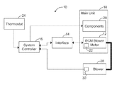
- FIG. 1 is a block diagram of an air moving control system including an electronically commutated motor (ECM) and a blower.
- ECM electronically commutated motor
- FIG. 2 is a flowchart illustration of a method for determining if the rotation of the ECM and blower at a predefined speed is in the desired direction of rotation.
- FIG. 3 is a flowchart illustration of a method for determining if the rotation of the ECM and blower at a selected level of torque is in the desired direction of rotation.
- FIG. 1 is a block diagram of an air moving control system 10 used to control an electronically commutated motor (ECM) 12 .
- System 10 is an air moving control system, such as a residential heating, ventilation and air conditioning (HVAC) control system, a light industrial HVAC control system, or a clean room filtering control system.
- System 10 includes an interface circuit 14 electrically coupled to a system controller 16 , for example a HVAC system controller, and a main unit 18 , for example a HVAC unit.
- Main unit 18 includes components 20 and ECM 12 .
- ECM 12 is a motor configured to rotate a blower.
- Motor 12 includes a motor controller 22 including a microprocessor (not shown) and a memory (not shown) containing an ECM program.
- system controller 16 is connected to a thermostat 24 .
- Thermostat 24 includes a plurality of settings, or modes, such as low heat, high heat, cooling, dehumidify, and continuous fan. Additionally, thermostat 24 measures a temperature in a predetermined space or location and transmits an electrical signal representing the measured temperature to controller 16 .
- Controller 16 controls main unit 18 via interface circuit 14 .
- Interface circuit 14 receives control signals in the form of input voltage signals from system controller 16 and translates the signals to signals suitable for controlling by ECM 12 .
- circuits within system 10 operate at a different voltage level than does ECM 12 . Therefore interface 14 is utilized for communications between controller 16 and ECM 12 .
- Such interfaces typically control ECMs using pulse width modulation (PWM) by continuously adjusting motor speed.
- PWM pulse width modulation
- blower 28 includes a detection module 30 which provides signals, for example signals indicative of a speed of rotation of blower 28 , to system controller 16 .
- blower 28 is a forward curved centrifugal blower.
- System 10 is configured to automatically determine a proper direction of rotation for ECM 12 .
- the proper direction of rotation for a blower is the direction of rotation that causes the desired airflow through, for example, the HVAC system. Once the correct direction of rotation is determined, it is stored within the memory of motor controller 22 such that ECM will rotate in the proper (desired) direction upon subsequent applications of power.
- a curvature of the blades of blower 28 is such that blower 28 produces useful work in one direction only.
- ECM 12 is attached to blower 28 .
- the load curve for a forward, or proper, direction of rotation is markedly different, than the load curve for reverse rotation. Specifically, a much higher torque, for a given rotation speed, must be applied to blower 28 for rotation in the proper direction. Once such a torque determination is made, the direction of rotation which resulted in the higher torque is stored within motor controller 22 .
- System 10 is configured to determine the proper direction of rotation for ECM 12 .
- system controller 16 and motor controller 22 are configured to cause ECM 12 to rotate at a set level of torque.
- Detection module 30 senses rotation, and a speed of rotation, of blower 28 .
- system controller 16 senses the speed of rotation of blower 28 , and determines if the measured speed is a speed consistent for the applied torque level. If so, then ECM 12 (and blower 28 ) are rotating in the proper direction and the direction of rotation is stored within motor controller 22 . If the resultant speed is too great, then it is determined that ECM 12 (and blower 28 ) are rotating in a direction opposite the desired direction, and the opposite direction of rotation is stored within motor controller 22 and is accessed during subsequent applications of power to ECM 12 .
- ECM 12 (and blower 28 ) are powered up to rotate at a selected speed.
- the speed can be measured utilizing either detection module 30 or motor controller 22 . If the torque required to reach such a rotation speed is less than expected, ECM 12 (and blower 28 ) are not rotating in the desired direction and motor controller 22 memory is updated accordingly to ensure that ECM 12 is rotated in the correct direction when power is subsequently applied.
- controller 22 is configured to rotate ECM 12 (and blower 28 ) a small amount in each direction, such as one or two revolutions.
- detection module 30 the deceleration rates of blower 28 are observed when current is removed from ECM 12 .
- the deceleration rates taken when passing through a given speed for each direction of rotation are compared, and the direction of rotation having the highest deceleration rate becomes the desired direction of rotation and is stored as such within the memory of motor controller 22 .
- either or both of speeds and applied torque in each direction can be compared to determine the desired direction of rotation. Once the comparison is made and determination of the desired direction of rotation is completed, data indicative of the desired direction of rotation is stored within the memory of motor controller 22 .
- the direction of rotation testing will be performed only on an initial power up of ECM 12 , since the desired direction of rotation is stored in memory (e.g., memory within system controller 16 or within the memory associated with motor controller 22 ) for all following start ups of ECM 12 . Since ECM 12 is intended to be continuously powered, the reoccurrence of the above described blower direction testing will be very infrequent.
- FIG. 2 is a flowchart 50 illustrating a method for determining if the rotation of the ECM (such as ECM 12 shown in FIG. 1 ) and the blower (such as blower 28 shown in FIG. 1 ) at a predefined speed is in the desired direction of rotation.
- the blower is rotated 52 with the ECM at a predefined speed.
- the torque required to maintain the predefined speed is then measured 54 . It is then determined 56 , for example within system controller 16 (shown in FIG. 1 ), whether the torque needed to maintain the predefined speed is indicative of the desired direction of rotation.
- the motor is rotating in a direction opposite the desired direction of rotation
- the data indicative of the desired direction of rotation for the motor is stored 58 within the motor controller.
- FIG. 3 is a flowchart 70 illustrating a method for determining if the rotation of the ECM (such as ECM 12 shown in FIG. 1 ) and blower (such as blower 28 shown in FIG. 1 ) at a selected level of torque is in the desired direction of rotation.
- the blower is rotated 72 with the ECM at a selected level of torque.
- the speed of the blower (or motor) is measured 74 . It is then determined 76 , for example within system controller 16 (shown in FIG. 1 ), whether the speed resulting from the selected level of torque is indicative of the desired direction of rotation.
- the motor is rotating in a direction opposite the desired direction of rotation.
- electronically commutated motors are typically used in air handling applications, for example, providing rotation to blowers and fans in HVAC systems.
- Known blower wheels and housings are found in both right hand and left hand configurations (clockwise and counter-clockwise rotation)
- a user is able to minimize the number of different motor models needed to serve both blower rotation directions as the motor control system is able to detect the proper rotation direction that for the blower it is to drive. Therefore, the automatic detection of rotation direction and storage within the motor controller of the desired direction of rotation for subsequent power ups features provide motor model inventory reduction. Also, the feature results in a reduction or elimination of instances where the wrong direction of rotation motor is installed with a blower, thereby reducing production line failures at an OEM.
Landscapes
- Engineering & Computer Science (AREA)
- Power Engineering (AREA)
- Control Of Positive-Displacement Air Blowers (AREA)
- Control Of Motors That Do Not Use Commutators (AREA)
- Control Of Electric Motors In General (AREA)
- Control Of Ac Motors In General (AREA)
Abstract
Description
Claims (20)
Priority Applications (5)
| Application Number | Priority Date | Filing Date | Title |
|---|---|---|---|
| US13/942,253 US8847526B2 (en) | 2005-05-31 | 2013-07-15 | Methods and systems for automatic rotation direction determination of electronically commutated motor |
| US14/467,932 US9634594B2 (en) | 2005-05-31 | 2014-08-25 | Methods and systems for automatic rotation direction determination of electronically commutated motor |
| US15/478,401 US10516355B2 (en) | 2005-05-31 | 2017-04-04 | Methods and systems for automatic rotation direction determination of electronically commutated motor |
| US16/710,509 US11611299B2 (en) | 2005-05-31 | 2019-12-11 | Methods and systems for automatic rotation direction determination of electronically commutated motor |
| US18/185,263 US20230223874A1 (en) | 2005-05-31 | 2023-03-16 | Methods and systems for automatic rotation direction determination of electronically commutated motor |
Applications Claiming Priority (4)
| Application Number | Priority Date | Filing Date | Title |
|---|---|---|---|
| US11/142,136 US7573217B2 (en) | 2005-05-31 | 2005-05-31 | Methods and systems for automatic rotation direction determination of electronically commutated motor |
| US12/499,731 US8111029B2 (en) | 2005-05-31 | 2009-07-08 | Methods and systems for automatic rotation direction determination of electronically commutated motor |
| US13/366,053 US8487562B2 (en) | 2005-05-31 | 2012-02-03 | Methods and systems for automatic rotation direction determination of electronically commutated motor |
| US13/942,253 US8847526B2 (en) | 2005-05-31 | 2013-07-15 | Methods and systems for automatic rotation direction determination of electronically commutated motor |
Related Parent Applications (1)
| Application Number | Title | Priority Date | Filing Date |
|---|---|---|---|
| US13/366,053 Continuation US8487562B2 (en) | 2005-05-31 | 2012-02-03 | Methods and systems for automatic rotation direction determination of electronically commutated motor |
Related Child Applications (1)
| Application Number | Title | Priority Date | Filing Date |
|---|---|---|---|
| US14/467,932 Continuation US9634594B2 (en) | 2005-05-31 | 2014-08-25 | Methods and systems for automatic rotation direction determination of electronically commutated motor |
Publications (2)
| Publication Number | Publication Date |
|---|---|
| US20130334994A1 US20130334994A1 (en) | 2013-12-19 |
| US8847526B2 true US8847526B2 (en) | 2014-09-30 |
Family
ID=37461640
Family Applications (8)
| Application Number | Title | Priority Date | Filing Date |
|---|---|---|---|
| US11/142,136 Active 2027-12-31 US7573217B2 (en) | 2005-05-31 | 2005-05-31 | Methods and systems for automatic rotation direction determination of electronically commutated motor |
| US12/499,731 Active US8111029B2 (en) | 2005-05-31 | 2009-07-08 | Methods and systems for automatic rotation direction determination of electronically commutated motor |
| US13/366,053 Active US8487562B2 (en) | 2005-05-31 | 2012-02-03 | Methods and systems for automatic rotation direction determination of electronically commutated motor |
| US13/942,253 Active US8847526B2 (en) | 2005-05-31 | 2013-07-15 | Methods and systems for automatic rotation direction determination of electronically commutated motor |
| US14/467,932 Active 2025-06-11 US9634594B2 (en) | 2005-05-31 | 2014-08-25 | Methods and systems for automatic rotation direction determination of electronically commutated motor |
| US15/478,401 Active US10516355B2 (en) | 2005-05-31 | 2017-04-04 | Methods and systems for automatic rotation direction determination of electronically commutated motor |
| US16/710,509 Active US11611299B2 (en) | 2005-05-31 | 2019-12-11 | Methods and systems for automatic rotation direction determination of electronically commutated motor |
| US18/185,263 Pending US20230223874A1 (en) | 2005-05-31 | 2023-03-16 | Methods and systems for automatic rotation direction determination of electronically commutated motor |
Family Applications Before (3)
| Application Number | Title | Priority Date | Filing Date |
|---|---|---|---|
| US11/142,136 Active 2027-12-31 US7573217B2 (en) | 2005-05-31 | 2005-05-31 | Methods and systems for automatic rotation direction determination of electronically commutated motor |
| US12/499,731 Active US8111029B2 (en) | 2005-05-31 | 2009-07-08 | Methods and systems for automatic rotation direction determination of electronically commutated motor |
| US13/366,053 Active US8487562B2 (en) | 2005-05-31 | 2012-02-03 | Methods and systems for automatic rotation direction determination of electronically commutated motor |
Family Applications After (4)
| Application Number | Title | Priority Date | Filing Date |
|---|---|---|---|
| US14/467,932 Active 2025-06-11 US9634594B2 (en) | 2005-05-31 | 2014-08-25 | Methods and systems for automatic rotation direction determination of electronically commutated motor |
| US15/478,401 Active US10516355B2 (en) | 2005-05-31 | 2017-04-04 | Methods and systems for automatic rotation direction determination of electronically commutated motor |
| US16/710,509 Active US11611299B2 (en) | 2005-05-31 | 2019-12-11 | Methods and systems for automatic rotation direction determination of electronically commutated motor |
| US18/185,263 Pending US20230223874A1 (en) | 2005-05-31 | 2023-03-16 | Methods and systems for automatic rotation direction determination of electronically commutated motor |
Country Status (1)
| Country | Link |
|---|---|
| US (8) | US7573217B2 (en) |
Cited By (1)
| Publication number | Priority date | Publication date | Assignee | Title |
|---|---|---|---|---|
| US20150092466A1 (en) * | 2013-09-27 | 2015-04-02 | Regal Beloit America, Inc. | System and method for converting a signal while maintaining electrical isolation |
Families Citing this family (21)
| Publication number | Priority date | Publication date | Assignee | Title |
|---|---|---|---|---|
| US7573217B2 (en) | 2005-05-31 | 2009-08-11 | Regal-Beloit Corporation | Methods and systems for automatic rotation direction determination of electronically commutated motor |
| US7567049B2 (en) * | 2006-04-21 | 2009-07-28 | Emerson Electric Co. | Fluid flow control for fluid handling systems |
| KR100946719B1 (en) * | 2007-11-28 | 2010-03-12 | 영 춘 정 | Apparatus to control a multi programmable constant air flow with speed controllable brushless motor |
| US20100256821A1 (en) * | 2009-04-01 | 2010-10-07 | Sntech Inc. | Constant airflow control of a ventilation system |
| US10012403B2 (en) * | 2009-05-21 | 2018-07-03 | Lennox Industries Inc. | Wiring connector housing |
| US8558493B2 (en) * | 2010-04-19 | 2013-10-15 | Nidec Motor Corporation | Blower motor for HVAC systems |
| US9071183B2 (en) | 2011-05-27 | 2015-06-30 | Regal Beloit America, Inc. | Methods and systems for providing combined blower motor and draft inducer motor control |
| EP2594802B1 (en) * | 2011-11-21 | 2016-04-20 | ABB Technology Oy | Method for detecting the correct rotational direction of a centrifugal apparatus, and a centrifugal apparatus assembly |
| CN103376743B (en) * | 2012-04-26 | 2016-06-22 | 中山大洋电机股份有限公司 | A kind of constant air capacity control of motor and air conditioner draught fan system |
| CN202833210U (en) * | 2012-06-30 | 2013-03-27 | 中山大洋电机股份有限公司 | Inducted draft fan driven by direct current motor |
| DE102012017963A1 (en) * | 2012-09-12 | 2014-03-13 | Andreas Stihl Ag & Co. Kg | Hand-operated implement with a drive circuit for an oscillating tools driving electric motor |
| US9337707B2 (en) * | 2013-01-28 | 2016-05-10 | Randy J. Dixon | System, apparatus, and method for controlling a motor |
| JP6058460B2 (en) * | 2013-04-23 | 2017-01-11 | 日立オートモティブシステムズ株式会社 | Brushless motor control device |
| US9806626B2 (en) | 2014-05-06 | 2017-10-31 | Regal Beloit America, Inc. | Electric motor controller and methods of determining input power line energization |
| US10295236B2 (en) * | 2014-08-13 | 2019-05-21 | Trane International Inc. | Compressor heating system |
| CN106523399B (en) * | 2015-09-15 | 2020-12-25 | 雷勃美国公司 | System and method for determining a condition of a fluid flow path |
| IT201800007037A1 (en) * | 2018-07-09 | 2020-01-09 | ROOM AIR CONDITIONING DEVICE AND METHOD FOR THE CONTROL OF A ROOM AIR CONDITIONING DEVICE. | |
| US10731889B2 (en) | 2019-01-08 | 2020-08-04 | Regal Beloit America, Inc. | Motor controller for electric blowers |
| US11841022B2 (en) * | 2020-01-06 | 2023-12-12 | Regal Beloit America, Inc. | Control system for electric fluid moving apparatus |
| WO2021223348A1 (en) * | 2020-05-08 | 2021-11-11 | 中山大洋电机股份有限公司 | Ecm motor compatible with multiple universal interfaces, heating, ventilation, and air conditioning (hvac) system, and signal conversion method |
| IT202100023915A1 (en) * | 2021-09-17 | 2023-03-17 | Askoll Holding S R L A Socio Unico | Method for controlling the direction of rotation of a fluid machine and processing unit configured to implement said method |
Citations (28)
| Publication number | Priority date | Publication date | Assignee | Title |
|---|---|---|---|---|
| US4390826A (en) | 1974-06-24 | 1983-06-28 | General Electric Company | Laundering apparatus, method of operating a laundry machine, control system for an electronically commutated motor, method of operating an electronically commutated motor, and circuit |
| US4636936A (en) | 1984-04-19 | 1987-01-13 | General Electric Company | Control system for an electronically commutated motor |
| US4638233A (en) | 1985-10-24 | 1987-01-20 | General Electric Company | Method of establishing a preferred rate of air flow, method of determining torque, and apparatus |
| US5198733A (en) | 1989-03-15 | 1993-03-30 | International Business Machines Corporation | Starting a brushless DC motor |
| US5376866A (en) | 1974-06-24 | 1994-12-27 | General Electric Company | Motor controls, refrigeration systems and methods of motor operation and control |
| US5410230A (en) | 1992-05-27 | 1995-04-25 | General Electric Company | Variable speed HVAC without controller and responsive to a conventional thermostat |
| US5418438A (en) | 1993-02-26 | 1995-05-23 | General Electric Company | Draft inducer air flow control |
| US5423192A (en) | 1993-08-18 | 1995-06-13 | General Electric Company | Electronically commutated motor for driving a compressor |
| US5492273A (en) | 1992-05-27 | 1996-02-20 | General Electric Company | Heating ventilating and/or air conditioning system having a variable speed indoor blower motor |
| US5818194A (en) | 1996-04-01 | 1998-10-06 | Emerson Electric Co. | Direct replacement variable speed blower motor |
| US5818183A (en) | 1994-12-06 | 1998-10-06 | Auto-Tilt Enterprises, Ltd. | Blind tilt controller |
| US5838127A (en) | 1996-12-05 | 1998-11-17 | General Electric Company | Single phase motor for laundering apparatus |
| US5986419A (en) * | 1996-07-15 | 1999-11-16 | General Electric Company | Quadrature axis winding for sensorless rotor angular position control of single phase permanent magnet motor |
| US6078152A (en) | 1996-01-10 | 2000-06-20 | Papst-Motoren Gmbh & Co. Kg | Bidirectional E.C. motor and method of operating the motor |
| US6215261B1 (en) | 1999-05-21 | 2001-04-10 | General Electric Company | Application specific integrated circuit for controlling power devices for commutating a motor based on the back emf of motor |
| US6396226B2 (en) | 1999-12-01 | 2002-05-28 | Papst Motoren Gmbh & Co. Kg | Electronically commutated DC motor |
| US6429615B2 (en) | 1999-12-08 | 2002-08-06 | Papst Motoren Gmbh & Co. Kg | Electronically commutated DC motor |
| US20020117986A1 (en) | 2001-02-27 | 2002-08-29 | Becerra Roger C. | Digital communication link |
| US6452349B1 (en) | 1998-11-09 | 2002-09-17 | Papst-Motoren Gmbh & Co. Kg | Electronically commutated motor |
| US6456023B1 (en) | 2001-08-08 | 2002-09-24 | General Electric Company | Method and apparatus to control a variable speed motor |
| US6456024B1 (en) | 1999-11-27 | 2002-09-24 | Papst-Motoren Gmbh & Co. Kg | Electronically commutated DC motor |
| US20030021692A1 (en) | 2001-07-30 | 2003-01-30 | Adams Jon R. | Method and apparatus for correcting motor imbalance |
| US20040112096A1 (en) | 2002-12-17 | 2004-06-17 | General Electric Company | Method and apparatus for electronically commutated motor washer agitation controller |
| US6825627B2 (en) | 2000-12-28 | 2004-11-30 | Ebm-Papst St. Georgen Gmbh & Co. Kg | Method for controlling the commutation of an electronically commutated motor |
| US6903526B2 (en) | 2002-04-11 | 2005-06-07 | Ebm-Papst St. Georgen Gmbh & Co. | Electronically commutated DC motor comprising a bridge circuit |
| US7573217B2 (en) | 2005-05-31 | 2009-08-11 | Regal-Beloit Corporation | Methods and systems for automatic rotation direction determination of electronically commutated motor |
| US7990092B2 (en) | 2008-09-08 | 2011-08-02 | Nidec Motor Corporation | Blower motor for HVAC systems |
| US8049459B2 (en) | 2008-09-08 | 2011-11-01 | Nidec Motor Corporation | Blower motor for HVAC systems |
Family Cites Families (27)
| Publication number | Priority date | Publication date | Assignee | Title |
|---|---|---|---|---|
| US21692A (en) * | 1858-10-05 | Roll fob making sheet-iron | ||
| US117986A (en) * | 1871-08-15 | Improvement in brooms | ||
| US645349A (en) * | 1899-03-06 | 1900-03-13 | Joseph Conley | Refuse-burner or crematory for burning garbage. |
| US4250544A (en) * | 1980-01-04 | 1981-02-10 | General Electric Company | Combination microprocessor and discrete element control system for a clock rate controlled electronically commutated motor |
| US4455513A (en) * | 1982-07-26 | 1984-06-19 | Imec Corporation | Self-starting transducerless, brushless D.C. motor controller |
| US4500821A (en) * | 1983-06-09 | 1985-02-19 | General Electric Company | Speed or torque control circuit for an electronically commutated motor (ECM) and method of controlling the torque or speed of an ECM |
| US4642537A (en) * | 1983-12-13 | 1987-02-10 | General Electric Company | Laundering apparatus |
| US4540921A (en) * | 1984-04-19 | 1985-09-10 | General Electric Company | Laundry apparatus and method of controlling such |
| NZ213490A (en) * | 1985-09-16 | 1990-03-27 | Fisher & Paykel | Cyclic motor reversal by forced commutation |
| US4757603A (en) * | 1986-05-23 | 1988-07-19 | General Electric Company | Method of making a reinforced rotor assembly |
| US4757241A (en) * | 1987-10-19 | 1988-07-12 | General Electric Company | PWM system for ECM motor |
| US5017845A (en) * | 1990-10-05 | 1991-05-21 | Sgs-Thomson Microelectronics, Inc. | Brushless direct current motor starting and operating apparatus and method |
| US5258695A (en) * | 1990-12-19 | 1993-11-02 | Integral Peripherals, Inc. | Spin motor control system for a hard disk assembly |
| US5298838A (en) * | 1991-02-21 | 1994-03-29 | Silicon Systems, Inc. | Sensorless brushless DC motor starting system and method |
| IT1253596B (en) * | 1991-10-31 | 1995-08-22 | Sgs Thomson Microelectronics | STARTING SYSTEM FOR A MULTI-PHASE BRUSHLESS MOTOR, WITHOUT ROTOR POSITION SENSORS. |
| JPH07226016A (en) * | 1994-02-14 | 1995-08-22 | Fujitsu Ltd | Method for controlling start of motor of disk device |
| US5524556A (en) * | 1995-06-09 | 1996-06-11 | Texas Instruments Incorporated | Induced draft fan control for use with gas furnaces |
| US5744921A (en) * | 1996-05-02 | 1998-04-28 | Siemens Electric Limited | Control circuit for five-phase brushless DC motor |
| US5825597A (en) * | 1996-09-25 | 1998-10-20 | General Electric Company | System and method for detection and control of circulating currents in a motor |
| US6104113A (en) * | 1998-05-14 | 2000-08-15 | General Electric Company | Coil assembly for sensorless rotor angular position control of single phase permanent magnet motor |
| US6118239A (en) * | 1998-11-23 | 2000-09-12 | Kadah; Andrew S. | Speed control drive circuit for blower motor |
| US6100656A (en) * | 1999-01-19 | 2000-08-08 | Quantum Corporation | Start-up algorithm for a brushless sensorless motor |
| US20010048278A1 (en) * | 1999-02-04 | 2001-12-06 | Glen C. Young | Cross coupled motor gate drive |
| DE59909585D1 (en) * | 1999-03-23 | 2004-07-01 | Ebm Papst Mulfingen Gmbh & Co | Blower with a predetermined characteristic |
| US6356044B1 (en) * | 1999-12-03 | 2002-03-12 | General Electric Company | Motor with programming module |
| US6600979B1 (en) * | 2002-02-26 | 2003-07-29 | General Electric Company | Method and system for determining an inertially-adjusted vehicle reference speed |
| US7514887B2 (en) * | 2003-10-24 | 2009-04-07 | A. O. Smith Corporation | Electrical machine and method of controlling the same |
-
2005
- 2005-05-31 US US11/142,136 patent/US7573217B2/en active Active
-
2009
- 2009-07-08 US US12/499,731 patent/US8111029B2/en active Active
-
2012
- 2012-02-03 US US13/366,053 patent/US8487562B2/en active Active
-
2013
- 2013-07-15 US US13/942,253 patent/US8847526B2/en active Active
-
2014
- 2014-08-25 US US14/467,932 patent/US9634594B2/en active Active
-
2017
- 2017-04-04 US US15/478,401 patent/US10516355B2/en active Active
-
2019
- 2019-12-11 US US16/710,509 patent/US11611299B2/en active Active
-
2023
- 2023-03-16 US US18/185,263 patent/US20230223874A1/en active Pending
Patent Citations (30)
| Publication number | Priority date | Publication date | Assignee | Title |
|---|---|---|---|---|
| US5376866A (en) | 1974-06-24 | 1994-12-27 | General Electric Company | Motor controls, refrigeration systems and methods of motor operation and control |
| US4390826A (en) | 1974-06-24 | 1983-06-28 | General Electric Company | Laundering apparatus, method of operating a laundry machine, control system for an electronically commutated motor, method of operating an electronically commutated motor, and circuit |
| US4636936A (en) | 1984-04-19 | 1987-01-13 | General Electric Company | Control system for an electronically commutated motor |
| US4638233A (en) | 1985-10-24 | 1987-01-20 | General Electric Company | Method of establishing a preferred rate of air flow, method of determining torque, and apparatus |
| US5198733A (en) | 1989-03-15 | 1993-03-30 | International Business Machines Corporation | Starting a brushless DC motor |
| US5410230A (en) | 1992-05-27 | 1995-04-25 | General Electric Company | Variable speed HVAC without controller and responsive to a conventional thermostat |
| US5492273A (en) | 1992-05-27 | 1996-02-20 | General Electric Company | Heating ventilating and/or air conditioning system having a variable speed indoor blower motor |
| US5592058A (en) | 1992-05-27 | 1997-01-07 | General Electric Company | Control system and methods for a multiparameter electronically commutated motor |
| US5418438A (en) | 1993-02-26 | 1995-05-23 | General Electric Company | Draft inducer air flow control |
| US5423192A (en) | 1993-08-18 | 1995-06-13 | General Electric Company | Electronically commutated motor for driving a compressor |
| US5818183A (en) | 1994-12-06 | 1998-10-06 | Auto-Tilt Enterprises, Ltd. | Blind tilt controller |
| US6078152A (en) | 1996-01-10 | 2000-06-20 | Papst-Motoren Gmbh & Co. Kg | Bidirectional E.C. motor and method of operating the motor |
| US5818194A (en) | 1996-04-01 | 1998-10-06 | Emerson Electric Co. | Direct replacement variable speed blower motor |
| US5986419A (en) * | 1996-07-15 | 1999-11-16 | General Electric Company | Quadrature axis winding for sensorless rotor angular position control of single phase permanent magnet motor |
| US5838127A (en) | 1996-12-05 | 1998-11-17 | General Electric Company | Single phase motor for laundering apparatus |
| US6452349B1 (en) | 1998-11-09 | 2002-09-17 | Papst-Motoren Gmbh & Co. Kg | Electronically commutated motor |
| US6215261B1 (en) | 1999-05-21 | 2001-04-10 | General Electric Company | Application specific integrated circuit for controlling power devices for commutating a motor based on the back emf of motor |
| US6456024B1 (en) | 1999-11-27 | 2002-09-24 | Papst-Motoren Gmbh & Co. Kg | Electronically commutated DC motor |
| US6396226B2 (en) | 1999-12-01 | 2002-05-28 | Papst Motoren Gmbh & Co. Kg | Electronically commutated DC motor |
| US6429615B2 (en) | 1999-12-08 | 2002-08-06 | Papst Motoren Gmbh & Co. Kg | Electronically commutated DC motor |
| US6825627B2 (en) | 2000-12-28 | 2004-11-30 | Ebm-Papst St. Georgen Gmbh & Co. Kg | Method for controlling the commutation of an electronically commutated motor |
| US20020117986A1 (en) | 2001-02-27 | 2002-08-29 | Becerra Roger C. | Digital communication link |
| US20030021692A1 (en) | 2001-07-30 | 2003-01-30 | Adams Jon R. | Method and apparatus for correcting motor imbalance |
| US6456023B1 (en) | 2001-08-08 | 2002-09-24 | General Electric Company | Method and apparatus to control a variable speed motor |
| US6903526B2 (en) | 2002-04-11 | 2005-06-07 | Ebm-Papst St. Georgen Gmbh & Co. | Electronically commutated DC motor comprising a bridge circuit |
| US20040112096A1 (en) | 2002-12-17 | 2004-06-17 | General Electric Company | Method and apparatus for electronically commutated motor washer agitation controller |
| US7573217B2 (en) | 2005-05-31 | 2009-08-11 | Regal-Beloit Corporation | Methods and systems for automatic rotation direction determination of electronically commutated motor |
| US8111029B2 (en) | 2005-05-31 | 2012-02-07 | Rbc Manufacturing Corporation | Methods and systems for automatic rotation direction determination of electronically commutated motor |
| US7990092B2 (en) | 2008-09-08 | 2011-08-02 | Nidec Motor Corporation | Blower motor for HVAC systems |
| US8049459B2 (en) | 2008-09-08 | 2011-11-01 | Nidec Motor Corporation | Blower motor for HVAC systems |
Cited By (2)
| Publication number | Priority date | Publication date | Assignee | Title |
|---|---|---|---|---|
| US20150092466A1 (en) * | 2013-09-27 | 2015-04-02 | Regal Beloit America, Inc. | System and method for converting a signal while maintaining electrical isolation |
| US9379635B2 (en) * | 2013-09-27 | 2016-06-28 | Regal Beloit America, Inc. | System and method for converting a signal while maintaining electrical isolation |
Also Published As
| Publication number | Publication date |
|---|---|
| US9634594B2 (en) | 2017-04-25 |
| US20130334994A1 (en) | 2013-12-19 |
| US20090274563A1 (en) | 2009-11-05 |
| US20170207737A1 (en) | 2017-07-20 |
| US10516355B2 (en) | 2019-12-24 |
| US11611299B2 (en) | 2023-03-21 |
| US20200119669A1 (en) | 2020-04-16 |
| US7573217B2 (en) | 2009-08-11 |
| US20230223874A1 (en) | 2023-07-13 |
| US20140361716A1 (en) | 2014-12-11 |
| US20120133312A1 (en) | 2012-05-31 |
| US20060265890A1 (en) | 2006-11-30 |
| US8487562B2 (en) | 2013-07-16 |
| US8111029B2 (en) | 2012-02-07 |
Similar Documents
| Publication | Publication Date | Title |
|---|---|---|
| US11611299B2 (en) | Methods and systems for automatic rotation direction determination of electronically commutated motor | |
| CA2421565C (en) | Methods and systems for controlling air filtration systems | |
| MX2014003092A (en) | Method for correcting torque for substituting permament-split capacitor motor by electronically-commutated motor. | |
| JP2013518554A (en) | Speed limited torque control | |
| US20210372884A1 (en) | Determination of pulley ratio of a belt-drive blower | |
| CN117271272B (en) | BMC-based fan in-place state monitoring method and system | |
| US5572876A (en) | Operational control method and apparatus for an air conditioner | |
| KR20090069995A (en) | Method for driving silentness of air conditionner by controllng speed of fan moter for indoor unit | |
| EP3415831B1 (en) | Cooling fan automatic control system and cooling fan automatic control device | |
| EP4120550A1 (en) | Two degrees of control through pulse width modulation interface | |
| KR20180007202A (en) | Apparatus for controlling fan motor of a duct type air conditioner and operating method of thereof | |
| KR20100133094A (en) | Constant airflow control of a ventilation system | |
| CN113720091A (en) | Method and device for controlling rotating speed of compressor of vehicle-mounted refrigerator and vehicle-mounted refrigerator | |
| CN112253519B (en) | Fan control circuit, method, controller and electric equipment | |
| US20230020014A1 (en) | Current monitor air filter replacement | |
| EP4123237A1 (en) | Electronically commutated motor zero-watt standby power consumption | |
| GB2432015A (en) | A method for comissioning a fan | |
| KR20230112987A (en) | Apparatus for controlling fan motor, air conditioning system and constant airflow control method of apparatus for controlling fan motor | |
| JP3314799B2 (en) | Method and apparatus for controlling air conditioner | |
| JP2002340451A (en) | Outdoor unit of air conditioner | |
| JPH0223408A (en) | Rotation control system for cooling fan | |
| JPH08168287A (en) | Method for controlling motor | |
| KR19990054087A (en) | Operation controller and method of air conditioner | |
| JP2004061036A (en) | Air conditioner | |
| JP2004185236A (en) | Equipment controller and blowing device |
Legal Events
| Date | Code | Title | Description |
|---|---|---|---|
| AS | Assignment |
Owner name: REGAL-BELOIT CORPORATION, WISCONSIN Free format text: ASSIGNMENT OF ASSIGNORS INTEREST;ASSIGNORS:SOLAN, STEPHEN, JR.;BEIFUS, BRIAN L.;BECERRA, ROGER C.;SIGNING DATES FROM 20050902 TO 20050913;REEL/FRAME:031219/0846 Owner name: REGAL BELOIT AMERICA, INC., WISCONSIN Free format text: ASSIGNMENT OF ASSIGNORS INTEREST;ASSIGNOR:RBC MANUFACTURING CORPORATION;REEL/FRAME:031220/0107 Effective date: 20121231 Owner name: RBC MANUFACTURING CORPORATION, WISCONSIN Free format text: ASSIGNMENT OF ASSIGNORS INTEREST;ASSIGNOR:REGAL-BELOIT CORPORATION;REEL/FRAME:031219/0922 Effective date: 20111019 |
|
| FEPP | Fee payment procedure |
Free format text: PAYOR NUMBER ASSIGNED (ORIGINAL EVENT CODE: ASPN); ENTITY STATUS OF PATENT OWNER: LARGE ENTITY |
|
| STCF | Information on status: patent grant |
Free format text: PATENTED CASE |
|
| MAFP | Maintenance fee payment |
Free format text: PAYMENT OF MAINTENANCE FEE, 4TH YEAR, LARGE ENTITY (ORIGINAL EVENT CODE: M1551) Year of fee payment: 4 |
|
| MAFP | Maintenance fee payment |
Free format text: PAYMENT OF MAINTENANCE FEE, 8TH YEAR, LARGE ENTITY (ORIGINAL EVENT CODE: M1552); ENTITY STATUS OF PATENT OWNER: LARGE ENTITY Year of fee payment: 8 |