US8840083B2 - Intake valve for a cylinder of the high-pressure fuel pump of a common rail injection system - Google Patents
Intake valve for a cylinder of the high-pressure fuel pump of a common rail injection system Download PDFInfo
- Publication number
- US8840083B2 US8840083B2 US13/119,991 US200913119991A US8840083B2 US 8840083 B2 US8840083 B2 US 8840083B2 US 200913119991 A US200913119991 A US 200913119991A US 8840083 B2 US8840083 B2 US 8840083B2
- Authority
- US
- United States
- Prior art keywords
- closing body
- inlet opening
- cylindrical
- intake valve
- cylindrical projection
- Prior art date
- Legal status (The legal status is an assumption and is not a legal conclusion. Google has not performed a legal analysis and makes no representation as to the accuracy of the status listed.)
- Expired - Fee Related, expires
Links
Images


Classifications
-
- F—MECHANICAL ENGINEERING; LIGHTING; HEATING; WEAPONS; BLASTING
- F04—POSITIVE - DISPLACEMENT MACHINES FOR LIQUIDS; PUMPS FOR LIQUIDS OR ELASTIC FLUIDS
- F04B—POSITIVE-DISPLACEMENT MACHINES FOR LIQUIDS; PUMPS
- F04B1/00—Multi-cylinder machines or pumps characterised by number or arrangement of cylinders
- F04B1/04—Multi-cylinder machines or pumps characterised by number or arrangement of cylinders having cylinders in star- or fan-arrangement
- F04B1/0404—Details or component parts
- F04B1/0426—Arrangements for pressing the pistons against the actuated cam; Arrangements for connecting the pistons to the actuated cam
-
- F—MECHANICAL ENGINEERING; LIGHTING; HEATING; WEAPONS; BLASTING
- F02—COMBUSTION ENGINES; HOT-GAS OR COMBUSTION-PRODUCT ENGINE PLANTS
- F02M—SUPPLYING COMBUSTION ENGINES IN GENERAL WITH COMBUSTIBLE MIXTURES OR CONSTITUENTS THEREOF
- F02M59/00—Pumps specially adapted for fuel-injection and not provided for in groups F02M39/00 -F02M57/00, e.g. rotary cylinder-block type of pumps
- F02M59/44—Details, components parts, or accessories not provided for in, or of interest apart from, the apparatus of groups F02M59/02 - F02M59/42; Pumps having transducers, e.g. to measure displacement of pump rack or piston
- F02M59/46—Valves
- F02M59/464—Inlet valves of the check valve type
Definitions
- the invention relates to an intake valve for a cylinder of the high-pressure fuel pump of a common rail injection system.
- Diesel motor vehicles which contain a common rail injection system are already known.
- the rail pressure is one of the main parameters which influence the fuel injection quantity. For this reason, the presence of as stable a rail pressure as possible is an essential precondition for accurate metering of the fuel injection quantity.
- the rail pressure is dependent on the cylinder filling of the high-pressure fuel pump.
- Non-uniform filling of the cylinders in a two cylinder pump or a three cylinder pump leads to pressure fluctuations in the rail.
- Non-uniform filling of this type of the cylinders can be ascribed, inter alia, to different volumetric flow characteristics of the inlet valves of the cylinders.
- the different volumetric flow characteristics of the inlet valves are caused, in particular, by different opening pressures of the inlet valves of the cylinders, which inlet valves are realized as an intake valve.
- the different opening pressures are to be ascribed, for example, to production-related different spring prestresses of the inlet valves and/or to undefined contact lines between the closing body and the valve seat of the inlet valves. Furthermore, the stated contact line of an inlet valve can change in the first operating hours of the inlet valve as a result of a deformation of the valve seat in an undesired manner.
- FIG. 1 shows one example for the dependence of the cylinder filling on the opening pressure of the inlet valve.
- the pressure difference dP in bar is shown along the ordinate and the fuel inlet quantity Q in liters per minute is shown along the abscissa.
- the curve K 1 describes an inlet operation, in which the opening pressure corresponds to a pressure difference dP of 1.2 bar
- the curve K 2 describes an inlet operation, in which the opening pressure corresponds to a pressure difference dP of 1.4 bar.
- the inlet quantity at an opening pressure of the inlet valve of 1.2 bar is greater by ⁇ Q ⁇ 0.1 l/min than the inlet quantity at an opening pressure of the inlet valve of 1.4 bar.
- the volumetric flow characteristic of conventional inlet valves is linear, that is to say the change in the inlet quantity proceeds linearly with respect to a change in the pressure difference dP.
- FIG. 2 shows a diagram, in which the delivery volume of the cylinders is shown as a function of time.
- the conveying volume in liters is plotted along the ordinate and the time in seconds is plotted along the abscissa.
- the curve K 3 with the continuous lines is assigned to a cylinder, the inlet valve of which has an opening pressure of 1.4 bar
- the curve K 4 with the dashed lines is assigned to a cylinder, the inlet valve of which has an opening pressure of 1.2 bar. It can be seen that the delivery volume of both cylinders deviates by ⁇ Q ⁇ 0.02 liter per inlet operation.
- the opening pressure of an inlet valve lies in the range between 1.2 and 1.7 bar. At an opening pressure which is lower than 1.2 bar, the risk increases that an air/liquid mixture is sucked through the intake valve into the compression chamber. As a result of the entrained, compressible air, no complete filling is achieved and the pressure pulses in the rail increase.
- inlet valves of this type In the context of the production of inlet valves of this type, said inlet valves are measured and divided into different classes. In practice, production failures of up to 50% occur with the current design.
- an inlet valve for a cylinder of the high-pressure fuel pump of a common rail injection system can be specified, in which the above-described disadvantages are reduced.
- an intake valve for a cylinder of the high-pressure fuel pump of a common rail injection system may have a valve body, which has an inlet opening, and a closing body which can be moved relative to the inlet opening and closes the inlet opening in a first end position, characterized in that the volumetric flow characteristic of the intake valve is non-linear.
- the contour of the closing body and/or the contour of the valve body can be designed in such a way that the volumetric flow characteristic is non-linear.
- the closing body on its side which faces the inlet opening, may have a step and/or a bevel. According to a further embodiment, on its side which faces the inlet opening, the closing body may have a right-angled transition. According to a further embodiment, the intake valve's opening area can be in a non-linear relationship with a pressure difference. According to a further embodiment, the inlet opening can be a hollow-cylindrical inlet channel. According to a further embodiment, the closing body may have a cylindrical projection which protrudes into the inlet channel. According to a further embodiment, the closing body may have a cylindrical collar, the diameter of which is greater than the diameter of the cylindrical projection, and in that the transition point between the cylindrical projection and the collar is of right-angled configuration.
- FIG. 1 shows one example for the dependence of the cylinder filling on the opening pressure of the inlet valve
- FIG. 2 shows a diagram, in which the delivery volume of the cylinders is shown as a function of time
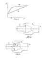
- FIG. 3 shows a diagram for illustrating the dependence of the cylinder filling on the slope of the volumetric flow characteristic curve
- FIG. 4 shows a diagram for illustrating a linear and a non-linear volumetric flow characteristic of an intake valve
- FIG. 5 shows a diagram of an intake valve with a linear volumetric flow characteristic
- FIG. 6 shows a diagram of a first exemplary embodiment of an intake valve with a non-linear volumetric flow characteristic
- FIGS. 7 a and 7 b show enlarged details of the intake valve according to FIG. 6 in different opening positions of the closing body
- FIG. 8 shows a diagram of a second exemplary embodiment of an intake valve with a non-linear volumetric flow characteristic.
- an intake valve may have an inlet opening and a closing body, the closing body closing the inlet opening in a first end position and being movable relative to the inlet opening as a function of a pressure difference, and the intake valve having a non-linear volumetric flow characteristic.
- said non-linear volumetric flow characteristic can be achieved by a corresponding design of the contour of the closing body of the intake valve.
- the closing body On its side which faces the inlet opening, the closing body preferably has a bevel and/or a step. This advantageously achieves a situation where the opening area of the inlet valve is in a non-linear relationship with the pressure difference.
- the inlet opening is preferably a hollow-cylindrical inlet channel and the closing body is preferably a cylindrical projection which protrudes into the inlet channel.
- this accuracy can be increased further by the fact that the closing body has a cylindrical collar, the diameter of which is greater than the diameter of the cylindrical projection, the transition points between the cylindrical projection and the collar being of right-angled configuration.
- an intake valve for a cylinder of the high-pressure fuel pump of a common rail injection system has an inlet opening, through which fuel which is conveyed into a fuel annular channel passes into the valve body from a tank by means of a prefeed pump. From said valve body, the fuel is transported via an outlet opening of the intake valve into an associated cylinder of the high-pressure fuel pump. This is followed by closure of the inlet valve, compression of the fuel which is situated in the cylinder by means of a piston which is moved in the cylinder, and discharging of the compressed fuel via a rail line into the rail.
- an intake valve has a closing body which is connected to a spring and, in a first end position, closes the inlet opening of the intake valve when the spring is relieved.
- the closing body can be moved relative to the inlet opening as a function of the pressure difference which exists between the pressure existing in the fuel annular channel and the sum of the pressure in the cylinder and the pressure caused by the closing force of the spring, in order to open or to close the intake valve. If the pressure of the fuel in the fuel annular channel becomes higher than the sum of the pressure in the cylinder and the pressure caused by the closing force of the spring, the inlet valve is opened. If the pressure of the fuel in the fuel annular channel is lower than the sum of the pressure in the cylinder and the pressure caused by the closing force of the spring, the inlet valve is closed.
- An intake valve has a non-linear volumetric flow characteristic, as will be explained in the following text.
- the curve K 1 describes an inlet operation, in which the opening pressure corresponds to a pressure difference dP of 1.2 bar
- the curve K 2 describes an inlet operation, in which the opening pressure corresponds to a pressure difference dP of 1.4 bar
- the curve K 3 describes an inlet operation, in which the opening pressure likewise corresponds to a pressure difference of 1.2 bar
- the curve K 4 describes an inlet operation, in which the opening pressure corresponds to a pressure difference dP of 1.4 bar.
- the curves K 1 and K 2 have a greater slope than the curves K 3 and K 4 .
- a steep volumetric flow characteristic which can be realized, for example, using a spring with a relatively great rigidity causes relatively large pressure losses, however, and is not acceptable for a full fuel delivery.
- a non-linear volumetric flow characteristic of the inlet valves achieves a situation where the inlet quantity deviations of the inlet valves of a high-pressure fuel pump are reduced in comparison with the prior art.
- FIG. 4 This is illustrated using FIG. 4 , in which the pressure difference dP is plotted along the ordinate and the inlet quantity Q is plotted along the abscissa.
- the curve K 5 describes a linear volumetric flow characteristic
- the curve K 6 describes a non-linear volumetric flow characteristic.
- the curve K 6 has a substantially steeper course than the curve K 5 and, in the case of fuel inlet quantities which are greater than QG, has a flatter course than the curve K 5 .
- the opening area A of a conventional inlet valve is a linear function of the pressure difference.
- the desired non-linearity is achieved by a combination of the Bernoulli flow and the gap flow. This will be explained in greater detail in the following text using FIGS. 5-8 .
- FIG. 5 shows a diagram of an intake valve with a linear volumetric flow characteristic.
- the intake valve which is shown has a valve body 1 which contains a hollow-cylindrical inlet opening 1 a and an outlet opening 1 b .
- the intake valve which is shown has a closing body 2 .
- the closing body 2 is connected to a spring (not illustrated) and closes the inlet opening 1 a in the relieved state of said spring, with the result that no fuel can pass out of the fuel annular channel into the interior of the valve body 1 and from there via the outlet opening 1 b into the associated cylinder of the high-pressure fuel pump.
- the closing body 2 is configured to be flat in the direction of the inlet opening 1 a .
- FIG. 6 shows a diagram of a first exemplary embodiment of an intake valve with a non-linear volumetric flow characteristic.
- This intake valve also has a valve body 1 which contains a hollow-cylindrical inlet opening 1 a and an outlet opening 1 b .
- the intake valve shown in FIG. 6 also has a closing body 2 .
- This closing body is also connected to a spring (not illustrated) and closes the inlet opening 1 a in the relieved state of said spring, with the result that no fuel can pass out of the fuel annular channel into the interior of the valve body 1 and from there via the outlet opening 1 b into the interior of the associated cylinder of the high-pressure fuel pump.
- the closing body which is shown in FIG.
- the closing body 2 is not configured to be flat in the direction of the inlet opening 1 a , but rather has a circumferential step 2 a and a circumferential bevel 2 b on its side which faces the inlet opening 1 a .
- the intake valve shown in FIG. 6 has a non-linear volumetric flow characteristic.
- FIGS. 7 a and 7 b said figures showing enlarged details of the intake valve according to FIG. 6 in different open positions of the closing body 2 .
- the closing body 2 is shown in FIG. 7 a in a partially open state which corresponds to a stroke of 20 ⁇ m, and is shown in FIG. 7 b in a more open state which corresponds to a stroke of 100 ⁇ m.
- the opening area of the valve has a non-linear relationship with the pressure or the pressure difference.
- FIG. 8 shows a diagram of a second exemplary embodiment of an intake valve with a non-linear volumetric flow characteristic.
- This intake valve also has a valve body 1 which contains a hollow-cylindrical inlet opening 1 a and an outlet opening 1 b .
- the intake valve shown in FIG. 8 also has a closing body 2 which is connected to a spring (not illustrated) and closes the inlet opening 1 a in the relieved state of said spring, with the result that no fuel can pass out of the fuel annular channel into the interior of the associated cylinder of the high-pressure fuel pump.
- the closing body 2 has, on its side which faces the inlet opening 1 a , a right-angled transition 2 c which is provided between a cylindrical collar 2 d of the closing body 2 and a cylindrical projection 2 e of the closing body 2 , which cylindrical projection 2 e protrudes into the hollow-cylindrical inlet opening 1 a .
- the length of the cylindrical projection 2 e of the closing body 2 is denoted by the letter L.
- the diameter DK of the cylindrical collar 2 d is greater than the diameter DE of the hollow-cylindrical inlet opening 1 a and is also greater than the diameter DF of the cylindrical projection of the closing body 2 .
- DF is the diameter of the cylindrical projection of the closing body
- DE is the diameter of the hollow-cylindrical inlet opening
- ⁇ is the difference between the previously mentioned two diameters.
- a non-linear volumetric flow characteristic can also be realized by intake valves, in which the valve body and the closing body are in each case of conical configuration in their contact region, the flanks not extending parallel to one another.
- a further alternative embodiment consists of realizing a non-linear volumetric flow characteristic by way of an intake valve, in which there is a ball/cone transition in the contact region between the valve body and the closing body.
Landscapes
- Engineering & Computer Science (AREA)
- Mechanical Engineering (AREA)
- General Engineering & Computer Science (AREA)
- Chemical & Material Sciences (AREA)
- Combustion & Propulsion (AREA)
- Fuel-Injection Apparatus (AREA)
Applications Claiming Priority (4)
| Application Number | Priority Date | Filing Date | Title |
|---|---|---|---|
| DE102008048450.4 | 2008-09-23 | ||
| DE200810048450 DE102008048450B4 (de) | 2008-09-23 | 2008-09-23 | Saugventil für einen Zylinder der Kraftstoff-Hochdruckpumpe eines Common-Rail-Einspritzsystems |
| DE102008048450 | 2008-09-23 | ||
| PCT/EP2009/062138 WO2010034673A1 (de) | 2008-09-23 | 2009-09-18 | Saugventil für einen zylinder der kraftstoff-hochdruckpumpe eines common-rail-einspritzsystems |
Publications (2)
| Publication Number | Publication Date |
|---|---|
| US20110186767A1 US20110186767A1 (en) | 2011-08-04 |
| US8840083B2 true US8840083B2 (en) | 2014-09-23 |
Family
ID=41396236
Family Applications (1)
| Application Number | Title | Priority Date | Filing Date |
|---|---|---|---|
| US13/119,991 Expired - Fee Related US8840083B2 (en) | 2008-09-23 | 2009-09-18 | Intake valve for a cylinder of the high-pressure fuel pump of a common rail injection system |
Country Status (4)
| Country | Link |
|---|---|
| US (1) | US8840083B2 (de) |
| CN (1) | CN102165177B (de) |
| DE (1) | DE102008048450B4 (de) |
| WO (1) | WO2010034673A1 (de) |
Families Citing this family (1)
| Publication number | Priority date | Publication date | Assignee | Title |
|---|---|---|---|---|
| IT1402403B1 (it) * | 2010-10-21 | 2013-09-04 | Bosch Gmbh Robert | Gruppo di pompaggio per alimentare combustibile, preferibilmente gasolio, ad un motore a combustione interna. |
Citations (11)
| Publication number | Priority date | Publication date | Assignee | Title |
|---|---|---|---|---|
| US1970726A (en) * | 1931-02-18 | 1934-08-21 | Bailey Meter Co | Valve |
| US2875779A (en) | 1954-02-08 | 1959-03-03 | John F Campbell | Variable area metering valve |
| US3703908A (en) * | 1971-07-26 | 1972-11-28 | Us Air Force | Squirt cleaning poppet valve and seat |
| GB2063428A (en) | 1979-11-20 | 1981-06-03 | Blatchford & Sons Ltd | Needle Valve |
| DE19902259A1 (de) | 1999-01-21 | 2000-07-27 | Mannesmann Rexroth Ag | Montageverfahren |
| US6224350B1 (en) | 1997-07-11 | 2001-05-01 | Robert Bosch Gmbh | Radial piston pump for high-pressure fuel delivery |
| WO2001040657A1 (en) | 1999-11-30 | 2001-06-07 | Robert Bosch Gmbh | High-pressure hydraulic fuel pump |
| EP1251267A2 (de) | 2001-04-20 | 2002-10-23 | Woodward Governor Company | Verfahren und Einrichtung zum Reduzieren von Strömungskräften in einem hydraulischen Steuerventil |
| EP1557559A1 (de) | 2002-10-29 | 2005-07-27 | Bosch Automotive Systems Corporation | Kraftstoffventil mit hoher durchflussrate und kraftstoffzufuhrpumpe mit dem ventil |
| US7028983B2 (en) * | 2003-11-11 | 2006-04-18 | Nitto Kohki Co., Ltd. | Coupling member of a pipe coupling and valve body used in a coupling member |
| US20080111089A1 (en) * | 2004-11-25 | 2008-05-15 | Surpass Industry Co., Ltd. | Flow Rate Regulation Valve |
Family Cites Families (1)
| Publication number | Priority date | Publication date | Assignee | Title |
|---|---|---|---|---|
| ITTO20011039A1 (it) * | 2001-10-30 | 2003-04-30 | Ct Studi Componenti Per Veicol | Valvola di aspirazione per una pompa ad alta pressione, in particolare per combustibile di un motore endotermico. |
-
2008
- 2008-09-23 DE DE200810048450 patent/DE102008048450B4/de not_active Expired - Fee Related
-
2009
- 2009-09-18 CN CN200980137289.9A patent/CN102165177B/zh not_active Expired - Fee Related
- 2009-09-18 WO PCT/EP2009/062138 patent/WO2010034673A1/de active Application Filing
- 2009-09-18 US US13/119,991 patent/US8840083B2/en not_active Expired - Fee Related
Patent Citations (12)
| Publication number | Priority date | Publication date | Assignee | Title |
|---|---|---|---|---|
| US1970726A (en) * | 1931-02-18 | 1934-08-21 | Bailey Meter Co | Valve |
| US2875779A (en) | 1954-02-08 | 1959-03-03 | John F Campbell | Variable area metering valve |
| US3703908A (en) * | 1971-07-26 | 1972-11-28 | Us Air Force | Squirt cleaning poppet valve and seat |
| GB2063428A (en) | 1979-11-20 | 1981-06-03 | Blatchford & Sons Ltd | Needle Valve |
| US6224350B1 (en) | 1997-07-11 | 2001-05-01 | Robert Bosch Gmbh | Radial piston pump for high-pressure fuel delivery |
| DE19902259A1 (de) | 1999-01-21 | 2000-07-27 | Mannesmann Rexroth Ag | Montageverfahren |
| WO2001040657A1 (en) | 1999-11-30 | 2001-06-07 | Robert Bosch Gmbh | High-pressure hydraulic fuel pump |
| EP1251267A2 (de) | 2001-04-20 | 2002-10-23 | Woodward Governor Company | Verfahren und Einrichtung zum Reduzieren von Strömungskräften in einem hydraulischen Steuerventil |
| US20020153502A1 (en) | 2001-04-20 | 2002-10-24 | Woodward Governor Company | Method and mechanism to reduce flow forces in hydraulic valves |
| EP1557559A1 (de) | 2002-10-29 | 2005-07-27 | Bosch Automotive Systems Corporation | Kraftstoffventil mit hoher durchflussrate und kraftstoffzufuhrpumpe mit dem ventil |
| US7028983B2 (en) * | 2003-11-11 | 2006-04-18 | Nitto Kohki Co., Ltd. | Coupling member of a pipe coupling and valve body used in a coupling member |
| US20080111089A1 (en) * | 2004-11-25 | 2008-05-15 | Surpass Industry Co., Ltd. | Flow Rate Regulation Valve |
Non-Patent Citations (2)
| Title |
|---|
| Chinese Office Action, Application No. 200980137289.9, 10 pages, Jul. 18, 2013. |
| International PCT Search Report and Written Opinion, PCT/EP2009/062138, 11 pages, Jan. 14, 2010. |
Also Published As
| Publication number | Publication date |
|---|---|
| CN102165177B (zh) | 2015-02-25 |
| DE102008048450B4 (de) | 2014-10-30 |
| US20110186767A1 (en) | 2011-08-04 |
| CN102165177A (zh) | 2011-08-24 |
| WO2010034673A1 (de) | 2010-04-01 |
| DE102008048450A1 (de) | 2010-04-08 |
Similar Documents
| Publication | Publication Date | Title |
|---|---|---|
| US7299998B2 (en) | Internal combustion engine fuel injector | |
| US9970399B2 (en) | Valve assembly | |
| JP5599596B2 (ja) | 流体インジェクションシステム用のインジェクタ | |
| US20110220740A1 (en) | Pressure control valve | |
| CN110226029B (zh) | 具有可密封通气阀的正密封比例控制阀 | |
| US10253741B2 (en) | High-pressure fuel pump | |
| US10288025B2 (en) | Piston fuel pump for an internal combustion engine | |
| HUE025798T2 (en) | valve Layout | |
| US20140117268A1 (en) | Valve device for switching or metering a fluid | |
| US8302888B2 (en) | Fuel injector | |
| US20070251499A1 (en) | High-Pressure Pump for a Fuel Injection System of an Internal Combustion Engine | |
| US8136741B2 (en) | Fuel injection device for an internal combustion engine using direct fuel injection | |
| US8840083B2 (en) | Intake valve for a cylinder of the high-pressure fuel pump of a common rail injection system | |
| US9551310B2 (en) | Valve device | |
| US20090301438A1 (en) | Fuel rail of a combustion engine | |
| US6820594B2 (en) | Valve for controlling a communication in a high-pressure fluid system, in particular in a fuel injection system for an internal combustion engine | |
| US20230096056A1 (en) | High-Pressure Fuel Pump | |
| US8695899B2 (en) | Fuel injector | |
| US20170306912A1 (en) | Piston Fuel Pump for an Internal Combustion Engine | |
| US20170175694A1 (en) | Method For Producing A Pressure Limiting Valve, Pressure Limiting Valve, And Component For A Fuel Injection System | |
| WO2001081753A1 (fr) | Pompe d'alimentation en mazout haute pression | |
| JP6781661B2 (ja) | 燃料噴射装置 | |
| JP5178618B2 (ja) | 高圧燃料供給ポンプ | |
| US6752068B2 (en) | High pressure fuel supply apparatus | |
| CN110671233B (zh) | 用于调节燃气压力的燃气压力调节器 |
Legal Events
| Date | Code | Title | Description |
|---|---|---|---|
| AS | Assignment |
Owner name: CONTINENTAL AUTOMOTIVE GMBH, GERMANY Free format text: ASSIGNMENT OF ASSIGNORS INTEREST;ASSIGNORS:BORCHSENIUS, FREDRIK, DR.;KOCH, HANS-JORG;LYUBAR, ANATOLIY, DR.;SIGNING DATES FROM 20110311 TO 20110317;REEL/FRAME:026211/0320 |
|
| FEPP | Fee payment procedure |
Free format text: PAYOR NUMBER ASSIGNED (ORIGINAL EVENT CODE: ASPN); ENTITY STATUS OF PATENT OWNER: LARGE ENTITY |
|
| STCF | Information on status: patent grant |
Free format text: PATENTED CASE |
|
| MAFP | Maintenance fee payment |
Free format text: PAYMENT OF MAINTENANCE FEE, 4TH YEAR, LARGE ENTITY (ORIGINAL EVENT CODE: M1551) Year of fee payment: 4 |
|
| AS | Assignment |
Owner name: VITESCO TECHNOLOGIES GMBH, GERMANY Free format text: ASSIGNMENT OF ASSIGNORS INTEREST;ASSIGNOR:CONTINENTAL AUTOMOTIVE GMBH;REEL/FRAME:053349/0476 Effective date: 20200601 |
|
| FEPP | Fee payment procedure |
Free format text: MAINTENANCE FEE REMINDER MAILED (ORIGINAL EVENT CODE: REM.); ENTITY STATUS OF PATENT OWNER: LARGE ENTITY |
|
| LAPS | Lapse for failure to pay maintenance fees |
Free format text: PATENT EXPIRED FOR FAILURE TO PAY MAINTENANCE FEES (ORIGINAL EVENT CODE: EXP.); ENTITY STATUS OF PATENT OWNER: LARGE ENTITY |
|
| STCH | Information on status: patent discontinuation |
Free format text: PATENT EXPIRED DUE TO NONPAYMENT OF MAINTENANCE FEES UNDER 37 CFR 1.362 |
|
| FP | Lapsed due to failure to pay maintenance fee |
Effective date: 20220923 |