US8835020B2 - Blue fluorescent composition and organic electroluminescent device using the same - Google Patents
Blue fluorescent composition and organic electroluminescent device using the same Download PDFInfo
- Publication number
- US8835020B2 US8835020B2 US12/591,796 US59179609A US8835020B2 US 8835020 B2 US8835020 B2 US 8835020B2 US 59179609 A US59179609 A US 59179609A US 8835020 B2 US8835020 B2 US 8835020B2
- Authority
- US
- United States
- Prior art keywords
- substituted
- layer
- electrode
- electron
- aromatic group
- Prior art date
- Legal status (The legal status is an assumption and is not a legal conclusion. Google has not performed a legal analysis and makes no representation as to the accuracy of the status listed.)
- Active, expires
Links
- 0 *C1=C(N([5*])C2=CC=C3/C=C\C4=C(N([5*])C5=C([4*])C([3*])=C([2*])C([1*])=C5F)C=CC5=CC=C2C3=C54)C(F)=C([1*])C([2*])=C1[3*] Chemical compound *C1=C(N([5*])C2=CC=C3/C=C\C4=C(N([5*])C5=C([4*])C([3*])=C([2*])C([1*])=C5F)C=CC5=CC=C2C3=C54)C(F)=C([1*])C([2*])=C1[3*] 0.000 description 20
- KXWXTXRUQYMCNG-UHFFFAOYSA-N CC(C)(C)C1=CC=C(C2=CC(C3=CC=C(C(C)(C)C)C=C3)=C(N(C3=CC=C(C4=CC=CC=C4)C=C3)C3=CC=C4/C=C\C5=C(N(C6=CC=C(C7=CC=CC=C7)C=C6)C6=C(C7=CC=C(C(C)(C)C)C=C7)C=C(C7=CC=C(C(C)(C)C)C=C7)C=C6F)C=CC6=CC=C3C4=C65)C(F)=C2)C=C1.CC1=CC=CC=C1C1=CC(C2=C(C)C=CC=C2)=C(N(C2=CC=C(C(C)(C)C)C=C2)C2=CC=C3C=CC4=C(N(C5=CC=C(C(C)(C)C)C=C5)C5=C(C6=C(C)C=CC=C6)C=C(C6=CC=CC=C6C)C=C5F)C=C/C5=C/C=C/2C3=C45)C(F)=C1 Chemical compound CC(C)(C)C1=CC=C(C2=CC(C3=CC=C(C(C)(C)C)C=C3)=C(N(C3=CC=C(C4=CC=CC=C4)C=C3)C3=CC=C4/C=C\C5=C(N(C6=CC=C(C7=CC=CC=C7)C=C6)C6=C(C7=CC=C(C(C)(C)C)C=C7)C=C(C7=CC=C(C(C)(C)C)C=C7)C=C6F)C=CC6=CC=C3C4=C65)C(F)=C2)C=C1.CC1=CC=CC=C1C1=CC(C2=C(C)C=CC=C2)=C(N(C2=CC=C(C(C)(C)C)C=C2)C2=CC=C3C=CC4=C(N(C5=CC=C(C(C)(C)C)C=C5)C5=C(C6=C(C)C=CC=C6)C=C(C6=CC=CC=C6C)C=C5F)C=C/C5=C/C=C/2C3=C45)C(F)=C1 KXWXTXRUQYMCNG-UHFFFAOYSA-N 0.000 description 3
- CIRSHHUTUZOHPC-UHFFFAOYSA-N CC1=CC=CC=C1C1=CC(C2=C(C)C=CC=C2)=C(N(C2=CC=C3C=CC4=C(N(C5=CC=CC=C5C(C)(C)C)C5=C(C6=C(C)C=CC=C6)C=C(C6=C(C)C=CC=C6)C=C5F)C=C/C5=C/C=C/2C3=C45)C2=C(C(C)(C)C)C=CC=C2)C(F)=C1.CC1=CC=CC=C1C1=CC(C2=C(C)C=CC=C2)=C(N(C2=CC=CC(C(C)(C)C)=C2)C2=CC=C3/C=C\C4=C(N(C5=CC=CC(C(C)(C)C)=C5)C5=C(C6=C(C)C=CC=C6)C=C(C6=CC=CC=C6C)C=C5F)C=CC5=CC=C2C3=C54)C(F)=C1 Chemical compound CC1=CC=CC=C1C1=CC(C2=C(C)C=CC=C2)=C(N(C2=CC=C3C=CC4=C(N(C5=CC=CC=C5C(C)(C)C)C5=C(C6=C(C)C=CC=C6)C=C(C6=C(C)C=CC=C6)C=C5F)C=C/C5=C/C=C/2C3=C45)C2=C(C(C)(C)C)C=CC=C2)C(F)=C1.CC1=CC=CC=C1C1=CC(C2=C(C)C=CC=C2)=C(N(C2=CC=CC(C(C)(C)C)=C2)C2=CC=C3/C=C\C4=C(N(C5=CC=CC(C(C)(C)C)=C5)C5=C(C6=C(C)C=CC=C6)C=C(C6=CC=CC=C6C)C=C5F)C=CC5=CC=C2C3=C54)C(F)=C1 CIRSHHUTUZOHPC-UHFFFAOYSA-N 0.000 description 3
- JVAZIDUDCCNZQJ-UHFFFAOYSA-N CC1=CC(C)=CC(N(C2=CC=C3C=CC4=C(N(C5=CC(C)=CC(C)=C5)C5=C(C6=C(C)C=CC=C6)C=C(C6=CC=CC=C6C)C=C5F)C=C/C5=C/C=C/2C3=C45)C2=C(C3=C(C)C=CC=C3)C=C(C3=CC=CC=C3C)C=C2F)=C1.CC1=CC=CC=C1C1=CC(C2=CC=CC=C2C)=C(N(C2=C3C=CC=CC3=CC=C2)C2=C3\C=C/C4=C/C=C(/N(C5=C6C=CC=CC6=CC=C5)C5=C(C6=CC=CC=C6C)C=C(C6=C(C)C=CC=C6)C=C5F)C5=CC=C(\C=C/2)C3=C54)C(F)=C1 Chemical compound CC1=CC(C)=CC(N(C2=CC=C3C=CC4=C(N(C5=CC(C)=CC(C)=C5)C5=C(C6=C(C)C=CC=C6)C=C(C6=CC=CC=C6C)C=C5F)C=C/C5=C/C=C/2C3=C45)C2=C(C3=C(C)C=CC=C3)C=C(C3=CC=CC=C3C)C=C2F)=C1.CC1=CC=CC=C1C1=CC(C2=CC=CC=C2C)=C(N(C2=C3C=CC=CC3=CC=C2)C2=C3\C=C/C4=C/C=C(/N(C5=C6C=CC=CC6=CC=C5)C5=C(C6=CC=CC=C6C)C=C(C6=C(C)C=CC=C6)C=C5F)C5=CC=C(\C=C/2)C3=C54)C(F)=C1 JVAZIDUDCCNZQJ-UHFFFAOYSA-N 0.000 description 2
- TUWGFNVBMRKXKG-UHFFFAOYSA-N CC1=CC(N(C2=CC=C3C=CC4=C(N(C5=CC=CC(C)=C5)C5=C(C6=C(C)C=CC=C6)C=C(C6=CC=CC=C6C)C=C5F)C=C/C5=C/C=C/2C3=C45)C2=C(C3=C(C)C=CC=C3)C=C(C3=CC=CC=C3C)C=C2F)=CC=C1.CC1=CC=CC=C1C1=C(N(C2=CC=CC=C2C)C2=C3C=CC4=CC=C(N(C5=C(C)C=CC=C5)C5=C(C6=CC=CC=C6C)C=C(C6=C(C)C=CC=C6)C=C5F)/C5=C/C=C(/C=C2)C3=C45)C(F)=CC(C2=C(C)C=CC=C2)=C1 Chemical compound CC1=CC(N(C2=CC=C3C=CC4=C(N(C5=CC=CC(C)=C5)C5=C(C6=C(C)C=CC=C6)C=C(C6=CC=CC=C6C)C=C5F)C=C/C5=C/C=C/2C3=C45)C2=C(C3=C(C)C=CC=C3)C=C(C3=CC=CC=C3C)C=C2F)=CC=C1.CC1=CC=CC=C1C1=C(N(C2=CC=CC=C2C)C2=C3C=CC4=CC=C(N(C5=C(C)C=CC=C5)C5=C(C6=CC=CC=C6C)C=C(C6=C(C)C=CC=C6)C=C5F)/C5=C/C=C(/C=C2)C3=C45)C(F)=CC(C2=C(C)C=CC=C2)=C1 TUWGFNVBMRKXKG-UHFFFAOYSA-N 0.000 description 2
- XEHBTTBQHNWZQD-UHFFFAOYSA-N CC1=CC=C(C)C(N(C2=C3C=CC4=CC=C(N(C5=C(C)C=CC(C)=C5)C5=C(C6=CC=CC=C6C)C=C(C6=C(C)C=CC=C6)C=C5F)/C5=C/C=C(/C=C2)C3=C45)C2=C(C3=CC=CC=C3C)C=C(C3=C(C)C=CC=C3)C=C2F)=C1.CC1=CC=C(N(C2=C3C=CC4=CC=C(N(C5=C(C)C=C(C)C=C5)C5=C(C6=CC=CC=C6C)C=C(C6=C(C)C=CC=C6)C=C5F)/C5=C/C=C(/C=C2)C3=C45)C2=C(C3=CC=CC=C3C)C=C(C3=C(C)C=CC=C3)C=C2F)C(C)=C1 Chemical compound CC1=CC=C(C)C(N(C2=C3C=CC4=CC=C(N(C5=C(C)C=CC(C)=C5)C5=C(C6=CC=CC=C6C)C=C(C6=C(C)C=CC=C6)C=C5F)/C5=C/C=C(/C=C2)C3=C45)C2=C(C3=CC=CC=C3C)C=C(C3=C(C)C=CC=C3)C=C2F)=C1.CC1=CC=C(N(C2=C3C=CC4=CC=C(N(C5=C(C)C=C(C)C=C5)C5=C(C6=CC=CC=C6C)C=C(C6=C(C)C=CC=C6)C=C5F)/C5=C/C=C(/C=C2)C3=C45)C2=C(C3=CC=CC=C3C)C=C(C3=C(C)C=CC=C3)C=C2F)C(C)=C1 XEHBTTBQHNWZQD-UHFFFAOYSA-N 0.000 description 2
- WHGBERQORWURMR-UHFFFAOYSA-N CC1=CC=C(N(C2=CC=C3C=CC4=C(N(C5=CC=C(C)C(C)=C5)C5=C(C6=C(C)C=CC=C6)C=C(C6=CC=CC=C6C)C=C5F)C=C/C5=C/C=C/2C3=C45)C2=C(C3=C(C)C=CC=C3)C=C(C3=CC=CC=C3C)C=C2F)C=C1C.CC1=CC=CC=C1C1=CC(C2=C(C)C=CC=C2)=C(N(C2=CC=C3/C=C\C4=C(N(C5=C(C)C=CC=C5C)C5=C(C6=CC=CC=C6C)C=C(C6=C(C)C=CC=C6)C=C5F)C=CC5=CC=C2C3=C54)C2=C(C)C=CC=C2C)C(F)=C1 Chemical compound CC1=CC=C(N(C2=CC=C3C=CC4=C(N(C5=CC=C(C)C(C)=C5)C5=C(C6=C(C)C=CC=C6)C=C(C6=CC=CC=C6C)C=C5F)C=C/C5=C/C=C/2C3=C45)C2=C(C3=C(C)C=CC=C3)C=C(C3=CC=CC=C3C)C=C2F)C=C1C.CC1=CC=CC=C1C1=CC(C2=C(C)C=CC=C2)=C(N(C2=CC=C3/C=C\C4=C(N(C5=C(C)C=CC=C5C)C5=C(C6=CC=CC=C6C)C=C(C6=C(C)C=CC=C6)C=C5F)C=CC5=CC=C2C3=C54)C2=C(C)C=CC=C2C)C(F)=C1 WHGBERQORWURMR-UHFFFAOYSA-N 0.000 description 2
- XPYKNOXQCFLKSP-UHFFFAOYSA-N CC1=CC=C(N(C2=CC=C3C=CC4=C(N(C5=CC=C(C)C=C5)C5=C(C6=C(C)C=CC=C6)C=C(C6=CC=CC=C6C)C=C5F)C=C/C5=C/C=C/2C3=C45)C2=C(C3=C(C)C=CC=C3)C=C(C3=CC=CC=C3C)C=C2F)C=C1.CC1=CC=CC=C1C1=C(N(C2=CC=CC(C)=C2C)C2=C3C=CC4=CC=C(N(C5=C(C)C(C)=CC=C5)C5=C(C6=CC=CC=C6C)C=C(C6=C(C)C=CC=C6)C=C5F)/C5=C/C=C(/C=C2)C3=C45)C(F)=CC(C2=C(C)C=CC=C2)=C1 Chemical compound CC1=CC=C(N(C2=CC=C3C=CC4=C(N(C5=CC=C(C)C=C5)C5=C(C6=C(C)C=CC=C6)C=C(C6=CC=CC=C6C)C=C5F)C=C/C5=C/C=C/2C3=C45)C2=C(C3=C(C)C=CC=C3)C=C(C3=CC=CC=C3C)C=C2F)C=C1.CC1=CC=CC=C1C1=C(N(C2=CC=CC(C)=C2C)C2=C3C=CC4=CC=C(N(C5=C(C)C(C)=CC=C5)C5=C(C6=CC=CC=C6C)C=C(C6=C(C)C=CC=C6)C=C5F)/C5=C/C=C(/C=C2)C3=C45)C(F)=CC(C2=C(C)C=CC=C2)=C1 XPYKNOXQCFLKSP-UHFFFAOYSA-N 0.000 description 2
- QNOUNNOXVRNWCW-UHFFFAOYSA-N CC1=CC=CC=C1C1=C(N(C2=CC=CC=C2C2=CC=CC=C2)C2=C3C=CC4=CC=C(N(C5=C(C6=CC=CC=C6)C=CC=C5)C5=C(C6=C(C)C=CC=C6)C=C(C6=C(C)C=CC=C6)C=C5F)/C5=C/C=C(/C=C2)C3=C45)C(F)=CC(C2=C(C)C=CC=C2)=C1.CC1=CC=CC=C1C1=CC(C2=C(C)C=CC=C2)=C(N(C2=CC3=C(C=CC=C3)C=C2)C2=CC=C3/C=C\C4=C(N(C5=CC6=C(C=CC=C6)C=C5)C5=C(C6=C(C)C=CC=C6)C=C(C6=CC=CC=C6C)C=C5F)C=CC5=CC=C2C3=C54)C(F)=C1 Chemical compound CC1=CC=CC=C1C1=C(N(C2=CC=CC=C2C2=CC=CC=C2)C2=C3C=CC4=CC=C(N(C5=C(C6=CC=CC=C6)C=CC=C5)C5=C(C6=C(C)C=CC=C6)C=C(C6=C(C)C=CC=C6)C=C5F)/C5=C/C=C(/C=C2)C3=C45)C(F)=CC(C2=C(C)C=CC=C2)=C1.CC1=CC=CC=C1C1=CC(C2=C(C)C=CC=C2)=C(N(C2=CC3=C(C=CC=C3)C=C2)C2=CC=C3/C=C\C4=C(N(C5=CC6=C(C=CC=C6)C=C5)C5=C(C6=C(C)C=CC=C6)C=C(C6=CC=CC=C6C)C=C5F)C=CC5=CC=C2C3=C54)C(F)=C1 QNOUNNOXVRNWCW-UHFFFAOYSA-N 0.000 description 2
- GZEOIZHXQWEONJ-UHFFFAOYSA-N CC1=CC=CC=C1C1=CC(C2=C(C)C=CC=C2)=C(N(C2=CC=C(C3=CC=CC=C3)C=C2)C2=CC=C3/C=C\C4=C(N(C5=CC=C(C6=CC=CC=C6)C=C5)C5=C(C6=C(C)C=CC=C6)C=C(C6=CC=CC=C6C)C=C5F)C=CC5=CC=C2C3=C54)C(F)=C1.CC1=CC=CC=C1C1=CC(C2=C(C)C=CC=C2)=C(N(C2=CC=CC(C3=CC=CC=C3)=C2)C2=CC=C3C=CC4=C(N(C5=CC=CC(C6=CC=CC=C6)=C5)C5=C(C6=C(C)C=CC=C6)C=C(C6=CC=CC=C6C)C=C5F)C=C/C5=C/C=C/2C3=C45)C(F)=C1 Chemical compound CC1=CC=CC=C1C1=CC(C2=C(C)C=CC=C2)=C(N(C2=CC=C(C3=CC=CC=C3)C=C2)C2=CC=C3/C=C\C4=C(N(C5=CC=C(C6=CC=CC=C6)C=C5)C5=C(C6=C(C)C=CC=C6)C=C(C6=CC=CC=C6C)C=C5F)C=CC5=CC=C2C3=C54)C(F)=C1.CC1=CC=CC=C1C1=CC(C2=C(C)C=CC=C2)=C(N(C2=CC=CC(C3=CC=CC=C3)=C2)C2=CC=C3C=CC4=C(N(C5=CC=CC(C6=CC=CC=C6)=C5)C5=C(C6=C(C)C=CC=C6)C=C(C6=CC=CC=C6C)C=C5F)C=C/C5=C/C=C/2C3=C45)C(F)=C1 GZEOIZHXQWEONJ-UHFFFAOYSA-N 0.000 description 2
- FGZAMINHVMELPV-UHFFFAOYSA-N CC1=CC=CC=C1C1=CC(C2=C(C)C=CC=C2)=C(N(C2=CC=CC(C#N)=C2)C2=CC=C3C=CC4=C(N(C5=CC=CC(C#N)=C5)C5=C(C6=C(C)C=CC=C6)C=C(C6=CC=CC=C6C)C=C5F)C=C/C5=C/C=C/2C3=C45)C(F)=C1.[C-]#[N+]C1=CC=C(N(C2=CC=C3C=CC4=C(N(C5=CC=C(C#N)C=C5)C5=C(C6=C(C)C=CC=C6)C=C(C6=CC=CC=C6C)C=C5F)C=C/C5=C/C=C/2C3=C45)C2=C(C3=C(C)C=CC=C3)C=C(C3=CC=CC=C3C)C=C2F)C=C1 Chemical compound CC1=CC=CC=C1C1=CC(C2=C(C)C=CC=C2)=C(N(C2=CC=CC(C#N)=C2)C2=CC=C3C=CC4=C(N(C5=CC=CC(C#N)=C5)C5=C(C6=C(C)C=CC=C6)C=C(C6=CC=CC=C6C)C=C5F)C=C/C5=C/C=C/2C3=C45)C(F)=C1.[C-]#[N+]C1=CC=C(N(C2=CC=C3C=CC4=C(N(C5=CC=C(C#N)C=C5)C5=C(C6=C(C)C=CC=C6)C=C(C6=CC=CC=C6C)C=C5F)C=C/C5=C/C=C/2C3=C45)C2=C(C3=C(C)C=CC=C3)C=C(C3=CC=CC=C3C)C=C2F)C=C1 FGZAMINHVMELPV-UHFFFAOYSA-N 0.000 description 2
- LSPBNZSCAXFHMS-UHFFFAOYSA-N BrC1=CC=C2/C=C\C3=C(Br)C=CC4=CC=C1C2=C43.FC1=C(N(C2=CC=C3C=CC4=C(N(C5=C(F)C=CC=C5)C5=C(C6=CC=CC=C6)C=C(C6=CC=CC=C6)C=C5)C=C/C5=C/C=C/2C3=C45)C2=C(C3=CC=CC=C3)C=C(C3=CC=CC=C3)C=C2)C=CC=C1.FC1=C(NC2=CC=C(C3=CC=CC=C3)C=C2C2=CC=CC=C2)C=CC=C1 Chemical compound BrC1=CC=C2/C=C\C3=C(Br)C=CC4=CC=C1C2=C43.FC1=C(N(C2=CC=C3C=CC4=C(N(C5=C(F)C=CC=C5)C5=C(C6=CC=CC=C6)C=C(C6=CC=CC=C6)C=C5)C=C/C5=C/C=C/2C3=C45)C2=C(C3=CC=CC=C3)C=C(C3=CC=CC=C3)C=C2)C=CC=C1.FC1=C(NC2=CC=C(C3=CC=CC=C3)C=C2C2=CC=CC=C2)C=CC=C1 LSPBNZSCAXFHMS-UHFFFAOYSA-N 0.000 description 1
- GRXDROBLGKBMIC-UHFFFAOYSA-N BrC1=CC=C2/C=C\C3=C(Br)C=CC4=CC=C1C2=C43.FC1=C(NC2=CC=CC=C2)C(C2=CC=CC=C2)=CC(C2=CC=CC=C2)=C1.FC1=CC(C2=CC=CC=C2)=CC(C2=CC=CC=C2)=C1N(C1=CC=CC=C1)C1=CC=C2/C=C\C3=C(N(C4=CC=CC=C4)C4=C(C5=CC=CC=C5)C=C(C5=CC=CC=C5)C=C4F)C=CC4=CC=C1C2=C43 Chemical compound BrC1=CC=C2/C=C\C3=C(Br)C=CC4=CC=C1C2=C43.FC1=C(NC2=CC=CC=C2)C(C2=CC=CC=C2)=CC(C2=CC=CC=C2)=C1.FC1=CC(C2=CC=CC=C2)=CC(C2=CC=CC=C2)=C1N(C1=CC=CC=C1)C1=CC=C2/C=C\C3=C(N(C4=CC=CC=C4)C4=C(C5=CC=CC=C5)C=C(C5=CC=CC=C5)C=C4F)C=CC4=CC=C1C2=C43 GRXDROBLGKBMIC-UHFFFAOYSA-N 0.000 description 1
- GRXDROBLGKBMIC-ZBSNKPFRSA-N BrC1=CC=C2/C=C\C3=C(Br)C=CC4=CC=C1C2=C43.[2H]C1=C([2H])C([2H])=C(C2=CC(C3=C([2H])C([2H])=C([2H])C([2H])=C3[2H])=C(N(C3=CC=CC=C3)C3=CC=C4C=CC5=C(N(C6=CC=CC=C6)C6=C(C7=C([2H])C([2H])=C([2H])C([2H])=C7[2H])C=C(C7=C([2H])C([2H])=C([2H])C([2H])=C7[2H])C=C6F)C=C/C6=C/C=C/3C4=C56)C(F)=C2)C([2H])=C1[2H].[2H]C1=C([2H])C([2H])=C(C2=CC(F)=C(NC3=CC=CC=C3)C(C3=C([2H])C([2H])=C([2H])C([2H])=C3[2H])=C2)C([2H])=C1[2H] Chemical compound BrC1=CC=C2/C=C\C3=C(Br)C=CC4=CC=C1C2=C43.[2H]C1=C([2H])C([2H])=C(C2=CC(C3=C([2H])C([2H])=C([2H])C([2H])=C3[2H])=C(N(C3=CC=CC=C3)C3=CC=C4C=CC5=C(N(C6=CC=CC=C6)C6=C(C7=C([2H])C([2H])=C([2H])C([2H])=C7[2H])C=C(C7=C([2H])C([2H])=C([2H])C([2H])=C7[2H])C=C6F)C=C/C6=C/C=C/3C4=C56)C(F)=C2)C([2H])=C1[2H].[2H]C1=C([2H])C([2H])=C(C2=CC(F)=C(NC3=CC=CC=C3)C(C3=C([2H])C([2H])=C([2H])C([2H])=C3[2H])=C2)C([2H])=C1[2H] GRXDROBLGKBMIC-ZBSNKPFRSA-N 0.000 description 1
- WKVJWXQYQZQNBL-RCGLSCQGSA-N BrC1=CC=CC=C1.C.[2H]C1=C([2H])C([2H])=C(C2=CC(F)=C(N)C(C3=C([2H])C([2H])=C([2H])C([2H])=C3[2H])=C2)C([2H])=C1[2H].[2H]C1=C([2H])C([2H])=C(C2=CC(F)=C(NC3=CC=CC=C3)C(C3=C([2H])C([2H])=C([2H])C([2H])=C3[2H])=C2)C([2H])=C1[2H] Chemical compound BrC1=CC=CC=C1.C.[2H]C1=C([2H])C([2H])=C(C2=CC(F)=C(N)C(C3=C([2H])C([2H])=C([2H])C([2H])=C3[2H])=C2)C([2H])=C1[2H].[2H]C1=C([2H])C([2H])=C(C2=CC(F)=C(NC3=CC=CC=C3)C(C3=C([2H])C([2H])=C([2H])C([2H])=C3[2H])=C2)C([2H])=C1[2H] WKVJWXQYQZQNBL-RCGLSCQGSA-N 0.000 description 1
- YFZWONVPQKMMTJ-UHFFFAOYSA-N BrC1=CC=CC=C1.FC1=C(NC2=CC=CC=C2)C(C2=CC=CC=C2)=CC(C2=CC=CC=C2)=C1.NC1=C(F)C=C(C2=CC=CC=C2)C=C1C1=CC=CC=C1 Chemical compound BrC1=CC=CC=C1.FC1=C(NC2=CC=CC=C2)C(C2=CC=CC=C2)=CC(C2=CC=CC=C2)=C1.NC1=C(F)C=C(C2=CC=CC=C2)C=C1C1=CC=CC=C1 YFZWONVPQKMMTJ-UHFFFAOYSA-N 0.000 description 1
- REGVELXQZGXNAD-UHFFFAOYSA-N C.FC1=C(Br)C=CC=C1.FC1=CC=CC=C1NC1=CC=C(C2=CC=CC=C2)C=C1C1=CC=CC=C1.NC1=CC=C(C2=CC=CC=C2)C=C1C1=CC=CC=C1 Chemical compound C.FC1=C(Br)C=CC=C1.FC1=CC=CC=C1NC1=CC=C(C2=CC=CC=C2)C=C1C1=CC=CC=C1.NC1=CC=C(C2=CC=CC=C2)C=C1C1=CC=CC=C1 REGVELXQZGXNAD-UHFFFAOYSA-N 0.000 description 1
- KNGPJGJHPQYAEG-UHFFFAOYSA-M C.NC1=C(F)C=C(Br)C=C1Br.NC1=C(F)C=C(C2=CC=CC=C2)C=C1C1=CC=CC=C1.O=COO[K].OB(O)C1=CC=CC=C1.[KH] Chemical compound C.NC1=C(F)C=C(Br)C=C1Br.NC1=C(F)C=C(C2=CC=CC=C2)C=C1C1=CC=CC=C1.O=COO[K].OB(O)C1=CC=CC=C1.[KH] KNGPJGJHPQYAEG-UHFFFAOYSA-M 0.000 description 1
- KNGPJGJHPQYAEG-QDPBZRHSSA-M C.NC1=C(F)C=C(Br)C=C1Br.O=COO[K].[2H]C1=C([2H])C([2H])=C(B(O)O)C([2H])=C1[2H].[2H]C1=C([2H])C([2H])=C(C2=CC(F)=C(N)C(C3=C([2H])C([2H])=C([2H])C([2H])=C3[2H])=C2)C([2H])=C1[2H].[KH] Chemical compound C.NC1=C(F)C=C(Br)C=C1Br.O=COO[K].[2H]C1=C([2H])C([2H])=C(B(O)O)C([2H])=C1[2H].[2H]C1=C([2H])C([2H])=C(C2=CC(F)=C(N)C(C3=C([2H])C([2H])=C([2H])C([2H])=C3[2H])=C2)C([2H])=C1[2H].[KH] KNGPJGJHPQYAEG-QDPBZRHSSA-M 0.000 description 1
- DRWLMKDWCPYEOT-UHFFFAOYSA-M C.NC1=CC=C(Br)C=C1Br.NC1=CC=C(C2=CC=CC=C2)C=C1C1=CC=CC=C1.O=COO[K].OB(O)C1=CC=CC=C1.[KH] Chemical compound C.NC1=CC=C(Br)C=C1Br.NC1=CC=C(C2=CC=CC=C2)C=C1C1=CC=CC=C1.O=COO[K].OB(O)C1=CC=CC=C1.[KH] DRWLMKDWCPYEOT-UHFFFAOYSA-M 0.000 description 1
- UMNJSYWIVRNWSX-GKQZVUMKSA-N C1=CC2=C(C=C1)C1=N3C2=NC2=N4/C(=N\C5=N6/C(=N\C7=N(/C(=N\1)C1=C7C=CC=C1)[Cu]346)C1=C5C=CC=C1)C1=C2C=CC=C1.C1=CC=C(C(=CC2=CC=C(C3=CC=C(C=C(C4=CC=CC=C4)C4=CC=CC=C4)C=C3)C=C2)C2=CC=CC=C2)C=C1.C1=CC=C(N(C2=CC=CC=C2)C2=CC=C(/C=C/C3=CC=C(C4=CC=C(/C=C/C5=CC=C(N(C6=CC=CC=C6)C6=CC=CC=C6)C=C5)C=C4)C=C3)C=C2)C=C1 Chemical compound C1=CC2=C(C=C1)C1=N3C2=NC2=N4/C(=N\C5=N6/C(=N\C7=N(/C(=N\1)C1=C7C=CC=C1)[Cu]346)C1=C5C=CC=C1)C1=C2C=CC=C1.C1=CC=C(C(=CC2=CC=C(C3=CC=C(C=C(C4=CC=CC=C4)C4=CC=CC=C4)C=C3)C=C2)C2=CC=CC=C2)C=C1.C1=CC=C(N(C2=CC=CC=C2)C2=CC=C(/C=C/C3=CC=C(C4=CC=C(/C=C/C5=CC=C(N(C6=CC=CC=C6)C6=CC=CC=C6)C=C5)C=C4)C=C3)C=C2)C=C1 UMNJSYWIVRNWSX-GKQZVUMKSA-N 0.000 description 1
- FTWNVADRIILEMV-UHFFFAOYSA-K C1=CC=C(C2=CC=C(O[AlH]34(OC5=CC=CC6=CC=CN3=C65)OC3=CC=CC5=CC=CN4=C53)C=C2)C=C1.C1=CC=C(N(C2=CC=C(C3=CC=C(N(C4=CC=CC=C4)C4=CC=CC5=C4C=CC=C5)C=C3)C=C2)C2=CC=CC3=C2C=CC=C3)C=C1 Chemical compound C1=CC=C(C2=CC=C(O[AlH]34(OC5=CC=CC6=CC=CN3=C65)OC3=CC=CC5=CC=CN4=C53)C=C2)C=C1.C1=CC=C(N(C2=CC=C(C3=CC=C(N(C4=CC=CC=C4)C4=CC=CC5=C4C=CC=C5)C=C3)C=C2)C2=CC=CC3=C2C=CC=C3)C=C1 FTWNVADRIILEMV-UHFFFAOYSA-K 0.000 description 1
- QVWNJYFWBFDUPE-UHFFFAOYSA-N CC(C)(C)C1=C(C2=CC=C(N(C3=CC=CC=C3C(F)(F)F)C3=C4/C=C\C5=C6C(=CC=C(C=C3)C46)C(N(C3=CC=C(C4=C(C(C)(C)C)C=CC=C4)C=C3C3=C(C(C)(C)C)C=CC=C3)C3=CC=CC=C3C(F)(F)F)C=C5)C(C3=C(C(C)(C)C)C=CC=C3)=C2)C=CC=C1.CC(C)(C)C1=C(C2=CC=C(N(C3=CC=CC=C3F)C3=C4/C=C\C5=C6C(=CC=C(C=C3)C46)C(N(C3=CC=CC=C3F)C3=CC=C(C4=C(C(C)(C)C)C=CC=C4)C=C3C3=C(C(C)(C)C)C=CC=C3)C=C5)C(C3=C(C(C)(C)C)C=CC=C3)=C2)C=CC=C1.[C-]#[N+]C1=CC=CC=C1N(C1=CC=C(C2=C(C(C)(C)C)C=CC=C2)C=C1C1=C(C(C)(C)C)C=CC=C1)C1=C2/C=C\C3=C4C(=CC=C(C=C1)C24)C(N(C1=CC=CC=C1C#N)C1=CC=C(C2=C(C(C)(C)C)C=CC=C2)C=C1C1=C(C(C)(C)C)C=CC=C1)C=C3 Chemical compound CC(C)(C)C1=C(C2=CC=C(N(C3=CC=CC=C3C(F)(F)F)C3=C4/C=C\C5=C6C(=CC=C(C=C3)C46)C(N(C3=CC=C(C4=C(C(C)(C)C)C=CC=C4)C=C3C3=C(C(C)(C)C)C=CC=C3)C3=CC=CC=C3C(F)(F)F)C=C5)C(C3=C(C(C)(C)C)C=CC=C3)=C2)C=CC=C1.CC(C)(C)C1=C(C2=CC=C(N(C3=CC=CC=C3F)C3=C4/C=C\C5=C6C(=CC=C(C=C3)C46)C(N(C3=CC=CC=C3F)C3=CC=C(C4=C(C(C)(C)C)C=CC=C4)C=C3C3=C(C(C)(C)C)C=CC=C3)C=C5)C(C3=C(C(C)(C)C)C=CC=C3)=C2)C=CC=C1.[C-]#[N+]C1=CC=CC=C1N(C1=CC=C(C2=C(C(C)(C)C)C=CC=C2)C=C1C1=C(C(C)(C)C)C=CC=C1)C1=C2/C=C\C3=C4C(=CC=C(C=C1)C24)C(N(C1=CC=CC=C1C#N)C1=CC=C(C2=C(C(C)(C)C)C=CC=C2)C=C1C1=C(C(C)(C)C)C=CC=C1)C=C3 QVWNJYFWBFDUPE-UHFFFAOYSA-N 0.000 description 1
- APCOHZWQPZUEDS-UHFFFAOYSA-N CC(C)(C)C1=CC(N(C2=CC=C3/C=C\C4=C(N(C5=CC=CC(C(C)(C)C)=C5)C5=C(C6=CC=C([Si](C)(C)C)C=C6)C=C(C6=CC=C([Si](C)(C)C)C=C6)C=C5F)C=CC5=CC=C2C3=C54)C2=C(C3=CC=C([Si](C)(C)C)C=C3)C=C(C3=CC=C([Si](C)(C)C)C=C3)C=C2F)=CC=C1.CC(C)(C)C1=CC=CC=C1N(C1=C2C=CC3=CC=C(N(C4=C(C(C)(C)C)C=CC=C4)C4=C(C5=CC=C([Si](C)(C)C)C=C5)C=C(C5=CC=C([Si](C)(C)C)C=C5)C=C4F)/C4=C/C=C(/C=C1)C2=C34)C1=C(C2=CC=C([Si](C)(C)C)C=C2)C=C(C2=CC=C([Si](C)(C)C)C=C2)C=C1F Chemical compound CC(C)(C)C1=CC(N(C2=CC=C3/C=C\C4=C(N(C5=CC=CC(C(C)(C)C)=C5)C5=C(C6=CC=C([Si](C)(C)C)C=C6)C=C(C6=CC=C([Si](C)(C)C)C=C6)C=C5F)C=CC5=CC=C2C3=C54)C2=C(C3=CC=C([Si](C)(C)C)C=C3)C=C(C3=CC=C([Si](C)(C)C)C=C3)C=C2F)=CC=C1.CC(C)(C)C1=CC=CC=C1N(C1=C2C=CC3=CC=C(N(C4=C(C(C)(C)C)C=CC=C4)C4=C(C5=CC=C([Si](C)(C)C)C=C5)C=C(C5=CC=C([Si](C)(C)C)C=C5)C=C4F)/C4=C/C=C(/C=C1)C2=C34)C1=C(C2=CC=C([Si](C)(C)C)C=C2)C=C(C2=CC=C([Si](C)(C)C)C=C2)C=C1F APCOHZWQPZUEDS-UHFFFAOYSA-N 0.000 description 1
- GWXGPRABRMLOJG-UHFFFAOYSA-N CC(C)(C)C1=CC(N(C2=CC=C3/C=C\C4=C(N(C5=CC=CC(C(C)(C)C)=C5)C5=C(C6=CC=CC=C6)C=C(C6=CC=CC=C6)C=C5F)C=CC5=CC=C2C3=C54)C2=C(C3=CC=CC=C3)C=C(C3=CC=CC=C3)C=C2F)=CC=C1.CC(C)(C)C1=CC=CC=C1N(C1=C2C=CC3=CC=C(N(C4=C(C(C)(C)C)C=CC=C4)C4=C(C5=CC=CC=C5)C=C(C5=CC=CC=C5)C=C4F)/C4=C/C=C(/C=C1)C2=C34)C1=C(C2=CC=CC=C2)C=C(C2=CC=CC=C2)C=C1F Chemical compound CC(C)(C)C1=CC(N(C2=CC=C3/C=C\C4=C(N(C5=CC=CC(C(C)(C)C)=C5)C5=C(C6=CC=CC=C6)C=C(C6=CC=CC=C6)C=C5F)C=CC5=CC=C2C3=C54)C2=C(C3=CC=CC=C3)C=C(C3=CC=CC=C3)C=C2F)=CC=C1.CC(C)(C)C1=CC=CC=C1N(C1=C2C=CC3=CC=C(N(C4=C(C(C)(C)C)C=CC=C4)C4=C(C5=CC=CC=C5)C=C(C5=CC=CC=C5)C=C4F)/C4=C/C=C(/C=C1)C2=C34)C1=C(C2=CC=CC=C2)C=C(C2=CC=CC=C2)C=C1F GWXGPRABRMLOJG-UHFFFAOYSA-N 0.000 description 1
- ZOTWHGGBFUTILK-UHFFFAOYSA-N CC(C)(C)C1=CC=C(C2=C(C3=CC=C(C(C)(C)C)C=C3)C=C(N(C3=CC=CC=C3)C3=CC=C4C=CC5=C(N(C6=CC=CC=C6)C6=CC(C7=CC=C(C(C)(C)C)C=C7)=C(C7=CC=C(C(C)(C)C)C=C7)C=C6F)C=C/C6=C/C=C/3C4=C56)C(F)=C2)C=C1.FC1=CC(C2=CC=CC=C2)=CC(C2=CC=CC=C2)=C1N(C1=CC=CC=C1)C1=CC=C2C=CC3=C(N(C4=CC=CC=C4)C4=C(C5=CC=CC=C5)C=C(C5=CC=CC=C5)C=C4F)C=C/C4=C/C=C/1C2=C34 Chemical compound CC(C)(C)C1=CC=C(C2=C(C3=CC=C(C(C)(C)C)C=C3)C=C(N(C3=CC=CC=C3)C3=CC=C4C=CC5=C(N(C6=CC=CC=C6)C6=CC(C7=CC=C(C(C)(C)C)C=C7)=C(C7=CC=C(C(C)(C)C)C=C7)C=C6F)C=C/C6=C/C=C/3C4=C56)C(F)=C2)C=C1.FC1=CC(C2=CC=CC=C2)=CC(C2=CC=CC=C2)=C1N(C1=CC=CC=C1)C1=CC=C2C=CC3=C(N(C4=CC=CC=C4)C4=C(C5=CC=CC=C5)C=C(C5=CC=CC=C5)C=C4F)C=C/C4=C/C=C/1C2=C34 ZOTWHGGBFUTILK-UHFFFAOYSA-N 0.000 description 1
- NBVSJPTZUZSRNY-UHFFFAOYSA-N CC(C)(C)C1=CC=C(C2=C(F)C(N(C3=CC=CC=C3)C3=CC=C4C=CC5=C(N(C6=CC=CC=C6)C6=C(C7=CC=C(C(C)(C)C)C=C7)C=CC(C7=CC=C(C(C)(C)C)C=C7)=C6F)C=C/C6=C/C=C/3C4=C56)=C(C3=CC=C(C(C)(C)C)C=C3)C=C2)C=C1.FC1=CC(C2=CC=CC=C2)=C(C2=CC=CC=C2)C=C1N(C1=CC=CC=C1)C1=CC=C2/C=C\C3=C(N(C4=CC=CC=C4)C4=CC(C5=CC=CC=C5)=C(C5=CC=CC=C5)C=C4F)C=CC4=CC=C1C2=C43 Chemical compound CC(C)(C)C1=CC=C(C2=C(F)C(N(C3=CC=CC=C3)C3=CC=C4C=CC5=C(N(C6=CC=CC=C6)C6=C(C7=CC=C(C(C)(C)C)C=C7)C=CC(C7=CC=C(C(C)(C)C)C=C7)=C6F)C=C/C6=C/C=C/3C4=C56)=C(C3=CC=C(C(C)(C)C)C=C3)C=C2)C=C1.FC1=CC(C2=CC=CC=C2)=C(C2=CC=CC=C2)C=C1N(C1=CC=CC=C1)C1=CC=C2/C=C\C3=C(N(C4=CC=CC=C4)C4=CC(C5=CC=CC=C5)=C(C5=CC=CC=C5)C=C4F)C=CC4=CC=C1C2=C43 NBVSJPTZUZSRNY-UHFFFAOYSA-N 0.000 description 1
- MHXFRINITJXQTR-UHFFFAOYSA-N CC(C)(C)C1=CC=C(C2=CC(C3=CC=C(C(C)(C)C)C=C3)=C(F)C(N(C3=CC=CC=C3)C3=CC=C4/C=C\C5=C(N(C6=CC=CC=C6)C6=CC(C7=CC=C(C(C)(C)C)C=C7)=CC(C7=CC=C(C(C)(C)C)C=C7)=C6F)C=CC6=CC=C3C4=C65)=C2)C=C1.CC(C)(C)C1=CC=CC(C2=C(F)C(N(C3=CC=CC=C3)C3=CC=C4/C=C\C5=C(N(C6=CC=CC=C6)C6=CC(C7=CC=CC(C(C)(C)C)=C7)=CC(C7=CC(C(C)(C)C)=CC=C7)=C6F)C=CC6=CC=C3C4=C65)=CC(C3=CC=CC(C(C)(C)C)=C3)=C2)=C1 Chemical compound CC(C)(C)C1=CC=C(C2=CC(C3=CC=C(C(C)(C)C)C=C3)=C(F)C(N(C3=CC=CC=C3)C3=CC=C4/C=C\C5=C(N(C6=CC=CC=C6)C6=CC(C7=CC=C(C(C)(C)C)C=C7)=CC(C7=CC=C(C(C)(C)C)C=C7)=C6F)C=CC6=CC=C3C4=C65)=C2)C=C1.CC(C)(C)C1=CC=CC(C2=C(F)C(N(C3=CC=CC=C3)C3=CC=C4/C=C\C5=C(N(C6=CC=CC=C6)C6=CC(C7=CC=CC(C(C)(C)C)=C7)=CC(C7=CC(C(C)(C)C)=CC=C7)=C6F)C=CC6=CC=C3C4=C65)=CC(C3=CC=CC(C(C)(C)C)=C3)=C2)=C1 MHXFRINITJXQTR-UHFFFAOYSA-N 0.000 description 1
- WDWFBFWRVQAKND-UHFFFAOYSA-N CC(C)(C)C1=CC=C(C2=CC(C3=CC=C(C(C)(C)C)C=C3)=C(N(C3=C4C=CC=CC4=CC=C3)/C3=C/C=C4/C=C\C5=C(N(C6=C7C=CC=CC7=CC=C6)C6=C(C7=CC=C(C(C)(C)C)C=C7)C=C(C7=CC=C(C(C)(C)C)C=C7)C=C6F)\C=C/C6=CC=C3C4=C65)C(F)=C2)C=C1.CC1=CC(C)=CC(N(C2=CC=C3C=CC4=C(N(C5=CC(C)=CC(C)=C5)C5=C(C6=CC=C(C(C)(C)C)C=C6)C=C(C6=CC=C(C(C)(C)C)C=C6)C=C5F)C=C/C5=C/C=C/2C3=C45)C2=C(C3=CC=C(C(C)(C)C)C=C3)C=C(C3=CC=C(C(C)(C)C)C=C3)C=C2F)=C1 Chemical compound CC(C)(C)C1=CC=C(C2=CC(C3=CC=C(C(C)(C)C)C=C3)=C(N(C3=C4C=CC=CC4=CC=C3)/C3=C/C=C4/C=C\C5=C(N(C6=C7C=CC=CC7=CC=C6)C6=C(C7=CC=C(C(C)(C)C)C=C7)C=C(C7=CC=C(C(C)(C)C)C=C7)C=C6F)\C=C/C6=CC=C3C4=C65)C(F)=C2)C=C1.CC1=CC(C)=CC(N(C2=CC=C3C=CC4=C(N(C5=CC(C)=CC(C)=C5)C5=C(C6=CC=C(C(C)(C)C)C=C6)C=C(C6=CC=C(C(C)(C)C)C=C6)C=C5F)C=C/C5=C/C=C/2C3=C45)C2=C(C3=CC=C(C(C)(C)C)C=C3)C=C(C3=CC=C(C(C)(C)C)C=C3)C=C2F)=C1 WDWFBFWRVQAKND-UHFFFAOYSA-N 0.000 description 1
- CBNWLJYUKIUVPX-UHFFFAOYSA-N CC(C)(C)C1=CC=C(C2=CC(C3=CC=C(C(C)(C)C)C=C3)=C(N(C3=CC4=C(C=CC=C4)C=C3)C3=CC=C4/C=C\C5=C(N(C6=CC7=C(C=CC=C7)C=C6)C6=C(C7=CC=C(C(C)(C)C)C=C7)C=C(C7=CC=C(C(C)(C)C)C=C7)C=C6F)C=CC6=CC=C3C4=C65)C(F)=C2)C=C1.CC(C)(C)C1=CC=C(C2=CC(C3=CC=C(C(C)(C)C)C=C3)=C(N(C3=CC=CC=C3C3=CC=CC=C3)C3=C4C=CC5=CC=C(N(C6=C(C7=CC=CC=C7)C=CC=C6)C6=C(C7=CC=C(C(C)(C)C)C=C7)C=C(C7=CC=C(C(C)(C)C)C=C7)C=C6F)/C6=C/C=C(/C=C3)C4=C56)C(F)=C2)C=C1 Chemical compound CC(C)(C)C1=CC=C(C2=CC(C3=CC=C(C(C)(C)C)C=C3)=C(N(C3=CC4=C(C=CC=C4)C=C3)C3=CC=C4/C=C\C5=C(N(C6=CC7=C(C=CC=C7)C=C6)C6=C(C7=CC=C(C(C)(C)C)C=C7)C=C(C7=CC=C(C(C)(C)C)C=C7)C=C6F)C=CC6=CC=C3C4=C65)C(F)=C2)C=C1.CC(C)(C)C1=CC=C(C2=CC(C3=CC=C(C(C)(C)C)C=C3)=C(N(C3=CC=CC=C3C3=CC=CC=C3)C3=C4C=CC5=CC=C(N(C6=C(C7=CC=CC=C7)C=CC=C6)C6=C(C7=CC=C(C(C)(C)C)C=C7)C=C(C7=CC=C(C(C)(C)C)C=C7)C=C6F)/C6=C/C=C(/C=C3)C4=C56)C(F)=C2)C=C1 CBNWLJYUKIUVPX-UHFFFAOYSA-N 0.000 description 1
- YNDFZBNDYYIZII-UHFFFAOYSA-N CC(C)(C)C1=CC=C(C2=CC(C3=CC=C(C(C)(C)C)C=C3)=C(N(C3=CC=C(C(C)(C)C)C=C3)C3=CC=C4/C=C\C5=C(N(C6=CC=C(C(C)(C)C)C=C6)C6=C(C7=CC=C(C(C)(C)C)C=C7)C=C(C7=CC=C(C(C)(C)C)C=C7)C=C6F)C=CC6=CC=C3C4=C65)C(F)=C2)C=C1.[C-]#[N+]C1=C(N(C2=CC=C3C=CC4=C(N(C5=CC=CC=C5C#N)C5=C(C6=CC=C(C(C)(C)C)C=C6)C=C(C6=CC=C(C(C)(C)C)C=C6)C=C5F)C=C/C5=C/C=C/2C3=C45)C2=C(C3=CC=C(C(C)(C)C)C=C3)C=C(C3=CC=C(C(C)(C)C)C=C3)C=C2F)C=CC=C1 Chemical compound CC(C)(C)C1=CC=C(C2=CC(C3=CC=C(C(C)(C)C)C=C3)=C(N(C3=CC=C(C(C)(C)C)C=C3)C3=CC=C4/C=C\C5=C(N(C6=CC=C(C(C)(C)C)C=C6)C6=C(C7=CC=C(C(C)(C)C)C=C7)C=C(C7=CC=C(C(C)(C)C)C=C7)C=C6F)C=CC6=CC=C3C4=C65)C(F)=C2)C=C1.[C-]#[N+]C1=C(N(C2=CC=C3C=CC4=C(N(C5=CC=CC=C5C#N)C5=C(C6=CC=C(C(C)(C)C)C=C6)C=C(C6=CC=C(C(C)(C)C)C=C6)C=C5F)C=C/C5=C/C=C/2C3=C45)C2=C(C3=CC=C(C(C)(C)C)C=C3)C=C(C3=CC=C(C(C)(C)C)C=C3)C=C2F)C=CC=C1 YNDFZBNDYYIZII-UHFFFAOYSA-N 0.000 description 1
- SGQNRVCBNXSVFV-UHFFFAOYSA-N CC(C)(C)C1=CC=C(C2=CC(C3=CC=C(C(C)(C)C)C=C3)=C(N(C3=CC=C(C(C)(C)C)C=C3)C3=CC=C4C=CC5=C(N(C6=CC=C(C(C)(C)C)C=C6)C6=C(C7=CC=C(C(C)(C)C)C=C7)C=C(C7=CC=C(C(C)(C)C)C=C7)C=C6F)C=C/C6=C/C=C/3C4=C56)C(F)=C2)C=C1.CC(C)(C)C1=CC=C(N(C2=CC=C3C=CC4=C(N(C5=CC=C(C(C)(C)C)C=C5)C5=C(C6=CC=C([Si](C)(C)C)C=C6)C=C(C6=CC=C([Si](C)(C)C)C=C6)C=C5F)C=C/C5=C/C=C/2C3=C45)C2=C(C3=CC=C([Si](C)(C)C)C=C3)C=C(C3=CC=C([Si](C)(C)C)C=C3)C=C2F)C=C1 Chemical compound CC(C)(C)C1=CC=C(C2=CC(C3=CC=C(C(C)(C)C)C=C3)=C(N(C3=CC=C(C(C)(C)C)C=C3)C3=CC=C4C=CC5=C(N(C6=CC=C(C(C)(C)C)C=C6)C6=C(C7=CC=C(C(C)(C)C)C=C7)C=C(C7=CC=C(C(C)(C)C)C=C7)C=C6F)C=C/C6=C/C=C/3C4=C56)C(F)=C2)C=C1.CC(C)(C)C1=CC=C(N(C2=CC=C3C=CC4=C(N(C5=CC=C(C(C)(C)C)C=C5)C5=C(C6=CC=C([Si](C)(C)C)C=C6)C=C(C6=CC=C([Si](C)(C)C)C=C6)C=C5F)C=C/C5=C/C=C/2C3=C45)C2=C(C3=CC=C([Si](C)(C)C)C=C3)C=C(C3=CC=C([Si](C)(C)C)C=C3)C=C2F)C=C1 SGQNRVCBNXSVFV-UHFFFAOYSA-N 0.000 description 1
- GZMPHRTZSJABGH-UHFFFAOYSA-N CC(C)(C)C1=CC=C(C2=CC(C3=CC=C(C(C)(C)C)C=C3)=C(N(C3=CC=CC(C#N)=C3)C3=CC=C4C=CC5=C(N(C6=CC=CC(C#N)=C6)C6=C(C7=CC=C(C(C)(C)C)C=C7)C=C(C7=CC=C(C(C)(C)C)C=C7)C=C6F)C=C/C6=C/C=C/3C4=C56)C(F)=C2)C=C1.[C-]#[N+]C1=CC=C(N(C2=CC=C3C=CC4=C(N(C5=CC=C(C#N)C=C5)C5=C(C6=CC=C(C(C)(C)C)C=C6)C=C(C6=CC=C(C(C)(C)C)C=C6)C=C5F)C=C/C5=C/C=C/2C3=C45)C2=C(C3=CC=C(C(C)(C)C)C=C3)C=C(C3=CC=C(C(C)(C)C)C=C3)C=C2F)C=C1 Chemical compound CC(C)(C)C1=CC=C(C2=CC(C3=CC=C(C(C)(C)C)C=C3)=C(N(C3=CC=CC(C#N)=C3)C3=CC=C4C=CC5=C(N(C6=CC=CC(C#N)=C6)C6=C(C7=CC=C(C(C)(C)C)C=C7)C=C(C7=CC=C(C(C)(C)C)C=C7)C=C6F)C=C/C6=C/C=C/3C4=C56)C(F)=C2)C=C1.[C-]#[N+]C1=CC=C(N(C2=CC=C3C=CC4=C(N(C5=CC=C(C#N)C=C5)C5=C(C6=CC=C(C(C)(C)C)C=C6)C=C(C6=CC=C(C(C)(C)C)C=C6)C=C5F)C=C/C5=C/C=C/2C3=C45)C2=C(C3=CC=C(C(C)(C)C)C=C3)C=C(C3=CC=C(C(C)(C)C)C=C3)C=C2F)C=C1 GZMPHRTZSJABGH-UHFFFAOYSA-N 0.000 description 1
- CSQDJGQPPWMFKL-UHFFFAOYSA-N CC(C)(C)C1=CC=C(C2=CC(C3=CC=C(C(C)(C)C)C=C3)=C(N(C3=CC=CC(C(C)(C)C)=C3)C3=CC=C4/C=C\C5=C(N(C6=CC=CC(C(C)(C)C)=C6)C6=C(C7=CC=C(C(C)(C)C)C=C7)C=C(C7=CC=C(C(C)(C)C)C=C7)C=C6F)C=CC6=CC=C3C4=C65)C(F)=C2)C=C1.CC(C)(C)C1=CC=C(C2=CC(C3=CC=C(C(C)(C)C)C=C3)=C(N(C3=CC=CC=C3C(C)(C)C)C3=C4C=CC5=CC=C(N(C6=C(C(C)(C)C)C=CC=C6)C6=C(C7=CC=C([Si](C)(C)C)C=C7)C=C(C7=CC=C(C(C)(C)C)C=C7)C=C6F)/C6=C/C=C(/C=C3)C4=C56)C(F)=C2)C=C1 Chemical compound CC(C)(C)C1=CC=C(C2=CC(C3=CC=C(C(C)(C)C)C=C3)=C(N(C3=CC=CC(C(C)(C)C)=C3)C3=CC=C4/C=C\C5=C(N(C6=CC=CC(C(C)(C)C)=C6)C6=C(C7=CC=C(C(C)(C)C)C=C7)C=C(C7=CC=C(C(C)(C)C)C=C7)C=C6F)C=CC6=CC=C3C4=C65)C(F)=C2)C=C1.CC(C)(C)C1=CC=C(C2=CC(C3=CC=C(C(C)(C)C)C=C3)=C(N(C3=CC=CC=C3C(C)(C)C)C3=C4C=CC5=CC=C(N(C6=C(C(C)(C)C)C=CC=C6)C6=C(C7=CC=C([Si](C)(C)C)C=C7)C=C(C7=CC=C(C(C)(C)C)C=C7)C=C6F)/C6=C/C=C(/C=C3)C4=C56)C(F)=C2)C=C1 CSQDJGQPPWMFKL-UHFFFAOYSA-N 0.000 description 1
- GHTZNQCMZNFBMP-UHFFFAOYSA-N CC(C)(C)C1=CC=C(C2=CC(C3=CC=C(C(C)(C)C)C=C3)=C(N(C3=CC=CC(C(C)(C)C)=C3)C3=CC=C4/C=C\C5=C(N(C6=CC=CC(C(C)(C)C)=C6)C6=C(C7=CC=C(C(C)(C)C)C=C7)C=C(C7=CC=C(C(C)(C)C)C=C7)C=C6F)C=CC6=CC=C3C4=C65)C(F)=C2)C=C1.CC1=CC=C(C2=CC(C3=CC=C(C)C=C3)=C(N(C3=CC=C(C(C)(C)C)C=C3)C3=CC=C4C=CC5=C(N(C6=CC=C(C(C)(C)C)C=C6)C6=C(C7=CC=C(C)C=C7)C=C(C7=CC=C(C)C=C7)C=C6F)C=C/C6=C/C=C/3C4=C56)C(F)=C2)C=C1 Chemical compound CC(C)(C)C1=CC=C(C2=CC(C3=CC=C(C(C)(C)C)C=C3)=C(N(C3=CC=CC(C(C)(C)C)=C3)C3=CC=C4/C=C\C5=C(N(C6=CC=CC(C(C)(C)C)=C6)C6=C(C7=CC=C(C(C)(C)C)C=C7)C=C(C7=CC=C(C(C)(C)C)C=C7)C=C6F)C=CC6=CC=C3C4=C65)C(F)=C2)C=C1.CC1=CC=C(C2=CC(C3=CC=C(C)C=C3)=C(N(C3=CC=C(C(C)(C)C)C=C3)C3=CC=C4C=CC5=C(N(C6=CC=C(C(C)(C)C)C=C6)C6=C(C7=CC=C(C)C=C7)C=C(C7=CC=C(C)C=C7)C=C6F)C=C/C6=C/C=C/3C4=C56)C(F)=C2)C=C1 GHTZNQCMZNFBMP-UHFFFAOYSA-N 0.000 description 1
- XLSXYDZAJKWDJG-UHFFFAOYSA-N CC(C)(C)C1=CC=C(C2=CC(C3=CC=C(C(C)(C)C)C=C3)=C(N(C3=CC=CC(C4=CC=CC=C4)=C3)C3=CC=C4C=CC5=C(N(C6=CC=CC(C7=CC=CC=C7)=C6)C6=C(C7=CC=C(C(C)(C)C)C=C7)C=C(C7=CC=C(C(C)(C)C)C=C7)C=C6F)C=C/C6=C/C=C/3C4=C56)C(F)=C2)C=C1.CC(C)(C)C1=CC=C(N(C2=CC=C3C=CC4=C(N(C5=CC=C(C(C)(C)C)C=C5)C5=C(C6=CC=CC=C6)C=C(C6=CC=CC=C6)C=C5F)C=C/C5=C/C=C/2C3=C45)C2=C(C3=CC=CC=C3)C=C(C3=CC=CC=C3)C=C2F)C=C1 Chemical compound CC(C)(C)C1=CC=C(C2=CC(C3=CC=C(C(C)(C)C)C=C3)=C(N(C3=CC=CC(C4=CC=CC=C4)=C3)C3=CC=C4C=CC5=C(N(C6=CC=CC(C7=CC=CC=C7)=C6)C6=C(C7=CC=C(C(C)(C)C)C=C7)C=C(C7=CC=C(C(C)(C)C)C=C7)C=C6F)C=C/C6=C/C=C/3C4=C56)C(F)=C2)C=C1.CC(C)(C)C1=CC=C(N(C2=CC=C3C=CC4=C(N(C5=CC=C(C(C)(C)C)C=C5)C5=C(C6=CC=CC=C6)C=C(C6=CC=CC=C6)C=C5F)C=C/C5=C/C=C/2C3=C45)C2=C(C3=CC=CC=C3)C=C(C3=CC=CC=C3)C=C2F)C=C1 XLSXYDZAJKWDJG-UHFFFAOYSA-N 0.000 description 1
- PYDQDCBDQWIJIG-UHFFFAOYSA-N CC(C)(C)C1=CC=C(C2=CC(C3=CC=C(C(C)(C)C)C=C3)=C(N(C3=CC=CC=C3)C3=CC=C4C=CC5=C(N(C6=CC=CC=C6)C6=C(C7=CC=C(C(C)(C)C)C=C7)C=C(C7=CC=C(C(C)(C)C)C=C7)C=C6F)C=C/C6=C/C=C/3C4=C56)C(F)=C2)C=C1.CC(C)(C)C1=CC=CC(C2=C(N(C3=CC=CC=C3)C3=CC=C4C=CC5=C(N(C6=CC=CC=C6)C6=C(C7=CC(C(C)(C)C)=CC=C7)C=C(C7=CC=CC(C(C)(C)C)=C7)C=C6F)C=C/C6=C/C=C/3C4=C56)C(F)=CC(C3=CC=CC(C(C)(C)C)=C3)=C2)=C1 Chemical compound CC(C)(C)C1=CC=C(C2=CC(C3=CC=C(C(C)(C)C)C=C3)=C(N(C3=CC=CC=C3)C3=CC=C4C=CC5=C(N(C6=CC=CC=C6)C6=C(C7=CC=C(C(C)(C)C)C=C7)C=C(C7=CC=C(C(C)(C)C)C=C7)C=C6F)C=C/C6=C/C=C/3C4=C56)C(F)=C2)C=C1.CC(C)(C)C1=CC=CC(C2=C(N(C3=CC=CC=C3)C3=CC=C4C=CC5=C(N(C6=CC=CC=C6)C6=C(C7=CC(C(C)(C)C)=CC=C7)C=C(C7=CC=CC(C(C)(C)C)=C7)C=C6F)C=C/C6=C/C=C/3C4=C56)C(F)=CC(C3=CC=CC(C(C)(C)C)=C3)=C2)=C1 PYDQDCBDQWIJIG-UHFFFAOYSA-N 0.000 description 1
- UBEKNKUVEJRJNC-UHFFFAOYSA-N CC(C)(C)C1=CC=C(C2=CC=C(F)C(N(C3=CC=CC=C3)C3=CC=C4C=CC5=C(N(C6=CC=CC=C6)C6=C(C7=CC=C(C(C)(C)C)C=C7)C(C7=CC=C(C(C)(C)C)C=C7)=CC=C6F)C=C/C6=C/C=C/3C4=C56)=C2C2=CC=C(C(C)(C)C)C=C2)C=C1.CC(C)(C)C1=CC=CC(C2=C(N(C3=CC=CC=C3)C3=CC=C4C=CC5=C(N(C6=CC=CC=C6)C6=C(C7=CC(C(C)(C)C)=CC=C7)C(C7=CC=CC(C(C)(C)C)=C7)=CC=C6F)C=C/C6=C/C=C/3C4=C56)C(F)=CC=C2C2=CC=CC(C(C)(C)C)=C2)=C1 Chemical compound CC(C)(C)C1=CC=C(C2=CC=C(F)C(N(C3=CC=CC=C3)C3=CC=C4C=CC5=C(N(C6=CC=CC=C6)C6=C(C7=CC=C(C(C)(C)C)C=C7)C(C7=CC=C(C(C)(C)C)C=C7)=CC=C6F)C=C/C6=C/C=C/3C4=C56)=C2C2=CC=C(C(C)(C)C)C=C2)C=C1.CC(C)(C)C1=CC=CC(C2=C(N(C3=CC=CC=C3)C3=CC=C4C=CC5=C(N(C6=CC=CC=C6)C6=C(C7=CC(C(C)(C)C)=CC=C7)C(C7=CC=CC(C(C)(C)C)=C7)=CC=C6F)C=C/C6=C/C=C/3C4=C56)C(F)=CC=C2C2=CC=CC(C(C)(C)C)=C2)=C1 UBEKNKUVEJRJNC-UHFFFAOYSA-N 0.000 description 1
- UFUXZUYNFBMERK-UHFFFAOYSA-N CC(C)(C)C1=CC=C(C2=CC=C(N(C3=CC(C(F)(F)F)=CC=C3)C3=C4/C=C\C5=C6C(=CC=C(C=C3)C46)C(N(C3=CC=CC(C(F)(F)F)=C3)C3=C(C4=CC=C(C(C)(C)C)C=C4)C=C(C4=CC=C(C(C)(C)C)C=C4)C=C3)C=C5)C(C3=CC=C(C(C)(C)C)C=C3)=C2)C=C1.CC(C)(C)C1=CC=CC(C2=CC(C3=CC=CC(C(C)(C)C)=C3)=C(N(C3=CC=CC(F)=C3)C3C=CC4=C5C3=CC=C3C=CC(N(C6=CC(F)=CC=C6)C6=CC=C(C7=CC=CC(C(C)(C)C)=C7)C=C6C6=CC(C(C)(C)C)=CC=C6)=C(/C=C\4)C35)C=C2)=C1 Chemical compound CC(C)(C)C1=CC=C(C2=CC=C(N(C3=CC(C(F)(F)F)=CC=C3)C3=C4/C=C\C5=C6C(=CC=C(C=C3)C46)C(N(C3=CC=CC(C(F)(F)F)=C3)C3=C(C4=CC=C(C(C)(C)C)C=C4)C=C(C4=CC=C(C(C)(C)C)C=C4)C=C3)C=C5)C(C3=CC=C(C(C)(C)C)C=C3)=C2)C=C1.CC(C)(C)C1=CC=CC(C2=CC(C3=CC=CC(C(C)(C)C)=C3)=C(N(C3=CC=CC(F)=C3)C3C=CC4=C5C3=CC=C3C=CC(N(C6=CC(F)=CC=C6)C6=CC=C(C7=CC=CC(C(C)(C)C)=C7)C=C6C6=CC(C(C)(C)C)=CC=C6)=C(/C=C\4)C35)C=C2)=C1 UFUXZUYNFBMERK-UHFFFAOYSA-N 0.000 description 1
- AVGZGIAZLHWSSR-UHFFFAOYSA-N CC(C)(C)C1=CC=C(C2=CC=C(N(C3=CC(F)=CC=C3)C3=C4/C=C\C5=C6C(=CC=C(C=C3)C46)C(N(C3=CC=CC(F)=C3)C3=C(C4=CC=C(C(C)(C)C)C=C4)C=C(C4=CC=C(C(C)(C)C)C=C4)C=C3)C=C5)C(C3=CC=C(C(C)(C)C)C=C3)=C2)C=C1.[C-]#[N+]C1=CC=CC(N(C2=CC=C(C3=CC=C(C(C)(C)C)C=C3)C=C2C2=CC=C(C(C)(C)C)C=C2)C2=C3/C=C\C4=C5C(=CC=C(C=C2)C35)C(N(C2=CC=CC(C#N)=C2)C2=C(C3=CC=C(C(C)(C)C)C=C3)C=C(C3=CC=C(C(C)(C)C)C=C3)C=C2)C=C4)=C1 Chemical compound CC(C)(C)C1=CC=C(C2=CC=C(N(C3=CC(F)=CC=C3)C3=C4/C=C\C5=C6C(=CC=C(C=C3)C46)C(N(C3=CC=CC(F)=C3)C3=C(C4=CC=C(C(C)(C)C)C=C4)C=C(C4=CC=C(C(C)(C)C)C=C4)C=C3)C=C5)C(C3=CC=C(C(C)(C)C)C=C3)=C2)C=C1.[C-]#[N+]C1=CC=CC(N(C2=CC=C(C3=CC=C(C(C)(C)C)C=C3)C=C2C2=CC=C(C(C)(C)C)C=C2)C2=C3/C=C\C4=C5C(=CC=C(C=C2)C35)C(N(C2=CC=CC(C#N)=C2)C2=C(C3=CC=C(C(C)(C)C)C=C3)C=C(C3=CC=C(C(C)(C)C)C=C3)C=C2)C=C4)=C1 AVGZGIAZLHWSSR-UHFFFAOYSA-N 0.000 description 1
- UDWBMXYUXFXMGN-UHFFFAOYSA-N CC(C)(C)C1=CC=C(C2=CC=C(N(C3=CC=C(C(F)(F)F)C=C3)C3=C4/C=C\C5=C6C(=CC=C(C=C3)C46)C(N(C3=CC=C(C(F)(F)F)C=C3)C3=C(C4=CC=C(C(C)(C)C)C=C4)C=C(C4=CC=C(C(C)(C)C)C=C4)C=C3)C=C5)C(C3=CC=C(C(C)(C)C)C=C3)=C2)C=C1.[C-]#[N+]C1=CC=C(N(C2=CC=C(C3=CC=C(C(C)(C)C)C=C3)C=C2C2=CC=C(C(C)(C)C)C=C2)C2=C3/C=C\C4=C5C(=CC=C(C=C2)C35)C(N(C2=CC=C(C#N)C=C2)C2=C(C3=CC=C(C(C)(C)C)C=C3)C=C(C3=CC=C(C(C)(C)C)C=C3)C=C2)C=C4)C=C1 Chemical compound CC(C)(C)C1=CC=C(C2=CC=C(N(C3=CC=C(C(F)(F)F)C=C3)C3=C4/C=C\C5=C6C(=CC=C(C=C3)C46)C(N(C3=CC=C(C(F)(F)F)C=C3)C3=C(C4=CC=C(C(C)(C)C)C=C4)C=C(C4=CC=C(C(C)(C)C)C=C4)C=C3)C=C5)C(C3=CC=C(C(C)(C)C)C=C3)=C2)C=C1.[C-]#[N+]C1=CC=C(N(C2=CC=C(C3=CC=C(C(C)(C)C)C=C3)C=C2C2=CC=C(C(C)(C)C)C=C2)C2=C3/C=C\C4=C5C(=CC=C(C=C2)C35)C(N(C2=CC=C(C#N)C=C2)C2=C(C3=CC=C(C(C)(C)C)C=C3)C=C(C3=CC=C(C(C)(C)C)C=C3)C=C2)C=C4)C=C1 UDWBMXYUXFXMGN-UHFFFAOYSA-N 0.000 description 1
- XYASMEGCLMFDKG-UHFFFAOYSA-N CC(C)(C)C1=CC=C(C2=CC=C(N(C3=CC=C(F)C=C3)C3=C4/C=C\C5=C6C(=CC=C(C=C3)C46)C(N(C3=CC=C(F)C=C3)C3=C(C4=CC=C(C(C)(C)C)C=C4)C=C(C4=CC=C(C(C)(C)C)C=C4)C=C3)C=C5)C(C3=CC=C(C(C)(C)C)C=C3)=C2)C=C1.CC1=CC=CC(C2=CC(C3=CC=CC(C)=C3C)=C(N(C3=CC=C(C(F)(F)F)C=C3)C3C=CC4=C5C3=CC=C3C=CC(N(C6=CC=C(C(F)(F)F)C=C6)C6=CC=C(C7=CC=CC(C)=C7C)C=C6C6=C(C)C(C)=CC=C6)=C(/C=C\4)C35)C=C2)=C1C Chemical compound CC(C)(C)C1=CC=C(C2=CC=C(N(C3=CC=C(F)C=C3)C3=C4/C=C\C5=C6C(=CC=C(C=C3)C46)C(N(C3=CC=C(F)C=C3)C3=C(C4=CC=C(C(C)(C)C)C=C4)C=C(C4=CC=C(C(C)(C)C)C=C4)C=C3)C=C5)C(C3=CC=C(C(C)(C)C)C=C3)=C2)C=C1.CC1=CC=CC(C2=CC(C3=CC=CC(C)=C3C)=C(N(C3=CC=C(C(F)(F)F)C=C3)C3C=CC4=C5C3=CC=C3C=CC(N(C6=CC=C(C(F)(F)F)C=C6)C6=CC=C(C7=CC=CC(C)=C7C)C=C6C6=C(C)C(C)=CC=C6)=C(/C=C\4)C35)C=C2)=C1C XYASMEGCLMFDKG-UHFFFAOYSA-N 0.000 description 1
- CJLQILFZBHDNLE-UHFFFAOYSA-N CC(C)(C)C1=CC=C(C2=CC=C(N(C3=CC=CC=C3)C3=CC=C4/C=C\C5=C(N(C6=CC=CC=C6)C6=CC=C(C7=CC=C(C(C)(C)C)C=C7)C(C7=CC=C(C(C)(C)C)C=C7)=C6F)C=CC6=CC=C3C4=C65)C(F)=C2C2=CC=C(C(C)(C)C)C=C2)C=C1.CC(C)(C)C1=CC=CC(C2=C(F)C(N(C3=CC=CC=C3)C3=CC=C4/C=C\C5=C(N(C6=CC=CC=C6)C6=CC=C(C7=CC=CC(C(C)(C)C)=C7)C(C7=CC(C(C)(C)C)=CC=C7)=C6F)C=CC6=CC=C3C4=C65)=CC=C2C2=CC=CC(C(C)(C)C)=C2)=C1 Chemical compound CC(C)(C)C1=CC=C(C2=CC=C(N(C3=CC=CC=C3)C3=CC=C4/C=C\C5=C(N(C6=CC=CC=C6)C6=CC=C(C7=CC=C(C(C)(C)C)C=C7)C(C7=CC=C(C(C)(C)C)C=C7)=C6F)C=CC6=CC=C3C4=C65)C(F)=C2C2=CC=C(C(C)(C)C)C=C2)C=C1.CC(C)(C)C1=CC=CC(C2=C(F)C(N(C3=CC=CC=C3)C3=CC=C4/C=C\C5=C(N(C6=CC=CC=C6)C6=CC=C(C7=CC=CC(C(C)(C)C)=C7)C(C7=CC(C(C)(C)C)=CC=C7)=C6F)C=CC6=CC=C3C4=C65)=CC=C2C2=CC=CC(C(C)(C)C)=C2)=C1 CJLQILFZBHDNLE-UHFFFAOYSA-N 0.000 description 1
- PATZXFGAYUEZGT-UHFFFAOYSA-N CC(C)(C)C1=CC=C(C2=CC=C(N(C3=CC=CC=C3C(F)(F)F)C3=C4/C=C\C5=C6C(=CC=C(C=C3)C46)C(N(C3=CC=C(C4=CC=C(C(C)(C)C)C=C4)C=C3C3=CC=C(C(C)(C)C)C=C3)C3=CC=CC=C3C(F)(F)F)C=C5)C(C3=CC=C(C(C)(C)C)C=C3)=C2)C=C1.CC(C)(C)C1=CC=CC(C2=CC=C(N(C3=CC=CC=C3F)C3C=CC4=C5C3=CC=C3C=CC(N(C6=CC=CC=C6F)C6=CC=C(C7=CC=CC(C(C)(C)C)=C7)C=C6C6=CC=CC(C(C)(C)C)=C6)=C(/C=C\4)C35)C(C3=CC(C(C)(C)C)=CC=C3)=C2)=C1 Chemical compound CC(C)(C)C1=CC=C(C2=CC=C(N(C3=CC=CC=C3C(F)(F)F)C3=C4/C=C\C5=C6C(=CC=C(C=C3)C46)C(N(C3=CC=C(C4=CC=C(C(C)(C)C)C=C4)C=C3C3=CC=C(C(C)(C)C)C=C3)C3=CC=CC=C3C(F)(F)F)C=C5)C(C3=CC=C(C(C)(C)C)C=C3)=C2)C=C1.CC(C)(C)C1=CC=CC(C2=CC=C(N(C3=CC=CC=C3F)C3C=CC4=C5C3=CC=C3C=CC(N(C6=CC=CC=C6F)C6=CC=C(C7=CC=CC(C(C)(C)C)=C7)C=C6C6=CC=CC(C(C)(C)C)=C6)=C(/C=C\4)C35)C(C3=CC(C(C)(C)C)=CC=C3)=C2)=C1 PATZXFGAYUEZGT-UHFFFAOYSA-N 0.000 description 1
- WAGNXELEUWBLAV-UHFFFAOYSA-N CC(C)(C)C1=CC=C(C2=CC=C(N(C3=CC=CC=C3F)C3=C4/C=C\C5=C6C(=CC=C(C=C3)C46)C(N(C3=CC=CC=C3F)C3=CC=C(C4=CC=C(C(C)(C)C)C=C4)C=C3C3=CC=C(C(C)(C)C)C=C3)C=C5)C(C3=CC=C(C(C)(C)C)C=C3)=C2)C=C1.[C-]#[N+]C1=CC=CC=C1N(C1=CC=C(C2=CC=C(C(C)(C)C)C=C2)C=C1C1=CC=C(C(C)(C)C)C=C1)C1=C2/C=C\C3=C4C(=CC=C(C=C1)C24)C(N(C1=CC=CC=C1C#N)C1=CC=C(C2=CC=C(C(C)(C)C)C=C2)C=C1C1=CC=C(C(C)(C)C)C=C1)C=C3 Chemical compound CC(C)(C)C1=CC=C(C2=CC=C(N(C3=CC=CC=C3F)C3=C4/C=C\C5=C6C(=CC=C(C=C3)C46)C(N(C3=CC=CC=C3F)C3=CC=C(C4=CC=C(C(C)(C)C)C=C4)C=C3C3=CC=C(C(C)(C)C)C=C3)C=C5)C(C3=CC=C(C(C)(C)C)C=C3)=C2)C=C1.[C-]#[N+]C1=CC=CC=C1N(C1=CC=C(C2=CC=C(C(C)(C)C)C=C2)C=C1C1=CC=C(C(C)(C)C)C=C1)C1=C2/C=C\C3=C4C(=CC=C(C=C1)C24)C(N(C1=CC=CC=C1C#N)C1=CC=C(C2=CC=C(C(C)(C)C)C=C2)C=C1C1=CC=C(C(C)(C)C)C=C1)C=C3 WAGNXELEUWBLAV-UHFFFAOYSA-N 0.000 description 1
- VONFMPIYVHUUIE-UHFFFAOYSA-N CC(C)(C)C1=CC=CC(C2=C(C3=CC=CC(C(C)(C)C)=C3)C=C(F)C(N(C3=CC=CC=C3)C3=CC=C4C=CC5=C(N(C6=CC=CC=C6)C6=CC(C7=CC(C(C)(C)C)=CC=C7)=C(C7=CC=CC(C(C)(C)C)=C7)C=C6F)C=C/C6=C/C=C/3C4=C56)=C2)=C1.CC(C)(C)C1=CC=CC=C1C1=C(C2=C(C(C)(C)C)C=CC=C2)C=C(N(C2=CC=CC=C2)C2=CC=C3/C=C\C4=C(N(C5=CC=CC=C5)C5=CC(C6=C(C(C)(C)C)C=CC=C6)=C(C6=CC=CC=C6C(C)(C)C)C=C5F)C=CC5=CC=C2C3=C54)C(F)=C1 Chemical compound CC(C)(C)C1=CC=CC(C2=C(C3=CC=CC(C(C)(C)C)=C3)C=C(F)C(N(C3=CC=CC=C3)C3=CC=C4C=CC5=C(N(C6=CC=CC=C6)C6=CC(C7=CC(C(C)(C)C)=CC=C7)=C(C7=CC=CC(C(C)(C)C)=C7)C=C6F)C=C/C6=C/C=C/3C4=C56)=C2)=C1.CC(C)(C)C1=CC=CC=C1C1=C(C2=C(C(C)(C)C)C=CC=C2)C=C(N(C2=CC=CC=C2)C2=CC=C3/C=C\C4=C(N(C5=CC=CC=C5)C5=CC(C6=C(C(C)(C)C)C=CC=C6)=C(C6=CC=CC=C6C(C)(C)C)C=C5F)C=CC5=CC=C2C3=C54)C(F)=C1 VONFMPIYVHUUIE-UHFFFAOYSA-N 0.000 description 1
- DFAQLLXYZWUHRV-UHFFFAOYSA-N CC(C)(C)C1=CC=CC(C2=C(F)C(N(C3=CC=CC=C3)C3=CC=C4/C=C\C5=C(N(C6=CC=CC=C6)C6=C(C7=CC=CC(C(C)(C)C)=C7)C=CC(C7=CC(C(C)(C)C)=CC=C7)=C6F)C=CC6=CC=C3C4=C65)=C(C3=CC=CC(C(C)(C)C)=C3)C=C2)=C1.CC(C)(C)C1=CC=CC=C1C1=C(N(C2=CC=CC=C2)C2=CC=C3/C=C\C4=C(N(C5=CC=CC=C5)C5=C(C6=CC=CC=C6C(C)(C)C)C=CC(C6=C(C(C)(C)C)C=CC=C6)=C5F)C=CC5=CC=C2C3=C54)C(F)=C(C2=C(C(C)(C)C)C=CC=C2)C=C1 Chemical compound CC(C)(C)C1=CC=CC(C2=C(F)C(N(C3=CC=CC=C3)C3=CC=C4/C=C\C5=C(N(C6=CC=CC=C6)C6=C(C7=CC=CC(C(C)(C)C)=C7)C=CC(C7=CC(C(C)(C)C)=CC=C7)=C6F)C=CC6=CC=C3C4=C65)=C(C3=CC=CC(C(C)(C)C)=C3)C=C2)=C1.CC(C)(C)C1=CC=CC=C1C1=C(N(C2=CC=CC=C2)C2=CC=C3/C=C\C4=C(N(C5=CC=CC=C5)C5=C(C6=CC=CC=C6C(C)(C)C)C=CC(C6=C(C(C)(C)C)C=CC=C6)=C5F)C=CC5=CC=C2C3=C54)C(F)=C(C2=C(C(C)(C)C)C=CC=C2)C=C1 DFAQLLXYZWUHRV-UHFFFAOYSA-N 0.000 description 1
- UHXPKJHYLQUBFB-UHFFFAOYSA-N CC(C)(C)C1=CC=CC(C2=CC(C3=CC=CC(C(C)(C)C)=C3)=C(N(C3=CC=C(C(F)(F)F)C=C3)C3C=CC4=C5C3=CC=C3C=CC(N(C6=CC=C(C(F)(F)F)C=C6)C6=CC=C(C7=CC=CC(C(C)(C)C)=C7)C=C6C6=CC(C(C)(C)C)=CC=C6)=C(/C=C\4)C35)C=C2)=C1.CC(C)(C)C1=CC=CC=C1C1=CC(C2=CC=CC=C2C(C)(C)C)=C(N(C2=CC=C(F)C=C2)C2C=CC3=C4C2=CC=C2C=CC(N(C5=CC=C(F)C=C5)C5=CC=C(C6=C(C(C)(C)C)C=CC=C6)C=C5C5=C(C(C)(C)C)C=CC=C5)=C(/C=C\3)C24)C=C1 Chemical compound CC(C)(C)C1=CC=CC(C2=CC(C3=CC=CC(C(C)(C)C)=C3)=C(N(C3=CC=C(C(F)(F)F)C=C3)C3C=CC4=C5C3=CC=C3C=CC(N(C6=CC=C(C(F)(F)F)C=C6)C6=CC=C(C7=CC=CC(C(C)(C)C)=C7)C=C6C6=CC(C(C)(C)C)=CC=C6)=C(/C=C\4)C35)C=C2)=C1.CC(C)(C)C1=CC=CC=C1C1=CC(C2=CC=CC=C2C(C)(C)C)=C(N(C2=CC=C(F)C=C2)C2C=CC3=C4C2=CC=C2C=CC(N(C5=CC=C(F)C=C5)C5=CC=C(C6=C(C(C)(C)C)C=CC=C6)C=C5C5=C(C(C)(C)C)C=CC=C5)=C(/C=C\3)C24)C=C1 UHXPKJHYLQUBFB-UHFFFAOYSA-N 0.000 description 1
- IZJCUSCHHXXBDW-UHFFFAOYSA-N CC(C)(C)C1=CC=CC(C2=CC(C3=CC=CC(C(C)(C)C)=C3)=C(N(C3=CC=C(F)C=C3)C3C=CC4=C5C3=CC=C3C=CC(N(C6=CC=C(F)C=C6)C6=CC=C(C7=CC=CC(C(C)(C)C)=C7)C=C6C6=CC(C(C)(C)C)=CC=C6)=C(/C=C\4)C35)C=C2)=C1.[C-]#[N+]C1=CC=C(N(C2=CC=C(C3=CC=CC(C(C)(C)C)=C3)C=C2C2=CC(C(C)(C)C)=CC=C2)C2=C3/C=C\C4=C5C(=CC=C(C=C2)C35)C(N(C2=CC=C(C#N)C=C2)C2=C(C3=CC=CC(C(C)(C)C)=C3)C=C(C3=CC(C(C)(C)C)=CC=C3)C=C2)C=C4)C=C1 Chemical compound CC(C)(C)C1=CC=CC(C2=CC(C3=CC=CC(C(C)(C)C)=C3)=C(N(C3=CC=C(F)C=C3)C3C=CC4=C5C3=CC=C3C=CC(N(C6=CC=C(F)C=C6)C6=CC=C(C7=CC=CC(C(C)(C)C)=C7)C=C6C6=CC(C(C)(C)C)=CC=C6)=C(/C=C\4)C35)C=C2)=C1.[C-]#[N+]C1=CC=C(N(C2=CC=C(C3=CC=CC(C(C)(C)C)=C3)C=C2C2=CC(C(C)(C)C)=CC=C2)C2=C3/C=C\C4=C5C(=CC=C(C=C2)C35)C(N(C2=CC=C(C#N)C=C2)C2=C(C3=CC=CC(C(C)(C)C)=C3)C=C(C3=CC(C(C)(C)C)=CC=C3)C=C2)C=C4)C=C1 IZJCUSCHHXXBDW-UHFFFAOYSA-N 0.000 description 1
- KANDJUDTYFOCTA-UHFFFAOYSA-N CC(C)(C)C1=CC=CC(C2=CC(C3=CC=CC(C(C)(C)C)=C3)=C(N(C3=CC=CC(C(F)(F)F)=C3)C3C=CC4=C5C3=CC=C3C=CC(N(C6=CC(C(F)(F)F)=CC=C6)C6=CC=C(C7=CC=CC(C(C)(C)C)=C7)C=C6C6=CC(C(C)(C)C)=CC=C6)=C(/C=C\4)C35)C=C2)=C1.[C-]#[N+]C1=CC=CC(N(C2=CC=C(C3=CC=CC(C(C)(C)C)=C3)C=C2C2=CC(C(C)(C)C)=CC=C2)C2=C3/C=C\C4=C5C(=CC=C(C=C2)C35)C(N(C2=CC=CC(C#N)=C2)C2=C(C3=CC=CC(C(C)(C)C)=C3)C=C(C3=CC(C(C)(C)C)=CC=C3)C=C2)C=C4)=C1 Chemical compound CC(C)(C)C1=CC=CC(C2=CC(C3=CC=CC(C(C)(C)C)=C3)=C(N(C3=CC=CC(C(F)(F)F)=C3)C3C=CC4=C5C3=CC=C3C=CC(N(C6=CC(C(F)(F)F)=CC=C6)C6=CC=C(C7=CC=CC(C(C)(C)C)=C7)C=C6C6=CC(C(C)(C)C)=CC=C6)=C(/C=C\4)C35)C=C2)=C1.[C-]#[N+]C1=CC=CC(N(C2=CC=C(C3=CC=CC(C(C)(C)C)=C3)C=C2C2=CC(C(C)(C)C)=CC=C2)C2=C3/C=C\C4=C5C(=CC=C(C=C2)C35)C(N(C2=CC=CC(C#N)=C2)C2=C(C3=CC=CC(C(C)(C)C)=C3)C=C(C3=CC(C(C)(C)C)=CC=C3)C=C2)C=C4)=C1 KANDJUDTYFOCTA-UHFFFAOYSA-N 0.000 description 1
- DAAGVIKHLMOLID-UHFFFAOYSA-N CC(C)(C)C1=CC=CC(C2=CC=C(N(C3=CC=CC=C3C(F)(F)F)C3C=CC4=C5C3=CC=C3C=CC(N(C6=CC=C(C7=CC=CC(C(C)(C)C)=C7)C=C6C6=CC=CC(C(C)(C)C)=C6)C6=CC=CC=C6C(F)(F)F)=C(/C=C\4)C35)C(C3=CC(C(C)(C)C)=CC=C3)=C2)=C1.[C-]#[N+]C1=CC=CC=C1N(C1=CC=C(C2=CC=CC(C(C)(C)C)=C2)C=C1C1=CC=CC(C(C)(C)C)=C1)C1=C2/C=C\C3=C4C(=CC=C(C=C1)C24)C(N(C1=CC=CC=C1C#N)C1=CC=C(C2=CC(C(C)(C)C)=CC=C2)C=C1C1=CC(C(C)(C)C)=CC=C1)C=C3 Chemical compound CC(C)(C)C1=CC=CC(C2=CC=C(N(C3=CC=CC=C3C(F)(F)F)C3C=CC4=C5C3=CC=C3C=CC(N(C6=CC=C(C7=CC=CC(C(C)(C)C)=C7)C=C6C6=CC=CC(C(C)(C)C)=C6)C6=CC=CC=C6C(F)(F)F)=C(/C=C\4)C35)C(C3=CC(C(C)(C)C)=CC=C3)=C2)=C1.[C-]#[N+]C1=CC=CC=C1N(C1=CC=C(C2=CC=CC(C(C)(C)C)=C2)C=C1C1=CC=CC(C(C)(C)C)=C1)C1=C2/C=C\C3=C4C(=CC=C(C=C1)C24)C(N(C1=CC=CC=C1C#N)C1=CC=C(C2=CC(C(C)(C)C)=CC=C2)C=C1C1=CC(C(C)(C)C)=CC=C1)C=C3 DAAGVIKHLMOLID-UHFFFAOYSA-N 0.000 description 1
- HZTJLIBVFRAIJB-UHFFFAOYSA-N CC(C)(C)C1=CC=CC=C1C1=CC(C2=C(C(C)(C)C)C=CC=C2)=C(F)C(N(C2=CC=CC=C2)C2=CC=C3/C=C\C4=C(N(C5=CC=CC=C5)C5=CC(C6=CC=CC=C6C(C)(C)C)=CC(C6=C(C(C)(C)C)C=CC=C6)=C5F)C=CC5=CC=C2C3=C54)=C1.[C-]#[N+]C1=CC=C(C2=CC(C3=CC=C(C#N)C=C3)=C(F)C(N(C3=CC=CC=C3)C3=CC=C4/C=C\C5=C(N(C6=CC=CC=C6)C6=CC(C7=CC=C(C#N)C=C7)=CC(C7=CC=C([N+]#[C-])C=C7)=C6F)C=CC6=CC=C3C4=C65)=C2)C=C1 Chemical compound CC(C)(C)C1=CC=CC=C1C1=CC(C2=C(C(C)(C)C)C=CC=C2)=C(F)C(N(C2=CC=CC=C2)C2=CC=C3/C=C\C4=C(N(C5=CC=CC=C5)C5=CC(C6=CC=CC=C6C(C)(C)C)=CC(C6=C(C(C)(C)C)C=CC=C6)=C5F)C=CC5=CC=C2C3=C54)=C1.[C-]#[N+]C1=CC=C(C2=CC(C3=CC=C(C#N)C=C3)=C(F)C(N(C3=CC=CC=C3)C3=CC=C4/C=C\C5=C(N(C6=CC=CC=C6)C6=CC(C7=CC=C(C#N)C=C7)=CC(C7=CC=C([N+]#[C-])C=C7)=C6F)C=CC6=CC=C3C4=C65)=C2)C=C1 HZTJLIBVFRAIJB-UHFFFAOYSA-N 0.000 description 1
- DWVBLSAGPYVFON-UHFFFAOYSA-N CC(C)(C)C1=CC=CC=C1C1=CC(C2=C(C(C)(C)C)C=CC=C2)=C(N(C2=CC=CC=C2)C2=CC=C3/C=C\C4=C(N(C5=CC=CC=C5)C5=C(C6=C(C(C)(C)C)C=CC=C6)C=C(C6=CC=CC=C6C(C)(C)C)C=C5F)C=CC5=CC=C2C3=C54)C(F)=C1.[C-]#[N+]C1=CC=C(C2=C(N(C3=CC=CC=C3)C3=CC=C4/C=C\C5=C(N(C6=CC=CC=C6)C6=C(C7=CC=C(C#N)C=C7)C=C(C7=CC=C(C#N)C=C7)C=C6F)C=CC6=CC=C3C4=C65)C(F)=CC(C3=CC=C(C#N)C=C3)=C2)C=C1 Chemical compound CC(C)(C)C1=CC=CC=C1C1=CC(C2=C(C(C)(C)C)C=CC=C2)=C(N(C2=CC=CC=C2)C2=CC=C3/C=C\C4=C(N(C5=CC=CC=C5)C5=C(C6=C(C(C)(C)C)C=CC=C6)C=C(C6=CC=CC=C6C(C)(C)C)C=C5F)C=CC5=CC=C2C3=C54)C(F)=C1.[C-]#[N+]C1=CC=C(C2=C(N(C3=CC=CC=C3)C3=CC=C4/C=C\C5=C(N(C6=CC=CC=C6)C6=C(C7=CC=C(C#N)C=C7)C=C(C7=CC=C(C#N)C=C7)C=C6F)C=CC6=CC=C3C4=C65)C(F)=CC(C3=CC=C(C#N)C=C3)=C2)C=C1 DWVBLSAGPYVFON-UHFFFAOYSA-N 0.000 description 1
- RLOWTNZWNHKYJF-UHFFFAOYSA-N CC(C)(C)C1=CC=CC=C1C1=CC(C2=CC=CC=C2C(C)(C)C)=C(N(C2=CC=C(C(F)(F)F)C=C2)C2C=CC3=C4C2=CC=C2C=CC(N(C5=CC=C(C(F)(F)F)C=C5)C5=CC=C(C6=C(C(C)(C)C)C=CC=C6)C=C5C5=C(C(C)(C)C)C=CC=C5)=C(/C=C\3)C24)C=C1.[C-]#[N+]C1=CC=C(N(C2=CC=C(C3=C(C(C)(C)C)C=CC=C3)C=C2C2=C(C(C)(C)C)C=CC=C2)C2=C3/C=C\C4=C5C(=CC=C(C=C2)C35)C(N(C2=CC=C(C#N)C=C2)C2=C(C3=CC=CC=C3C(C)(C)C)C=C(C3=CC=CC=C3C(C)(C)C)C=C2)C=C4)C=C1 Chemical compound CC(C)(C)C1=CC=CC=C1C1=CC(C2=CC=CC=C2C(C)(C)C)=C(N(C2=CC=C(C(F)(F)F)C=C2)C2C=CC3=C4C2=CC=C2C=CC(N(C5=CC=C(C(F)(F)F)C=C5)C5=CC=C(C6=C(C(C)(C)C)C=CC=C6)C=C5C5=C(C(C)(C)C)C=CC=C5)=C(/C=C\3)C24)C=C1.[C-]#[N+]C1=CC=C(N(C2=CC=C(C3=C(C(C)(C)C)C=CC=C3)C=C2C2=C(C(C)(C)C)C=CC=C2)C2=C3/C=C\C4=C5C(=CC=C(C=C2)C35)C(N(C2=CC=C(C#N)C=C2)C2=C(C3=CC=CC=C3C(C)(C)C)C=C(C3=CC=CC=C3C(C)(C)C)C=C2)C=C4)C=C1 RLOWTNZWNHKYJF-UHFFFAOYSA-N 0.000 description 1
- GYZSXTLWDMYLON-UHFFFAOYSA-N CC(C)(C)C1=CC=CC=C1C1=CC(C2=CC=CC=C2C(C)(C)C)=C(N(C2=CC=CC(C(F)(F)F)=C2)C2C=CC3=C4C2=CC=C2C=CC(N(C5=CC(C(F)(F)F)=CC=C5)C5=CC=C(C6=C(C(C)(C)C)C=CC=C6)C=C5C5=C(C(C)(C)C)C=CC=C5)=C(/C=C\3)C24)C=C1.CC(C)(C)C1=CC=CC=C1C1=CC(C2=CC=CC=C2C(C)(C)C)=C(N(C2=CC=CC(F)=C2)C2C=CC3=C4C2=CC=C2C=CC(N(C5=CC(F)=CC=C5)C5=CC=C(C6=C(C(C)(C)C)C=CC=C6)C=C5C5=C(C(C)(C)C)C=CC=C5)=C(/C=C\3)C24)C=C1.[C-]#[N+]C1=CC=CC(N(C2=CC=C(C3=C(C(C)(C)C)C=CC=C3)C=C2C2=C(C(C)(C)C)C=CC=C2)C2=C3/C=C\C4=C5C(=CC=C(C=C2)C35)C(N(C2=CC=CC(C#N)=C2)C2=C(C3=CC=CC=C3C(C)(C)C)C=C(C3=CC=CC=C3C(C)(C)C)C=C2)C=C4)=C1 Chemical compound CC(C)(C)C1=CC=CC=C1C1=CC(C2=CC=CC=C2C(C)(C)C)=C(N(C2=CC=CC(C(F)(F)F)=C2)C2C=CC3=C4C2=CC=C2C=CC(N(C5=CC(C(F)(F)F)=CC=C5)C5=CC=C(C6=C(C(C)(C)C)C=CC=C6)C=C5C5=C(C(C)(C)C)C=CC=C5)=C(/C=C\3)C24)C=C1.CC(C)(C)C1=CC=CC=C1C1=CC(C2=CC=CC=C2C(C)(C)C)=C(N(C2=CC=CC(F)=C2)C2C=CC3=C4C2=CC=C2C=CC(N(C5=CC(F)=CC=C5)C5=CC=C(C6=C(C(C)(C)C)C=CC=C6)C=C5C5=C(C(C)(C)C)C=CC=C5)=C(/C=C\3)C24)C=C1.[C-]#[N+]C1=CC=CC(N(C2=CC=C(C3=C(C(C)(C)C)C=CC=C3)C=C2C2=C(C(C)(C)C)C=CC=C2)C2=C3/C=C\C4=C5C(=CC=C(C=C2)C35)C(N(C2=CC=CC(C#N)=C2)C2=C(C3=CC=CC=C3C(C)(C)C)C=C(C3=CC=CC=C3C(C)(C)C)C=C2)C=C4)=C1 GYZSXTLWDMYLON-UHFFFAOYSA-N 0.000 description 1
- YYRWZFHSANBPFI-UHFFFAOYSA-N CC(C)(C)C1=CC=CC=C1C1=CC=C(F)C(N(C2=CC=CC=C2)C2=CC=C3/C=C\C4=C(N(C5=CC=CC=C5)C5=C(C6=C(C(C)(C)C)C=CC=C6)C(C6=CC=CC=C6C(C)(C)C)=CC=C5F)C=CC5=CC=C2C3=C54)=C1C1=C(C(C)(C)C)C=CC=C1.[C-]#[N+]C1=CC=C(C2=CC=C(F)C(N(C3=CC=CC=C3)C3=CC=C4/C=C\C5=C(N(C6=CC=CC=C6)C6=C(C7=CC=C(C#N)C=C7)C(C7=CC=C(C#N)C=C7)=CC=C6F)C=CC6=CC=C3C4=C65)=C2C2=CC=C([N+]#[C-])C=C2)C=C1 Chemical compound CC(C)(C)C1=CC=CC=C1C1=CC=C(F)C(N(C2=CC=CC=C2)C2=CC=C3/C=C\C4=C(N(C5=CC=CC=C5)C5=C(C6=C(C(C)(C)C)C=CC=C6)C(C6=CC=CC=C6C(C)(C)C)=CC=C5F)C=CC5=CC=C2C3=C54)=C1C1=C(C(C)(C)C)C=CC=C1.[C-]#[N+]C1=CC=C(C2=CC=C(F)C(N(C3=CC=CC=C3)C3=CC=C4/C=C\C5=C(N(C6=CC=CC=C6)C6=C(C7=CC=C(C#N)C=C7)C(C7=CC=C(C#N)C=C7)=CC=C6F)C=CC6=CC=C3C4=C65)=C2C2=CC=C([N+]#[C-])C=C2)C=C1 YYRWZFHSANBPFI-UHFFFAOYSA-N 0.000 description 1
- NWIVEAMGEDLXAZ-UHFFFAOYSA-N CC(C)(C)C1=CC=CC=C1C1=CC=C(N(C2=CC=CC=C2)C2=CC=C3/C=C\C4=C(N(C5=CC=CC=C5)C5=CC=C(C6=CC=CC=C6C(C)(C)C)C(C6=C(C(C)(C)C)C=CC=C6)=C5F)C=CC5=CC=C2C3=C54)C(F)=C1C1=C(C(C)(C)C)C=CC=C1.[C-]#[N+]C1=CC=C(C2=C(F)C(N(C3=CC=CC=C3)C3=C4/C=C\C5=CC=C(N(C6=CC=CC=C6)C6=CC=C(C7=CC=C(C#N)C=C7)C(C7=CC=C(C#N)C=C7)=C6F)C6=CC=C(C=C3)C4=C56)=CC=C2C2=CC=C(C#N)C=C2)C=C1 Chemical compound CC(C)(C)C1=CC=CC=C1C1=CC=C(N(C2=CC=CC=C2)C2=CC=C3/C=C\C4=C(N(C5=CC=CC=C5)C5=CC=C(C6=CC=CC=C6C(C)(C)C)C(C6=C(C(C)(C)C)C=CC=C6)=C5F)C=CC5=CC=C2C3=C54)C(F)=C1C1=C(C(C)(C)C)C=CC=C1.[C-]#[N+]C1=CC=C(C2=C(F)C(N(C3=CC=CC=C3)C3=C4/C=C\C5=CC=C(N(C6=CC=CC=C6)C6=CC=C(C7=CC=C(C#N)C=C7)C(C7=CC=C(C#N)C=C7)=C6F)C6=CC=C(C=C3)C4=C56)=CC=C2C2=CC=C(C#N)C=C2)C=C1 NWIVEAMGEDLXAZ-UHFFFAOYSA-N 0.000 description 1
- SEMOGBAXWAYPRI-UHFFFAOYSA-N CC(C)C1=C(N(C2=CC=C3C=CC4=C(N(C5=CC=CC=C5C(C)(C)C)C5=C(C6=CC=C(C(C)(C)C)C=C6)C=C(C6=CC=C(C(C)(C)C)C=C6)C=C5F)C=C/C5=C/C=C/2C3=C45)C2=C(C3=CC=C(C(C)(C)C)C=C3)C=C(C3=CC=C(C(C)(C)C)C=C3)C=C2F)C=CC=C1.CC1=CC=CC(C2=C(N(C3=CC=C(C(C)(C)C)C=C3)C3=CC=C4C=CC5=C(N(C6=CC=C(C(C)(C)C)C=C6)C6=C(C7=CC(C)=CC=C7)C=C(C7=CC=CC(C)=C7)C=C6F)C=C/C6=C/C=C/3C4=C56)C(F)=CC(C3=CC=CC(C)=C3)=C2)=C1 Chemical compound CC(C)C1=C(N(C2=CC=C3C=CC4=C(N(C5=CC=CC=C5C(C)(C)C)C5=C(C6=CC=C(C(C)(C)C)C=C6)C=C(C6=CC=C(C(C)(C)C)C=C6)C=C5F)C=C/C5=C/C=C/2C3=C45)C2=C(C3=CC=C(C(C)(C)C)C=C3)C=C(C3=CC=C(C(C)(C)C)C=C3)C=C2F)C=CC=C1.CC1=CC=CC(C2=C(N(C3=CC=C(C(C)(C)C)C=C3)C3=CC=C4C=CC5=C(N(C6=CC=C(C(C)(C)C)C=C6)C6=C(C7=CC(C)=CC=C7)C=C(C7=CC=CC(C)=C7)C=C6F)C=C/C6=C/C=C/3C4=C56)C(F)=CC(C3=CC=CC(C)=C3)=C2)=C1 SEMOGBAXWAYPRI-UHFFFAOYSA-N 0.000 description 1
- QTXIPTROFPAOFL-UHFFFAOYSA-N CC1=CC(C)=CC(C2=C(C3=CC(C)=CC(C)=C3)C=C(N(C3=CC=CC=C3)C3=CC=C4C=CC5=C(N(C6=CC=CC=C6)C6=CC(C7=CC(C)=CC(C)=C7)=C(C7=CC(C)=CC(C)=C7)C=C6F)C=C/C6=C/C=C/3C4=C56)C(F)=C2)=C1.FC1=CC(C2=CC=CC3=C2C=CC=C3)=C(C2=C3C=CC=CC3=CC=C2)C=C1N(C1=CC=CC=C1)C1=CC=C2/C=C\C3=C(N(C4=CC=CC=C4)C4=CC(C5=C6C=CC=CC6=CC=C5)=C(C5=CC=CC6=C5C=CC=C6)C=C4F)C=CC4=CC=C1C2=C43 Chemical compound CC1=CC(C)=CC(C2=C(C3=CC(C)=CC(C)=C3)C=C(N(C3=CC=CC=C3)C3=CC=C4C=CC5=C(N(C6=CC=CC=C6)C6=CC(C7=CC(C)=CC(C)=C7)=C(C7=CC(C)=CC(C)=C7)C=C6F)C=C/C6=C/C=C/3C4=C56)C(F)=C2)=C1.FC1=CC(C2=CC=CC3=C2C=CC=C3)=C(C2=C3C=CC=CC3=CC=C2)C=C1N(C1=CC=CC=C1)C1=CC=C2/C=C\C3=C(N(C4=CC=CC=C4)C4=CC(C5=C6C=CC=CC6=CC=C5)=C(C5=CC=CC6=C5C=CC=C6)C=C4F)C=CC4=CC=C1C2=C43 QTXIPTROFPAOFL-UHFFFAOYSA-N 0.000 description 1
- GMNNTVIPKMBUET-UHFFFAOYSA-N CC1=CC(C)=CC(C2=C(F)C(N(C3=CC=CC=C3)C3=CC=C4/C=C\C5=C(N(C6=CC=CC=C6)C6=C(C7=CC(C)=CC(C)=C7)C=CC(C7=CC(C)=CC(C)=C7)=C6F)C=CC6=CC=C3C4=C65)=C(C3=CC(C)=CC(C)=C3)C=C2)=C1.CC1=CC=C(C2=C(F)C(N(C3=CC=CC=C3)C3=CC=C4C=CC5=C(N(C6=CC=CC=C6)C6=C(C7=CC(C)=C(C)C=C7)C=CC(C7=CC=C(C)C(C)=C7)=C6F)C=C/C6=C/C=C/3C4=C56)=C(C3=CC(C)=C(C)C=C3)C=C2)C=C1C Chemical compound CC1=CC(C)=CC(C2=C(F)C(N(C3=CC=CC=C3)C3=CC=C4/C=C\C5=C(N(C6=CC=CC=C6)C6=C(C7=CC(C)=CC(C)=C7)C=CC(C7=CC(C)=CC(C)=C7)=C6F)C=CC6=CC=C3C4=C65)=C(C3=CC(C)=CC(C)=C3)C=C2)=C1.CC1=CC=C(C2=C(F)C(N(C3=CC=CC=C3)C3=CC=C4C=CC5=C(N(C6=CC=CC=C6)C6=C(C7=CC(C)=C(C)C=C7)C=CC(C7=CC=C(C)C(C)=C7)=C6F)C=C/C6=C/C=C/3C4=C56)=C(C3=CC(C)=C(C)C=C3)C=C2)C=C1C GMNNTVIPKMBUET-UHFFFAOYSA-N 0.000 description 1
- XJQXSNXSZKLJEV-UHFFFAOYSA-N CC1=CC(C)=CC(C2=CC(C3=CC(C)=CC(C)=C3)=C(F)C(N(C3=CC=CC=C3)C3=CC=C4/C=C\C5=C(N(C6=CC=CC=C6)C6=CC(C7=CC(C)=CC(C)=C7)=CC(C7=CC(C)=CC(C)=C7)=C6F)C=CC6=CC=C3C4=C65)=C2)=C1.CC1=CC=C(C2=C(F)C(N(C3=CC=CC=C3)C3=CC=C4/C=C\C5=C(N(C6=CC=CC=C6)C6=CC(C7=CC(C)=C(C)C=C7)=CC(C7=CC=C(C)C(C)=C7)=C6F)C=CC6=CC=C3C4=C65)=CC(C3=CC(C)=C(C)C=C3)=C2)C=C1C Chemical compound CC1=CC(C)=CC(C2=CC(C3=CC(C)=CC(C)=C3)=C(F)C(N(C3=CC=CC=C3)C3=CC=C4/C=C\C5=C(N(C6=CC=CC=C6)C6=CC(C7=CC(C)=CC(C)=C7)=CC(C7=CC(C)=CC(C)=C7)=C6F)C=CC6=CC=C3C4=C65)=C2)=C1.CC1=CC=C(C2=C(F)C(N(C3=CC=CC=C3)C3=CC=C4/C=C\C5=C(N(C6=CC=CC=C6)C6=CC(C7=CC(C)=C(C)C=C7)=CC(C7=CC=C(C)C(C)=C7)=C6F)C=CC6=CC=C3C4=C65)=CC(C3=CC(C)=C(C)C=C3)=C2)C=C1C XJQXSNXSZKLJEV-UHFFFAOYSA-N 0.000 description 1
- ZOTAYAFAYVLGNH-UHFFFAOYSA-N CC1=CC(C)=CC(C2=CC(C3=CC(C)=CC(C)=C3)=C(N(C3=CC=CC=C3)C3=CC=C4/C=C\C5=C(N(C6=CC=CC=C6)C6=C(C7=CC(C)=CC(C)=C7)C=C(C7=CC(C)=CC(C)=C7)C=C6F)C=CC6=CC=C3C4=C65)C(F)=C2)=C1.FC1=CC(C2=CC=CC3=C2C=CC=C3)=CC(C2=C3C=CC=CC3=CC=C2)=C1N(C1=CC=CC=C1)C1=CC=C2C=CC3=C(N(C4=CC=CC=C4)C4=C(C5=C6C=CC=CC6=CC=C5)C=C(C5=CC=CC6=C5C=CC=C6)C=C4F)C=C/C4=C/C=C/1C2=C34 Chemical compound CC1=CC(C)=CC(C2=CC(C3=CC(C)=CC(C)=C3)=C(N(C3=CC=CC=C3)C3=CC=C4/C=C\C5=C(N(C6=CC=CC=C6)C6=C(C7=CC(C)=CC(C)=C7)C=C(C7=CC(C)=CC(C)=C7)C=C6F)C=CC6=CC=C3C4=C65)C(F)=C2)=C1.FC1=CC(C2=CC=CC3=C2C=CC=C3)=CC(C2=C3C=CC=CC3=CC=C2)=C1N(C1=CC=CC=C1)C1=CC=C2C=CC3=C(N(C4=CC=CC=C4)C4=C(C5=C6C=CC=CC6=CC=C5)C=C(C5=CC=CC6=C5C=CC=C6)C=C4F)C=C/C4=C/C=C/1C2=C34 ZOTAYAFAYVLGNH-UHFFFAOYSA-N 0.000 description 1
- YGJBSAVTKSTRBZ-UHFFFAOYSA-N CC1=CC(C)=CC(C2=CC=C(F)C(N(C3=CC=CC=C3)C3=CC=C4/C=C\C5=C(N(C6=CC=CC=C6)C6=C(C7=CC(C)=CC(C)=C7)C(C7=CC(C)=CC(C)=C7)=CC=C6F)C=CC6=CC=C3C4=C65)=C2C2=CC(C)=CC(C)=C2)=C1.CC1=CC=C(C2=C(N(C3=CC=CC=C3)C3=CC=C4C=CC5=C(N(C6=CC=CC=C6)C6=C(C7=CC=C(C)C(C)=C7)C(C7=CC(C)=C(C)C=C7)=CC=C6F)C=C/C6=C/C=C/3C4=C56)C(F)=CC=C2C2=CC(C)=C(C)C=C2)C=C1C Chemical compound CC1=CC(C)=CC(C2=CC=C(F)C(N(C3=CC=CC=C3)C3=CC=C4/C=C\C5=C(N(C6=CC=CC=C6)C6=C(C7=CC(C)=CC(C)=C7)C(C7=CC(C)=CC(C)=C7)=CC=C6F)C=CC6=CC=C3C4=C65)=C2C2=CC(C)=CC(C)=C2)=C1.CC1=CC=C(C2=C(N(C3=CC=CC=C3)C3=CC=C4C=CC5=C(N(C6=CC=CC=C6)C6=C(C7=CC=C(C)C(C)=C7)C(C7=CC(C)=C(C)C=C7)=CC=C6F)C=C/C6=C/C=C/3C4=C56)C(F)=CC=C2C2=CC(C)=C(C)C=C2)C=C1C YGJBSAVTKSTRBZ-UHFFFAOYSA-N 0.000 description 1
- XPKZROLGLDSRLS-UHFFFAOYSA-N CC1=CC(C)=CC(C2=CC=C(N(C3=CC(C(F)(F)F)=CC=C3)C3=C4/C=C\C5=C6C(=CC=C(C=C3)C46)C(N(C3=CC(C(F)(F)F)=CC=C3)C3=C(C4=CC(C)=CC(C)=C4)C=C(C4=CC(C)=CC(C)=C4)C=C3)C=C5)C(C3=CC(C)=CC(C)=C3)=C2)=C1.CC1=CC=CC(C2=CC(C3=CC=CC(C)=C3C)=C(N(C3=CC=CC(F)=C3)C3C=CC4=C5C3=CC=C3C=CC(N(C6=CC(F)=CC=C6)C6=CC=C(C7=CC=CC(C)=C7C)C=C6C6=C(C)C(C)=CC=C6)=C(/C=C\4)C35)C=C2)=C1C.[C-]#[N+]C1=CC=CC(N(C2=CC=C(C3=CC=CC(C)=C3C)C=C2C2=C(C)C(C)=CC=C2)C2=C3/C=C\C4=C5C(=CC=C(C=C2)C35)C(N(C2=CC=CC(C#N)=C2)C2=C(C3=CC=CC(C)=C3C)C=C(C3=C(C)C(C)=CC=C3)C=C2)C=C4)=C1 Chemical compound CC1=CC(C)=CC(C2=CC=C(N(C3=CC(C(F)(F)F)=CC=C3)C3=C4/C=C\C5=C6C(=CC=C(C=C3)C46)C(N(C3=CC(C(F)(F)F)=CC=C3)C3=C(C4=CC(C)=CC(C)=C4)C=C(C4=CC(C)=CC(C)=C4)C=C3)C=C5)C(C3=CC(C)=CC(C)=C3)=C2)=C1.CC1=CC=CC(C2=CC(C3=CC=CC(C)=C3C)=C(N(C3=CC=CC(F)=C3)C3C=CC4=C5C3=CC=C3C=CC(N(C6=CC(F)=CC=C6)C6=CC=C(C7=CC=CC(C)=C7C)C=C6C6=C(C)C(C)=CC=C6)=C(/C=C\4)C35)C=C2)=C1C.[C-]#[N+]C1=CC=CC(N(C2=CC=C(C3=CC=CC(C)=C3C)C=C2C2=C(C)C(C)=CC=C2)C2=C3/C=C\C4=C5C(=CC=C(C=C2)C35)C(N(C2=CC=CC(C#N)=C2)C2=C(C3=CC=CC(C)=C3C)C=C(C3=C(C)C(C)=CC=C3)C=C2)C=C4)=C1 XPKZROLGLDSRLS-UHFFFAOYSA-N 0.000 description 1
- CCAPEJFYTWMKJY-UHFFFAOYSA-N CC1=CC(C)=CC(C2=CC=C(N(C3=CC(F)=CC=C3)C3=C4/C=C\C5=C6C(=CC=C(C=C3)C46)C(N(C3=CC(F)=CC=C3)C3=C(C4=CC(C)=CC(C)=C4)C=C(C4=CC(C)=CC(C)=C4)C=C3)C=C5)C(C3=CC(C)=CC(C)=C3)=C2)=C1.CC1=CC=C(C2=CC=C(N(C3=CC(C(F)(F)F)=CC=C3)C3=C4/C=C\C5=C6C(=CC=C(C=C3)C46)C(N(C3=CC=CC(C(F)(F)F)=C3)C3=C(C4=CC=C(C)C=C4C)C=C(C4=C(C)C=C(C)C=C4)C=C3)C=C5)C(C3=C(C)C=C(C)C=C3)=C2)C(C)=C1.[C-]#[N+]C1=CC=CC(N(C2=CC=C(C3=CC(C)=CC(C)=C3)C=C2C2=CC(C)=CC(C)=C2)C2=C3/C=C\C4=C5C(=CC=C(C=C2)C35)C(N(C2=CC([N+]#[C-])=CC=C2)C2=C(C3=CC(C)=CC(C)=C3)C=C(C3=CC(C)=CC(C)=C3)C=C2)C=C4)=C1 Chemical compound CC1=CC(C)=CC(C2=CC=C(N(C3=CC(F)=CC=C3)C3=C4/C=C\C5=C6C(=CC=C(C=C3)C46)C(N(C3=CC(F)=CC=C3)C3=C(C4=CC(C)=CC(C)=C4)C=C(C4=CC(C)=CC(C)=C4)C=C3)C=C5)C(C3=CC(C)=CC(C)=C3)=C2)=C1.CC1=CC=C(C2=CC=C(N(C3=CC(C(F)(F)F)=CC=C3)C3=C4/C=C\C5=C6C(=CC=C(C=C3)C46)C(N(C3=CC=CC(C(F)(F)F)=C3)C3=C(C4=CC=C(C)C=C4C)C=C(C4=C(C)C=C(C)C=C4)C=C3)C=C5)C(C3=C(C)C=C(C)C=C3)=C2)C(C)=C1.[C-]#[N+]C1=CC=CC(N(C2=CC=C(C3=CC(C)=CC(C)=C3)C=C2C2=CC(C)=CC(C)=C2)C2=C3/C=C\C4=C5C(=CC=C(C=C2)C35)C(N(C2=CC([N+]#[C-])=CC=C2)C2=C(C3=CC(C)=CC(C)=C3)C=C(C3=CC(C)=CC(C)=C3)C=C2)C=C4)=C1 CCAPEJFYTWMKJY-UHFFFAOYSA-N 0.000 description 1
- WCVOZYUMPHCYDS-UHFFFAOYSA-N CC1=CC(C)=CC(C2=CC=C(N(C3=CC=C(C(F)(F)F)C=C3)C3=C4/C=C\C5=C6C(=CC=C(C=C3)C46)C(N(C3=CC=C(C(F)(F)F)C=C3)C3=C(C4=CC(C)=CC(C)=C4)C=C(C4=CC(C)=CC(C)=C4)C=C3)C=C5)C(C3=CC(C)=CC(C)=C3)=C2)=C1.CC1=CC=CC(C2=CC(C3=CC=CC(C)=C3C)=C(N(C3=CC=C(F)C=C3)C3C=CC4=C5C3=CC=C3C=CC(N(C6=CC=C(F)C=C6)C6=CC=C(C7=CC=CC(C)=C7C)C=C6C6=C(C)C(C)=CC=C6)=C(/C=C\4)C35)C=C2)=C1C.[C-]#[N+]C1=CC=C(N(C2=CC=C(C3=CC=CC(C)=C3C)C=C2C2=C(C)C(C)=CC=C2)C2=C3/C=C\C4=C5C(=CC=C(C=C2)C35)C(N(C2=CC=C(C#N)C=C2)C2=C(C3=CC=CC(C)=C3C)C=C(C3=C(C)C(C)=CC=C3)C=C2)C=C4)C=C1 Chemical compound CC1=CC(C)=CC(C2=CC=C(N(C3=CC=C(C(F)(F)F)C=C3)C3=C4/C=C\C5=C6C(=CC=C(C=C3)C46)C(N(C3=CC=C(C(F)(F)F)C=C3)C3=C(C4=CC(C)=CC(C)=C4)C=C(C4=CC(C)=CC(C)=C4)C=C3)C=C5)C(C3=CC(C)=CC(C)=C3)=C2)=C1.CC1=CC=CC(C2=CC(C3=CC=CC(C)=C3C)=C(N(C3=CC=C(F)C=C3)C3C=CC4=C5C3=CC=C3C=CC(N(C6=CC=C(F)C=C6)C6=CC=C(C7=CC=CC(C)=C7C)C=C6C6=C(C)C(C)=CC=C6)=C(/C=C\4)C35)C=C2)=C1C.[C-]#[N+]C1=CC=C(N(C2=CC=C(C3=CC=CC(C)=C3C)C=C2C2=C(C)C(C)=CC=C2)C2=C3/C=C\C4=C5C(=CC=C(C=C2)C35)C(N(C2=CC=C(C#N)C=C2)C2=C(C3=CC=CC(C)=C3C)C=C(C3=C(C)C(C)=CC=C3)C=C2)C=C4)C=C1 WCVOZYUMPHCYDS-UHFFFAOYSA-N 0.000 description 1
- HSPBFHZNXCXCGW-UHFFFAOYSA-N CC1=CC(C)=CC(C2=CC=C(N(C3=CC=C(F)C=C3)C3=C4/C=C\C5=C6C(=CC=C(C=C3)C46)C(N(C3=CC=C(F)C=C3)C3=C(C4=CC(C)=CC(C)=C4)C=C(C4=CC(C)=CC(C)=C4)C=C3)C=C5)C(C3=CC(C)=CC(C)=C3)=C2)=C1.CC1=CC=C(C2=CC=C(N(C3=CC=C(C(F)(F)F)C=C3)C3=C4/C=C\C5=C6C(=CC=C(C=C3)C46)C(N(C3=CC=C(C(F)(F)F)C=C3)C3=C(C4=CC=C(C)C=C4C)C=C(C4=C(C)C=C(C)C=C4)C=C3)C=C5)C(C3=C(C)C=C(C)C=C3)=C2)C(C)=C1.[C-]#[N+]C1=CC=C(N(C2=CC=C(C3=CC(C)=CC(C)=C3)C=C2C2=CC(C)=CC(C)=C2)C2=C3/C=C\C4=C5C(=CC=C(C=C2)C35)C(N(C2=CC=C(C#N)C=C2)C2=C(C3=CC(C)=CC(C)=C3)C=C(C3=CC(C)=CC(C)=C3)C=C2)C=C4)C=C1 Chemical compound CC1=CC(C)=CC(C2=CC=C(N(C3=CC=C(F)C=C3)C3=C4/C=C\C5=C6C(=CC=C(C=C3)C46)C(N(C3=CC=C(F)C=C3)C3=C(C4=CC(C)=CC(C)=C4)C=C(C4=CC(C)=CC(C)=C4)C=C3)C=C5)C(C3=CC(C)=CC(C)=C3)=C2)=C1.CC1=CC=C(C2=CC=C(N(C3=CC=C(C(F)(F)F)C=C3)C3=C4/C=C\C5=C6C(=CC=C(C=C3)C46)C(N(C3=CC=C(C(F)(F)F)C=C3)C3=C(C4=CC=C(C)C=C4C)C=C(C4=C(C)C=C(C)C=C4)C=C3)C=C5)C(C3=C(C)C=C(C)C=C3)=C2)C(C)=C1.[C-]#[N+]C1=CC=C(N(C2=CC=C(C3=CC(C)=CC(C)=C3)C=C2C2=CC(C)=CC(C)=C2)C2=C3/C=C\C4=C5C(=CC=C(C=C2)C35)C(N(C2=CC=C(C#N)C=C2)C2=C(C3=CC(C)=CC(C)=C3)C=C(C3=CC(C)=CC(C)=C3)C=C2)C=C4)C=C1 HSPBFHZNXCXCGW-UHFFFAOYSA-N 0.000 description 1
- ZURXRXIOSHCCRK-UHFFFAOYSA-N CC1=CC(C)=CC(C2=CC=C(N(C3=CC=CC=C3)C3=CC=C4/C=C\C5=C(N(C6=CC=CC=C6)C6=CC=C(C7=CC(C)=CC(C)=C7)C(C7=CC(C)=CC(C)=C7)=C6F)C=CC6=CC=C3C4=C65)C(F)=C2C2=CC(C)=CC(C)=C2)=C1.CC1=CC=C(C2=C(F)C(N(C3=CC=CC=C3)C3=CC=C4/C=C\C5=C(N(C6=CC=CC=C6)C6=CC=C(C7=CC(C)=C(C)C=C7)C(C7=CC=C(C)C(C)=C7)=C6F)C=CC6=CC=C3C4=C65)=CC=C2C2=CC(C)=C(C)C=C2)C=C1C Chemical compound CC1=CC(C)=CC(C2=CC=C(N(C3=CC=CC=C3)C3=CC=C4/C=C\C5=C(N(C6=CC=CC=C6)C6=CC=C(C7=CC(C)=CC(C)=C7)C(C7=CC(C)=CC(C)=C7)=C6F)C=CC6=CC=C3C4=C65)C(F)=C2C2=CC(C)=CC(C)=C2)=C1.CC1=CC=C(C2=C(F)C(N(C3=CC=CC=C3)C3=CC=C4/C=C\C5=C(N(C6=CC=CC=C6)C6=CC=C(C7=CC(C)=C(C)C=C7)C(C7=CC=C(C)C(C)=C7)=C6F)C=CC6=CC=C3C4=C65)=CC=C2C2=CC(C)=C(C)C=C2)C=C1C ZURXRXIOSHCCRK-UHFFFAOYSA-N 0.000 description 1
- LTMRJXMTPVRKIH-UHFFFAOYSA-N CC1=CC(C)=CC(N(C2=CC=C3C=CC4=C(N(C5=CC(C)=CC(C)=C5)C5=C(C6=CC=C([Si](C)(C)C)C=C6)C=C(C6=CC=C([Si](C)(C)C)C=C6)C=C5F)C=C/C5=C/C=C/2C3=C45)C2=C(C3=CC=C([Si](C)(C)C)C=C3)C=C(C3=CC=C([Si](C)(C)C)C=C3)C=C2F)=C1.C[Si](C)(C)C1=CC=C(C2=CC(C3=CC=C([Si](C)(C)C)C=C3)=C(N(C3=C4C=CC=CC4=CC=C3)/C3=C/C=C4/C=C\C5=C(N(C6=C7C=CC=CC7=CC=C6)C6=C(C7=CC=C([Si](C)(C)C)C=C7)C=C(C7=CC=C([Si](C)(C)C)C=C7)C=C6F)\C=C/C6=CC=C3C4=C65)C(F)=C2)C=C1 Chemical compound CC1=CC(C)=CC(N(C2=CC=C3C=CC4=C(N(C5=CC(C)=CC(C)=C5)C5=C(C6=CC=C([Si](C)(C)C)C=C6)C=C(C6=CC=C([Si](C)(C)C)C=C6)C=C5F)C=C/C5=C/C=C/2C3=C45)C2=C(C3=CC=C([Si](C)(C)C)C=C3)C=C(C3=CC=C([Si](C)(C)C)C=C3)C=C2F)=C1.C[Si](C)(C)C1=CC=C(C2=CC(C3=CC=C([Si](C)(C)C)C=C3)=C(N(C3=C4C=CC=CC4=CC=C3)/C3=C/C=C4/C=C\C5=C(N(C6=C7C=CC=CC7=CC=C6)C6=C(C7=CC=C([Si](C)(C)C)C=C7)C=C(C7=CC=C([Si](C)(C)C)C=C7)C=C6F)\C=C/C6=CC=C3C4=C65)C(F)=C2)C=C1 LTMRJXMTPVRKIH-UHFFFAOYSA-N 0.000 description 1
- FVNLHOMZUOUQOR-UHFFFAOYSA-N CC1=CC(C)=CC(N(C2=CC=C3C=CC4=C(N(C5=CC(C)=CC(C)=C5)C5=C(C6=CC=CC=C6)C=C(C6=CC=CC=C6)C=C5F)C=C/C5=C/C=C/2C3=C45)C2=C(C3=CC=CC=C3)C=C(C3=CC=CC=C3)C=C2F)=C1.FC1=CC(C2=CC=CC=C2)=CC(C2=CC=CC=C2)=C1N(C1=C2C=CC=CC2=CC=C1)/C1=C/C=C2/C=C\C3=C(N(C4=C5C=CC=CC5=CC=C4)C4=C(C5=CC=CC=C5)C=C(C5=CC=CC=C5)C=C4F)\C=C/C4=CC=C1C2=C43 Chemical compound CC1=CC(C)=CC(N(C2=CC=C3C=CC4=C(N(C5=CC(C)=CC(C)=C5)C5=C(C6=CC=CC=C6)C=C(C6=CC=CC=C6)C=C5F)C=C/C5=C/C=C/2C3=C45)C2=C(C3=CC=CC=C3)C=C(C3=CC=CC=C3)C=C2F)=C1.FC1=CC(C2=CC=CC=C2)=CC(C2=CC=CC=C2)=C1N(C1=C2C=CC=CC2=CC=C1)/C1=C/C=C2/C=C\C3=C(N(C4=C5C=CC=CC5=CC=C4)C4=C(C5=CC=CC=C5)C=C(C5=CC=CC=C5)C=C4F)\C=C/C4=CC=C1C2=C43 FVNLHOMZUOUQOR-UHFFFAOYSA-N 0.000 description 1
- USELJFMXUJCNOM-UHFFFAOYSA-N CC1=CC(N(C2=CC=C3C=CC4=C(N(C5=CC=CC(C)=C5)C5=C(C6=CC=C(C(C)(C)C)C=C6)C=C(C6=CC=C(C(C)(C)C)C=C6)C=C5F)C=C/C5=C/C=C/2C3=C45)C2=C(C3=CC=C(C(C)(C)C)C=C3)C=C(C3=CC=C(C(C)(C)C)C=C3)C=C2F)=CC=C1.CC1=CC=CC=C1N(C1=C2C=CC3=CC=C(N(C4=C(C)C=CC=C4)C4=C(C5=CC=C(C(C)(C)C)C=C5)C=C(C5=CC=C(C(C)(C)C)C=C5)C=C4F)/C4=C/C=C(/C=C1)C2=C34)C1=C(C2=CC=C(C(C)(C)C)C=C2)C=C(C2=CC=C(C(C)(C)C)C=C2)C=C1F Chemical compound CC1=CC(N(C2=CC=C3C=CC4=C(N(C5=CC=CC(C)=C5)C5=C(C6=CC=C(C(C)(C)C)C=C6)C=C(C6=CC=C(C(C)(C)C)C=C6)C=C5F)C=C/C5=C/C=C/2C3=C45)C2=C(C3=CC=C(C(C)(C)C)C=C3)C=C(C3=CC=C(C(C)(C)C)C=C3)C=C2F)=CC=C1.CC1=CC=CC=C1N(C1=C2C=CC3=CC=C(N(C4=C(C)C=CC=C4)C4=C(C5=CC=C(C(C)(C)C)C=C5)C=C(C5=CC=C(C(C)(C)C)C=C5)C=C4F)/C4=C/C=C(/C=C1)C2=C34)C1=C(C2=CC=C(C(C)(C)C)C=C2)C=C(C2=CC=C(C(C)(C)C)C=C2)C=C1F USELJFMXUJCNOM-UHFFFAOYSA-N 0.000 description 1
- ZLALEIRGCLIIPE-UHFFFAOYSA-N CC1=CC(N(C2=CC=C3C=CC4=C(N(C5=CC=CC(C)=C5)C5=C(C6=CC=C([Si](C)(C)C)C=C6)C=C(C6=CC=C([Si](C)(C)C)C=C6)C=C5F)C=C/C5=C/C=C/2C3=C45)C2=C(C3=CC=C([Si](C)(C)C)C=C3)C=C(C3=CC=C([Si](C)(C)C)C=C3)C=C2F)=CC=C1.CC1=CC=CC=C1N(C1=C2C=CC3=CC=C(N(C4=C(C)C=CC=C4)C4=C(C5=CC=C([Si](C)(C)C)C=C5)C=C(C5=CC=C([Si](C)(C)C)C=C5)C=C4F)/C4=C/C=C(/C=C1)C2=C34)C1=C(C2=CC=C([Si](C)(C)C)C=C2)C=C(C2=CC=C([Si](C)(C)C)C=C2)C=C1F Chemical compound CC1=CC(N(C2=CC=C3C=CC4=C(N(C5=CC=CC(C)=C5)C5=C(C6=CC=C([Si](C)(C)C)C=C6)C=C(C6=CC=C([Si](C)(C)C)C=C6)C=C5F)C=C/C5=C/C=C/2C3=C45)C2=C(C3=CC=C([Si](C)(C)C)C=C3)C=C(C3=CC=C([Si](C)(C)C)C=C3)C=C2F)=CC=C1.CC1=CC=CC=C1N(C1=C2C=CC3=CC=C(N(C4=C(C)C=CC=C4)C4=C(C5=CC=C([Si](C)(C)C)C=C5)C=C(C5=CC=C([Si](C)(C)C)C=C5)C=C4F)/C4=C/C=C(/C=C1)C2=C34)C1=C(C2=CC=C([Si](C)(C)C)C=C2)C=C(C2=CC=C([Si](C)(C)C)C=C2)C=C1F ZLALEIRGCLIIPE-UHFFFAOYSA-N 0.000 description 1
- RHMPAXXEJCMRSQ-UHFFFAOYSA-N CC1=CC(N(C2=CC=C3C=CC4=C(N(C5=CC=CC(C)=C5)C5=C(C6=CC=CC=C6)C=C(C6=CC=CC=C6)C=C5F)C=C/C5=C/C=C/2C3=C45)C2=C(C3=CC=CC=C3)C=C(C3=CC=CC=C3)C=C2F)=CC=C1.CC1=CC=CC=C1N(C1=C2C=CC3=CC=C(N(C4=C(C)C=CC=C4)C4=C(C5=CC=CC=C5)C=C(C5=CC=CC=C5)C=C4F)/C4=C/C=C(/C=C1)C2=C34)C1=C(C2=CC=CC=C2)C=C(C2=CC=CC=C2)C=C1F Chemical compound CC1=CC(N(C2=CC=C3C=CC4=C(N(C5=CC=CC(C)=C5)C5=C(C6=CC=CC=C6)C=C(C6=CC=CC=C6)C=C5F)C=C/C5=C/C=C/2C3=C45)C2=C(C3=CC=CC=C3)C=C(C3=CC=CC=C3)C=C2F)=CC=C1.CC1=CC=CC=C1N(C1=C2C=CC3=CC=C(N(C4=C(C)C=CC=C4)C4=C(C5=CC=CC=C5)C=C(C5=CC=CC=C5)C=C4F)/C4=C/C=C(/C=C1)C2=C34)C1=C(C2=CC=CC=C2)C=C(C2=CC=CC=C2)C=C1F RHMPAXXEJCMRSQ-UHFFFAOYSA-N 0.000 description 1
- ALCVYGHITVBGGZ-UHFFFAOYSA-N CC1=CC=C(C)C(C2=C(C3=C(C)C=CC(C)=C3)C=C(N(C3=CC=CC=C3)C3=CC=C4C=CC5=C(N(C6=CC=CC=C6)C6=CC(C7=C(C)C=CC(C)=C7)=C(C7=CC(C)=CC=C7C)C=C6C)C=C/C6=C/C=C/3C4=C56)C(F)=C2)=C1.CC1=CC=C(C2=C(C3=C(C)C=C(C)C=C3)C=C(N(C3=CC=CC=C3)C3=CC=C4/C=C\C5=C(N(C6=CC=CC=C6)C6=CC(C7=C(C)C=C(C)C=C7)=C(C7=CC=C(C)C=C7C)C=C6F)C=CC6=CC=C3C4=C65)C(F)=C2)C(C)=C1 Chemical compound CC1=CC=C(C)C(C2=C(C3=C(C)C=CC(C)=C3)C=C(N(C3=CC=CC=C3)C3=CC=C4C=CC5=C(N(C6=CC=CC=C6)C6=CC(C7=C(C)C=CC(C)=C7)=C(C7=CC(C)=CC=C7C)C=C6C)C=C/C6=C/C=C/3C4=C56)C(F)=C2)=C1.CC1=CC=C(C2=C(C3=C(C)C=C(C)C=C3)C=C(N(C3=CC=CC=C3)C3=CC=C4/C=C\C5=C(N(C6=CC=CC=C6)C6=CC(C7=C(C)C=C(C)C=C7)=C(C7=CC=C(C)C=C7C)C=C6F)C=CC6=CC=C3C4=C65)C(F)=C2)C(C)=C1 ALCVYGHITVBGGZ-UHFFFAOYSA-N 0.000 description 1
- MGCNRUCDCRCZTF-UHFFFAOYSA-N CC1=CC=C(C)C(C2=C(F)C(N(C3=CC=CC=C3)C3=CC=C4/C=C\C5=C(N(C6=CC=CC=C6)C6=C(C7=C(C)C=CC(C)=C7)C=CC(C7=CC(C)=CC=C7C)=C6F)C=CC6=CC=C3C4=C65)=C(C3=C(C)C=CC(C)=C3)C=C2)=C1.CC1=CC=CC(C)=C1C1=CC=C(F)C(N(C2=CC=CC=C2)C2=CC=C3/C=C\C4=C(N(C5=CC=CC=C5)C5=C(C6=C(C)C=CC=C6C)C(C6=C(C)C=CC=C6C)=CC=C5F)C=CC5=CC=C2C3=C54)=C1C1=C(C)C=CC=C1C Chemical compound CC1=CC=C(C)C(C2=C(F)C(N(C3=CC=CC=C3)C3=CC=C4/C=C\C5=C(N(C6=CC=CC=C6)C6=C(C7=C(C)C=CC(C)=C7)C=CC(C7=CC(C)=CC=C7C)=C6F)C=CC6=CC=C3C4=C65)=C(C3=C(C)C=CC(C)=C3)C=C2)=C1.CC1=CC=CC(C)=C1C1=CC=C(F)C(N(C2=CC=CC=C2)C2=CC=C3/C=C\C4=C(N(C5=CC=CC=C5)C5=C(C6=C(C)C=CC=C6C)C(C6=C(C)C=CC=C6C)=CC=C5F)C=CC5=CC=C2C3=C54)=C1C1=C(C)C=CC=C1C MGCNRUCDCRCZTF-UHFFFAOYSA-N 0.000 description 1
- PKJHTEZYTTUFKF-UHFFFAOYSA-N CC1=CC=C(C)C(C2=C(N(C3=CC=CC=C3)C3=CC=C4C=CC5=C(N(C6=CC=CC=C6)C6=C(C7=CC(C)=CC=C7C)C=CC(C7=C(C)C=CC(C)=C7)=C6F)C=C/C6=C/C=C/3C4=C56)C(F)=C(C3=C(C)C=CC(C)=C3)C=C2)=C1.CC1=CC=CC(C)=C1C1=CC(C2=C(C)C=CC=C2C)=C(F)C(N(C2=CC=CC=C2)C2=CC=C3C=CC4=C(N(C5=CC=CC=C5)C5=C(C6=C(C)C=CC=C6C)C=CC(C6=C(C)C=CC=C6C)=C5F)C=C/C5=C/C=C/2C3=C45)=C1 Chemical compound CC1=CC=C(C)C(C2=C(N(C3=CC=CC=C3)C3=CC=C4C=CC5=C(N(C6=CC=CC=C6)C6=C(C7=CC(C)=CC=C7C)C=CC(C7=C(C)C=CC(C)=C7)=C6F)C=C/C6=C/C=C/3C4=C56)C(F)=C(C3=C(C)C=CC(C)=C3)C=C2)=C1.CC1=CC=CC(C)=C1C1=CC(C2=C(C)C=CC=C2C)=C(F)C(N(C2=CC=CC=C2)C2=CC=C3C=CC4=C(N(C5=CC=CC=C5)C5=C(C6=C(C)C=CC=C6C)C=CC(C6=C(C)C=CC=C6C)=C5F)C=C/C5=C/C=C/2C3=C45)=C1 PKJHTEZYTTUFKF-UHFFFAOYSA-N 0.000 description 1
- NQFZVWQWEPHTOT-UHFFFAOYSA-N CC1=CC=C(C)C(C2=CC(C3=C(C)C=CC(C)=C3)=C(F)C(N(C3=CC=CC=C3)C3=CC=C4C=CC5=C(N(C6=CC=CC=C6)C6=CC(C7=CC(C)=CC=C7C)=CC(C7=C(C)C=CC(C)=C7)=C6F)C=C/C6=C/C=C/3C4=C56)=C2)=C1.CC1=CC=CC(C)=C1C1=CC(C2=C(C)C=CC=C2C)=C(F)C(N(C2=CC=CC=C2)C2=CC=C3C=CC4=C(N(C5=CC=CC=C5)C5=CC(C6=C(C)C=CC=C6C)=CC(C6=C(C)C=CC=C6C)=C5F)C=C/C5=C/C=C/2C3=C45)=C1 Chemical compound CC1=CC=C(C)C(C2=CC(C3=C(C)C=CC(C)=C3)=C(F)C(N(C3=CC=CC=C3)C3=CC=C4C=CC5=C(N(C6=CC=CC=C6)C6=CC(C7=CC(C)=CC=C7C)=CC(C7=C(C)C=CC(C)=C7)=C6F)C=C/C6=C/C=C/3C4=C56)=C2)=C1.CC1=CC=CC(C)=C1C1=CC(C2=C(C)C=CC=C2C)=C(F)C(N(C2=CC=CC=C2)C2=CC=C3C=CC4=C(N(C5=CC=CC=C5)C5=CC(C6=C(C)C=CC=C6C)=CC(C6=C(C)C=CC=C6C)=C5F)C=C/C5=C/C=C/2C3=C45)=C1 NQFZVWQWEPHTOT-UHFFFAOYSA-N 0.000 description 1
- RXTDRJAKUVJJIX-UHFFFAOYSA-N CC1=CC=C(C)C(C2=CC(C3=C(C)C=CC(C)=C3)=C(N(C3=CC=CC=C3)C3=CC=C4/C=C\C5=C(N(C6=CC=CC=C6)C6=C(C7=C(C)C=CC(C)=C7)C=C(C7=CC(C)=CC=C7C)C=C6F)C=CC6=CC=C3C4=C65)C(F)=C2)=C1.CC1=CC=C(C2=CC(C3=C(C)C=C(C)C=C3)=C(N(C3=CC=CC=C3)C3=CC=C4C=CC5=C(N(C6=CC=CC=C6)C6=C(C7=C(C)C=C(C)C=C7)C=C(C7=CC=C(C)C=C7C)C=C6F)C=C/C6=C/C=C/3C4=C56)C(F)=C2)C(C)=C1 Chemical compound CC1=CC=C(C)C(C2=CC(C3=C(C)C=CC(C)=C3)=C(N(C3=CC=CC=C3)C3=CC=C4/C=C\C5=C(N(C6=CC=CC=C6)C6=C(C7=C(C)C=CC(C)=C7)C=C(C7=CC(C)=CC=C7C)C=C6F)C=CC6=CC=C3C4=C65)C(F)=C2)=C1.CC1=CC=C(C2=CC(C3=C(C)C=C(C)C=C3)=C(N(C3=CC=CC=C3)C3=CC=C4C=CC5=C(N(C6=CC=CC=C6)C6=C(C7=C(C)C=C(C)C=C7)C=C(C7=CC=C(C)C=C7C)C=C6F)C=C/C6=C/C=C/3C4=C56)C(F)=C2)C(C)=C1 RXTDRJAKUVJJIX-UHFFFAOYSA-N 0.000 description 1
- MFLKQURPEMWIEN-UHFFFAOYSA-N CC1=CC=C(C)C(C2=CC(C3=CC(C)=CC=C3C)=C(N(C3=CC(F)=CC=C3)C3C=CC4=C5C3=CC=C3C=CC(N(C6=CC(F)=CC=C6)C6=CC=C(C7=C(C)C=CC(C)=C7)C=C6C6=C(C)C=CC(C)=C6)=C(/C=C\4)C35)C=C2)=C1.CC1=CC=CC(C2=CC(C3=CC=CC(C)=C3C)=C(N(C3=CC=CC(C(F)(F)F)=C3)C3C=CC4=C5C3=CC=C3C=CC(N(C6=CC(C(F)(F)F)=CC=C6)C6=CC=C(C7=CC=CC(C)=C7C)C=C6C6=C(C)C(C)=CC=C6)=C(/C=C\4)C35)C=C2)=C1C.[C-]#[N+]C1=CC=CC(N(C2=CC=C(C3=CC(C)=CC=C3C)C=C2C2=C(C)C=CC(C)=C2)C2=C3/C=C\C4=C5C(=CC=C(C=C2)C35)C(N(C2=CC([N+]#[C-])=CC=C2)C2=C(C3=CC(C)=CC=C3C)C=C(C3=CC(C)=CC=C3C)C=C2)C=C4)=C1 Chemical compound CC1=CC=C(C)C(C2=CC(C3=CC(C)=CC=C3C)=C(N(C3=CC(F)=CC=C3)C3C=CC4=C5C3=CC=C3C=CC(N(C6=CC(F)=CC=C6)C6=CC=C(C7=C(C)C=CC(C)=C7)C=C6C6=C(C)C=CC(C)=C6)=C(/C=C\4)C35)C=C2)=C1.CC1=CC=CC(C2=CC(C3=CC=CC(C)=C3C)=C(N(C3=CC=CC(C(F)(F)F)=C3)C3C=CC4=C5C3=CC=C3C=CC(N(C6=CC(C(F)(F)F)=CC=C6)C6=CC=C(C7=CC=CC(C)=C7C)C=C6C6=C(C)C(C)=CC=C6)=C(/C=C\4)C35)C=C2)=C1C.[C-]#[N+]C1=CC=CC(N(C2=CC=C(C3=CC(C)=CC=C3C)C=C2C2=C(C)C=CC(C)=C2)C2=C3/C=C\C4=C5C(=CC=C(C=C2)C35)C(N(C2=CC([N+]#[C-])=CC=C2)C2=C(C3=CC(C)=CC=C3C)C=C(C3=CC(C)=CC=C3C)C=C2)C=C4)=C1 MFLKQURPEMWIEN-UHFFFAOYSA-N 0.000 description 1
- XKRMNDZXCPLCQV-UHFFFAOYSA-N CC1=CC=C(C)C(C2=CC=C(N(C3=CC(C(F)(F)F)=CC=C3)C3=C4/C=C\C5=C6C(=CC=C(C=C3)C46)C(N(C3=CC(C(F)(F)F)=CC=C3)C3=C(C4=CC(C)=CC=C4C)C=C(C4=CC(C)=CC=C4C)C=C3)C=C5)C(C3=C(C)C=CC(C)=C3)=C2)=C1.CC1=CC=CC(C)=C1C1=CC=C(N(C2=CC(F)=CC=C2)C2=C3/C=C\C4=C5C(=CC=C(C=C2)C35)C(N(C2=CC(F)=CC=C2)C2=C(C3=C(C)C=CC=C3C)C=C(C3=C(C)C=CC=C3C)C=C2)C=C4)C(C2=C(C)C=CC=C2C)=C1 Chemical compound CC1=CC=C(C)C(C2=CC=C(N(C3=CC(C(F)(F)F)=CC=C3)C3=C4/C=C\C5=C6C(=CC=C(C=C3)C46)C(N(C3=CC(C(F)(F)F)=CC=C3)C3=C(C4=CC(C)=CC=C4C)C=C(C4=CC(C)=CC=C4C)C=C3)C=C5)C(C3=C(C)C=CC(C)=C3)=C2)=C1.CC1=CC=CC(C)=C1C1=CC=C(N(C2=CC(F)=CC=C2)C2=C3/C=C\C4=C5C(=CC=C(C=C2)C35)C(N(C2=CC(F)=CC=C2)C2=C(C3=C(C)C=CC=C3C)C=C(C3=C(C)C=CC=C3C)C=C2)C=C4)C(C2=C(C)C=CC=C2C)=C1 XKRMNDZXCPLCQV-UHFFFAOYSA-N 0.000 description 1
- HRLKRCLUTBJSDM-UHFFFAOYSA-N CC1=CC=C(C)C(C2=CC=C(N(C3=CC=CC=C3)C3=CC=C4C=CC5=C(N(C6=CC=CC=C6)C6=CC=C(C7=CC(C)=CC=C7C)C(C7=C(C)C=CC(C)=C7)=C6F)C=C/C6=C/C=C/3C4=C56)C(F)=C2C2=C(C)C=CC(C)=C2)=C1.CC1=CC=CC(C)=C1C1=CC=C(N(C2=CC=CC=C2)C2=CC=C3C=CC4=C(N(C5=CC=CC=C5)C5=CC=C(C6=C(C)C=CC=C6C)C(C6=C(C)C=CC=C6C)=C5F)C=C/C5=C/C=C/2C3=C45)C(F)=C1C1=C(C)C=CC=C1C Chemical compound CC1=CC=C(C)C(C2=CC=C(N(C3=CC=CC=C3)C3=CC=C4C=CC5=C(N(C6=CC=CC=C6)C6=CC=C(C7=CC(C)=CC=C7C)C(C7=C(C)C=CC(C)=C7)=C6F)C=C/C6=C/C=C/3C4=C56)C(F)=C2C2=C(C)C=CC(C)=C2)=C1.CC1=CC=CC(C)=C1C1=CC=C(N(C2=CC=CC=C2)C2=CC=C3C=CC4=C(N(C5=CC=CC=C5)C5=CC=C(C6=C(C)C=CC=C6C)C(C6=C(C)C=CC=C6C)=C5F)C=C/C5=C/C=C/2C3=C45)C(F)=C1C1=C(C)C=CC=C1C HRLKRCLUTBJSDM-UHFFFAOYSA-N 0.000 description 1
- YZBLDXQSCVYZQA-UHFFFAOYSA-N CC1=CC=C(C)C(C2=CC=C(N(C3=CC=CC=C3C(F)(F)F)C3C=CC4=C5C3=CC=C3C=CC(N(C6=CC=C(C7=C(C)C=CC(C)=C7)C=C6C6=C(C)C=CC(C)=C6)C6=CC=CC=C6C(F)(F)F)=C(/C=C\4)C35)C(C3=C(C)C=CC(C)=C3)=C2)=C1.CC1=CC=CC(C)=C1C1=CC=C(N(C2=CC=CC=C2F)C2=C3/C=C\C4=C5C(=CC=C(C=C2)C35)C(N(C2=CC=CC=C2F)C2=CC=C(C3=C(C)C=CC=C3C)C=C2C2=C(C)C=CC=C2C)C=C4)C(C2=C(C)C=CC=C2C)=C1.[C-]#[N+]C1=CC=CC=C1N(C1=CC=C(C2=C(C)C=CC(C)=C2)C=C1C1=C(C)C=CC(C)=C1)C1=C2/C=C\C3=C4C(=CC=C(C=C1)C24)C(N(C1=CC=CC=C1C#N)C1=CC=C(C2=CC(C)=CC=C2C)C=C1C1=C(C)C=CC(C)=C1)C=C3 Chemical compound CC1=CC=C(C)C(C2=CC=C(N(C3=CC=CC=C3C(F)(F)F)C3C=CC4=C5C3=CC=C3C=CC(N(C6=CC=C(C7=C(C)C=CC(C)=C7)C=C6C6=C(C)C=CC(C)=C6)C6=CC=CC=C6C(F)(F)F)=C(/C=C\4)C35)C(C3=C(C)C=CC(C)=C3)=C2)=C1.CC1=CC=CC(C)=C1C1=CC=C(N(C2=CC=CC=C2F)C2=C3/C=C\C4=C5C(=CC=C(C=C2)C35)C(N(C2=CC=CC=C2F)C2=CC=C(C3=C(C)C=CC=C3C)C=C2C2=C(C)C=CC=C2C)C=C4)C(C2=C(C)C=CC=C2C)=C1.[C-]#[N+]C1=CC=CC=C1N(C1=CC=C(C2=C(C)C=CC(C)=C2)C=C1C1=C(C)C=CC(C)=C1)C1=C2/C=C\C3=C4C(=CC=C(C=C1)C24)C(N(C1=CC=CC=C1C#N)C1=CC=C(C2=CC(C)=CC=C2C)C=C1C1=C(C)C=CC(C)=C1)C=C3 YZBLDXQSCVYZQA-UHFFFAOYSA-N 0.000 description 1
- SOEJQOHQDZQFBF-UHFFFAOYSA-N CC1=CC=C(C)C(C2=CC=C(N(C3=CC=CC=C3F)C3C=CC4=C5C3=CC=C3C=CC(N(C6=CC=CC=C6F)C6=CC=C(C7=C(C)C=CC(C)=C7)C=C6C6=C(C)C=CC(C)=C6)=C(/C=C\4)C35)C(C3=C(C)C=CC(C)=C3)=C2)=C1.CC1=CC=CC(C2=CC=C(N(C3=CC=CC=C3C(F)(F)F)C3C=CC4=C5C3=CC=C3C=CC(N(C6=CC=C(C7=CC=CC(C)=C7C)C=C6C6=C(C)C(C)=CC=C6)C6=CC=CC=C6C(F)(F)F)=C(/C=C\4)C35)C(C3=CC=CC=C3)=C2)=C1C.[C-]#[N+]C1=CC=CC=C1N(C1=CC=C(C2=CC=CC(C)=C2C)C=C1C1=C(C)C(C)=CC=C1)C1=C2/C=C\C3=C4C(=CC=C(C=C1)C24)C(N(C1=CC=CC=C1C#N)C1=CC=C(C2=C(C)C(C)=CC=C2)C=C1C1=CC=CC=C1)C=C3 Chemical compound CC1=CC=C(C)C(C2=CC=C(N(C3=CC=CC=C3F)C3C=CC4=C5C3=CC=C3C=CC(N(C6=CC=CC=C6F)C6=CC=C(C7=C(C)C=CC(C)=C7)C=C6C6=C(C)C=CC(C)=C6)=C(/C=C\4)C35)C(C3=C(C)C=CC(C)=C3)=C2)=C1.CC1=CC=CC(C2=CC=C(N(C3=CC=CC=C3C(F)(F)F)C3C=CC4=C5C3=CC=C3C=CC(N(C6=CC=C(C7=CC=CC(C)=C7C)C=C6C6=C(C)C(C)=CC=C6)C6=CC=CC=C6C(F)(F)F)=C(/C=C\4)C35)C(C3=CC=CC=C3)=C2)=C1C.[C-]#[N+]C1=CC=CC=C1N(C1=CC=C(C2=CC=CC(C)=C2C)C=C1C1=C(C)C(C)=CC=C1)C1=C2/C=C\C3=C4C(=CC=C(C=C1)C24)C(N(C1=CC=CC=C1C#N)C1=CC=C(C2=C(C)C(C)=CC=C2)C=C1C1=CC=CC=C1)C=C3 SOEJQOHQDZQFBF-UHFFFAOYSA-N 0.000 description 1
- LQCLEIAHFORVQS-UHFFFAOYSA-N CC1=CC=C(C)C(N(C2=C3C=CC4=CC=C(N(C5=C(C)C=CC(C)=C5)C5=C(C6=CC=C(C(C)(C)C)C=C6)C=C(C6=CC=C(C(C)(C)C)C=C6)C=C5F)/C5=C/C=C(/C=C2)C3=C45)C2=C(C3=CC=C(C(C)(C)C)C=C3)C=C(C3=CC=C(C(C)(C)C)C=C3)C=C2F)=C1.CC1=CC=C(N(C2=C3C=CC4=CC=C(N(C5=C(C)C=C(C)C=C5)C5=C(C6=CC=C(C(C)(C)C)C=C6)C=C(C6=CC=C(C(C)(C)C)C=C6)C=C5F)/C5=C/C=C(/C=C2)C3=C45)C2=C(C3=CC=C(C(C)(C)C)C=C3)C=C(C3=CC=C(C(C)(C)C)C=C3)C=C2F)C(C)=C1 Chemical compound CC1=CC=C(C)C(N(C2=C3C=CC4=CC=C(N(C5=C(C)C=CC(C)=C5)C5=C(C6=CC=C(C(C)(C)C)C=C6)C=C(C6=CC=C(C(C)(C)C)C=C6)C=C5F)/C5=C/C=C(/C=C2)C3=C45)C2=C(C3=CC=C(C(C)(C)C)C=C3)C=C(C3=CC=C(C(C)(C)C)C=C3)C=C2F)=C1.CC1=CC=C(N(C2=C3C=CC4=CC=C(N(C5=C(C)C=C(C)C=C5)C5=C(C6=CC=C(C(C)(C)C)C=C6)C=C(C6=CC=C(C(C)(C)C)C=C6)C=C5F)/C5=C/C=C(/C=C2)C3=C45)C2=C(C3=CC=C(C(C)(C)C)C=C3)C=C(C3=CC=C(C(C)(C)C)C=C3)C=C2F)C(C)=C1 LQCLEIAHFORVQS-UHFFFAOYSA-N 0.000 description 1
- QFVSUVBRYUHRSJ-UHFFFAOYSA-N CC1=CC=C(C)C(N(C2=C3C=CC4=CC=C(N(C5=C(C)C=CC(C)=C5)C5=C(C6=CC=C([Si](C)(C)C)C=C6)C=C(C6=CC=C([Si](C)(C)C)C=C6)C=C5F)/C5=C/C=C(/C=C2)C3=C45)C2=C(C3=CC=C([Si](C)(C)C)C=C3)C=C(C3=CC=C([Si](C)(C)C)C=C3)C=C2F)=C1.CC1=CC=C(N(C2=C3C=CC4=CC=C(N(C5=C(C)C=C(C)C=C5)C5=C(C6=CC=C([Si](C)(C)C)C=C6)C=C(C6=CC=C([Si](C)(C)C)C=C6)C=C5F)/C5=C/C=C(/C=C2)C3=C45)C2=C(C3=CC=C([Si](C)(C)C)C=C3)C=C(C3=CC=C([Si](C)(C)C)C=C3)C=C2F)C(C)=C1 Chemical compound CC1=CC=C(C)C(N(C2=C3C=CC4=CC=C(N(C5=C(C)C=CC(C)=C5)C5=C(C6=CC=C([Si](C)(C)C)C=C6)C=C(C6=CC=C([Si](C)(C)C)C=C6)C=C5F)/C5=C/C=C(/C=C2)C3=C45)C2=C(C3=CC=C([Si](C)(C)C)C=C3)C=C(C3=CC=C([Si](C)(C)C)C=C3)C=C2F)=C1.CC1=CC=C(N(C2=C3C=CC4=CC=C(N(C5=C(C)C=C(C)C=C5)C5=C(C6=CC=C([Si](C)(C)C)C=C6)C=C(C6=CC=C([Si](C)(C)C)C=C6)C=C5F)/C5=C/C=C(/C=C2)C3=C45)C2=C(C3=CC=C([Si](C)(C)C)C=C3)C=C(C3=CC=C([Si](C)(C)C)C=C3)C=C2F)C(C)=C1 QFVSUVBRYUHRSJ-UHFFFAOYSA-N 0.000 description 1
- GZNDWWUNIGHOEW-UHFFFAOYSA-N CC1=CC=C(C)C(N(C2=C3C=CC4=CC=C(N(C5=C(C)C=CC(C)=C5)C5=C(C6=CC=CC=C6)C=C(C6=CC=CC=C6)C=C5F)/C5=C/C=C(/C=C2)C3=C45)C2=C(C3=CC=CC=C3)C=C(C3=CC=CC=C3)C=C2F)=C1.CC1=CC=C(N(C2=C3C=CC4=CC=C(N(C5=C(C)C=C(C)C=C5)C5=C(C6=CC=CC=C6)C=C(C6=CC=CC=C6)C=C5F)/C5=C/C=C(/C=C2)C3=C45)C2=C(C3=CC=CC=C3)C=C(C3=CC=CC=C3)C=C2F)C(C)=C1 Chemical compound CC1=CC=C(C)C(N(C2=C3C=CC4=CC=C(N(C5=C(C)C=CC(C)=C5)C5=C(C6=CC=CC=C6)C=C(C6=CC=CC=C6)C=C5F)/C5=C/C=C(/C=C2)C3=C45)C2=C(C3=CC=CC=C3)C=C(C3=CC=CC=C3)C=C2F)=C1.CC1=CC=C(N(C2=C3C=CC4=CC=C(N(C5=C(C)C=C(C)C=C5)C5=C(C6=CC=CC=C6)C=C(C6=CC=CC=C6)C=C5F)/C5=C/C=C(/C=C2)C3=C45)C2=C(C3=CC=CC=C3)C=C(C3=CC=CC=C3)C=C2F)C(C)=C1 GZNDWWUNIGHOEW-UHFFFAOYSA-N 0.000 description 1
- DADMNISGGKPRFP-UHFFFAOYSA-N CC1=CC=C(C2=C(C3=CC(C)=C(C)C=C3)C=C(F)C(N(C3=CC=CC=C3)C3=CC=C4/C=C\C5=C(N(C6=CC=CC=C6)C6=CC(C7=CC=C(C)C(C)=C7)=C(C7=CC(C)=C(C)C=C7)C=C6F)C=CC6=CC=C3C4=C65)=C2)C=C1C.CC1=CC=CC(C)=C1C1=C(C2=C(C)C=CC=C2C)C=C(N(C2=CC=CC=C2)C2=CC=C3/C=C\C4=C(N(C5=CC=CC=C5)C5=CC(C6=C(C)C=CC=C6C)=C(C6=C(C)C=CC=C6C)C=C5F)C=CC5=CC=C2C3=C54)C(F)=C1 Chemical compound CC1=CC=C(C2=C(C3=CC(C)=C(C)C=C3)C=C(F)C(N(C3=CC=CC=C3)C3=CC=C4/C=C\C5=C(N(C6=CC=CC=C6)C6=CC(C7=CC=C(C)C(C)=C7)=C(C7=CC(C)=C(C)C=C7)C=C6F)C=CC6=CC=C3C4=C65)=C2)C=C1C.CC1=CC=CC(C)=C1C1=C(C2=C(C)C=CC=C2C)C=C(N(C2=CC=CC=C2)C2=CC=C3/C=C\C4=C(N(C5=CC=CC=C5)C5=CC(C6=C(C)C=CC=C6C)=C(C6=C(C)C=CC=C6C)C=C5F)C=CC5=CC=C2C3=C54)C(F)=C1 DADMNISGGKPRFP-UHFFFAOYSA-N 0.000 description 1
- UJTTXUCAZCCWOJ-UHFFFAOYSA-N CC1=CC=C(C2=C(C3=CC=C(C)C=C3)C=C(N(C3=CC=CC=C3)C3=CC=C4/C=C\C5=C(N(C6=CC=CC=C6)C6=CC(C7=CC=C(C)C=C7)=C(C7=CC=C(C)C=C7)C=C6F)C=CC6=CC=C3C4=C65)C(F)=C2)C=C1.CC1=CC=CC(C2=C(C3=CC=CC(C)=C3C)C=C(F)C(N(C3=CC=CC=C3)C3=CC=C4/C=C\C5=C(N(C6=CC=CC=C6)C6=CC(C7=C(C)C(C)=CC=C7)=C(C7=CC=CC(C)=C7C)C=C6F)C=CC6=CC=C3C4=C65)=C2)=C1C Chemical compound CC1=CC=C(C2=C(C3=CC=C(C)C=C3)C=C(N(C3=CC=CC=C3)C3=CC=C4/C=C\C5=C(N(C6=CC=CC=C6)C6=CC(C7=CC=C(C)C=C7)=C(C7=CC=C(C)C=C7)C=C6F)C=CC6=CC=C3C4=C65)C(F)=C2)C=C1.CC1=CC=CC(C2=C(C3=CC=CC(C)=C3C)C=C(F)C(N(C3=CC=CC=C3)C3=CC=C4/C=C\C5=C(N(C6=CC=CC=C6)C6=CC(C7=C(C)C(C)=CC=C7)=C(C7=CC=CC(C)=C7C)C=C6F)C=CC6=CC=C3C4=C65)=C2)=C1C UJTTXUCAZCCWOJ-UHFFFAOYSA-N 0.000 description 1
- YVJQZHCSKWKTDE-UHFFFAOYSA-N CC1=CC=C(C2=C(F)C(N(C3=CC=CC=C3)C3=CC=C4C=CC5=C(N(C6=CC=CC=C6)C6=C(C7=CC=C(C)C=C7)C=CC(C7=CC=C(C)C=C7)=C6F)C=C/C6=C/C=C/3C4=C56)=C(C3=CC=C(C)C=C3)C=C2)C=C1.CC1=CC=CC(C2=C(F)C(N(C3=CC=CC=C3)C3=CC=C4C=CC5=C(N(C6=CC=CC=C6)C6=C(C7=CC=CC(C)=C7)C=CC(C7=CC(C)=CC=C7)=C6F)C=C/C6=C/C=C/3C4=C56)=C(C3=CC=CC(C)=C3)C=C2)=C1 Chemical compound CC1=CC=C(C2=C(F)C(N(C3=CC=CC=C3)C3=CC=C4C=CC5=C(N(C6=CC=CC=C6)C6=C(C7=CC=C(C)C=C7)C=CC(C7=CC=C(C)C=C7)=C6F)C=C/C6=C/C=C/3C4=C56)=C(C3=CC=C(C)C=C3)C=C2)C=C1.CC1=CC=CC(C2=C(F)C(N(C3=CC=CC=C3)C3=CC=C4C=CC5=C(N(C6=CC=CC=C6)C6=C(C7=CC=CC(C)=C7)C=CC(C7=CC(C)=CC=C7)=C6F)C=C/C6=C/C=C/3C4=C56)=C(C3=CC=CC(C)=C3)C=C2)=C1 YVJQZHCSKWKTDE-UHFFFAOYSA-N 0.000 description 1
- CWLZKFGKMPSGGG-UHFFFAOYSA-N CC1=CC=C(C2=C(N(C3=CC=CC=C3)C3=CC=C4C=CC5=C(N(C6=CC=CC=C6)C6=C(C7=CC=C(C)C(C)=C7)C=C(C7=CC(C)=C(C)C=C7)C=C6F)C=C/C6=C/C=C/3C4=C56)C(F)=CC(C3=CC(C)=C(C)C=C3)=C2)C=C1C.CC1=CC=CC(C)=C1C1=CC(C2=C(C)C=CC=C2C)=C(N(C2=CC=CC=C2)C2=CC=C3/C=C\C4=C(N(C5=CC=CC=C5)C5=C(C6=C(C)C=CC=C6C)C=C(C6=C(C)C=CC=C6C)C=C5F)C=CC5=CC=C2C3=C54)C(F)=C1 Chemical compound CC1=CC=C(C2=C(N(C3=CC=CC=C3)C3=CC=C4C=CC5=C(N(C6=CC=CC=C6)C6=C(C7=CC=C(C)C(C)=C7)C=C(C7=CC(C)=C(C)C=C7)C=C6F)C=C/C6=C/C=C/3C4=C56)C(F)=CC(C3=CC(C)=C(C)C=C3)=C2)C=C1C.CC1=CC=CC(C)=C1C1=CC(C2=C(C)C=CC=C2C)=C(N(C2=CC=CC=C2)C2=CC=C3/C=C\C4=C(N(C5=CC=CC=C5)C5=C(C6=C(C)C=CC=C6C)C=C(C6=C(C)C=CC=C6C)C=C5F)C=CC5=CC=C2C3=C54)C(F)=C1 CWLZKFGKMPSGGG-UHFFFAOYSA-N 0.000 description 1
- ROJFSYDGAKFNCU-UHFFFAOYSA-N CC1=CC=C(C2=C(N(C3=CC=CC=C3)C3=CC=C4C=CC5=C(N(C6=CC=CC=C6)C6=C(C7=CC=C(C)C=C7C)C=CC(C7=C(C)C=C(C)C=C7)=C6F)C=C/C6=C/C=C/3C4=C56)C(F)=C(C3=C(C)C=C(C)C=C3)C=C2)C(C)=C1.CC1=CC=CC(C2=C(F)C(N(C3=CC=CC=C3)C3=CC=C4C=CC5=C(N(C6=CC=CC=C6)C6=C(C7=CC=CC(C)=C7C)C=CC(C7=C(C)C(C)=CC=C7)=C6F)C=C/C6=C/C=C/3C4=C56)=C(C3=CC=CC(C)=C3C)C=C2)=C1C Chemical compound CC1=CC=C(C2=C(N(C3=CC=CC=C3)C3=CC=C4C=CC5=C(N(C6=CC=CC=C6)C6=C(C7=CC=C(C)C=C7C)C=CC(C7=C(C)C=C(C)C=C7)=C6F)C=C/C6=C/C=C/3C4=C56)C(F)=C(C3=C(C)C=C(C)C=C3)C=C2)C(C)=C1.CC1=CC=CC(C2=C(F)C(N(C3=CC=CC=C3)C3=CC=C4C=CC5=C(N(C6=CC=CC=C6)C6=C(C7=CC=CC(C)=C7C)C=CC(C7=C(C)C(C)=CC=C7)=C6F)C=C/C6=C/C=C/3C4=C56)=C(C3=CC=CC(C)=C3C)C=C2)=C1C ROJFSYDGAKFNCU-UHFFFAOYSA-N 0.000 description 1
- FSJQGIDJLWGDOX-UHFFFAOYSA-N CC1=CC=C(C2=CC(C3=C(C)C=C(C)C=C3)=C(F)C(N(C3=CC=CC=C3)C3=CC=C4/C=C\C5=C(N(C6=CC=CC=C6)C6=CC(C7=CC=C(C)C=C7C)=CC(C7=C(C)C=C(C)C=C7)=C6F)C=CC6=CC=C3C4=C65)=C2)C(C)=C1.CC1=CC=CC(C2=C(F)C(N(C3=CC=CC=C3)C3=CC=C4/C=C\C5=C(N(C6=CC=CC=C6)C6=CC(C7=CC=CC(C)=C7C)=CC(C7=C(C)C(C)=CC=C7)=C6F)C=CC6=CC=C3C4=C65)=CC(C3=CC=CC(C)=C3C)=C2)=C1C Chemical compound CC1=CC=C(C2=CC(C3=C(C)C=C(C)C=C3)=C(F)C(N(C3=CC=CC=C3)C3=CC=C4/C=C\C5=C(N(C6=CC=CC=C6)C6=CC(C7=CC=C(C)C=C7C)=CC(C7=C(C)C=C(C)C=C7)=C6F)C=CC6=CC=C3C4=C65)=C2)C(C)=C1.CC1=CC=CC(C2=C(F)C(N(C3=CC=CC=C3)C3=CC=C4/C=C\C5=C(N(C6=CC=CC=C6)C6=CC(C7=CC=CC(C)=C7C)=CC(C7=C(C)C(C)=CC=C7)=C6F)C=CC6=CC=C3C4=C65)=CC(C3=CC=CC(C)=C3C)=C2)=C1C FSJQGIDJLWGDOX-UHFFFAOYSA-N 0.000 description 1
- HXBPGYJRWBMMJN-UHFFFAOYSA-N CC1=CC=C(C2=CC(C3=CC=C(C)C=C3)=C(F)C(N(C3=CC=CC=C3)C3=CC=C4/C=C\C5=C(N(C6=CC=CC=C6)C6=CC(C7=CC=C(C)C=C7)=CC(C7=CC=C(C)C=C7)=C6F)C=CC6=CC=C3C4=C65)=C2)C=C1.CC1=CC=CC(C2=C(F)C(N(C3=CC=CC=C3)C3=CC=C4/C=C\C5=C(N(C6=CC=CC=C6)C6=CC(C7=CC=CC(C)=C7)=CC(C7=CC(C)=CC=C7)=C6F)C=CC6=CC=C3C4=C65)=CC(C3=CC=CC(C)=C3)=C2)=C1 Chemical compound CC1=CC=C(C2=CC(C3=CC=C(C)C=C3)=C(F)C(N(C3=CC=CC=C3)C3=CC=C4/C=C\C5=C(N(C6=CC=CC=C6)C6=CC(C7=CC=C(C)C=C7)=CC(C7=CC=C(C)C=C7)=C6F)C=CC6=CC=C3C4=C65)=C2)C=C1.CC1=CC=CC(C2=C(F)C(N(C3=CC=CC=C3)C3=CC=C4/C=C\C5=C(N(C6=CC=CC=C6)C6=CC(C7=CC=CC(C)=C7)=CC(C7=CC(C)=CC=C7)=C6F)C=CC6=CC=C3C4=C65)=CC(C3=CC=CC(C)=C3)=C2)=C1 HXBPGYJRWBMMJN-UHFFFAOYSA-N 0.000 description 1
- RNWAYKMMPMKRIY-UHFFFAOYSA-N CC1=CC=C(C2=CC(C3=CC=C(C)C=C3)=C(N(C3=C4C=CC=CC4=CC=C3)/C3=C/C=C4/C=C\C5=C(N(C6=C7C=CC=CC7=CC=C6)C6=C(C7=CC=C(C)C=C7)C=C(C7=CC=C(C)C=C7)C=C6F)\C=C/C6=CC=C3C4=C65)C(F)=C2)C=C1.CC1=CC=C(C2=CC(C3=CC=C(C)C=C3)=C(N(C3=CC(C)=CC(C)=C3)C3=CC=C4C=CC5=C(N(C6=CC(C)=CC(C)=C6)C6=C(C7=CC=C(C)C=C7)C=C(C7=CC=C(C)C=C7)C=C6F)C=C/C6=C/C=C/3C4=C56)C(F)=C2)C=C1 Chemical compound CC1=CC=C(C2=CC(C3=CC=C(C)C=C3)=C(N(C3=C4C=CC=CC4=CC=C3)/C3=C/C=C4/C=C\C5=C(N(C6=C7C=CC=CC7=CC=C6)C6=C(C7=CC=C(C)C=C7)C=C(C7=CC=C(C)C=C7)C=C6F)\C=C/C6=CC=C3C4=C65)C(F)=C2)C=C1.CC1=CC=C(C2=CC(C3=CC=C(C)C=C3)=C(N(C3=CC(C)=CC(C)=C3)C3=CC=C4C=CC5=C(N(C6=CC(C)=CC(C)=C6)C6=C(C7=CC=C(C)C=C7)C=C(C7=CC=C(C)C=C7)C=C6F)C=C/C6=C/C=C/3C4=C56)C(F)=C2)C=C1 RNWAYKMMPMKRIY-UHFFFAOYSA-N 0.000 description 1
- LBFBTZYLZXNDGR-UHFFFAOYSA-N CC1=CC=C(C2=CC(C3=CC=C(C)C=C3)=C(N(C3=CC(C)=CC=C3C)C3=C4C=CC5=CC=C(N(C6=C(C)C=CC(C)=C6)C6=C(C7=CC=C(C)C=C7)C=C(C7=CC=C(C)C=C7)C=C6F)/C6=C/C=C(/C=C3)C4=C56)C(F)=C2)C=C1.CC1=CC=C(C2=CC(C3=CC=C(C)C=C3)=C(N(C3=CC=C(C)C=C3C)C3=C4C=CC5=CC=C(N(C6=C(C)C=C(C)C=C6)C6=C(C7=CC=C(C)C=C7)C=C(C7=CC=C(C)C=C7)C=C6F)/C6=C/C=C(/C=C3)C4=C56)C(F)=C2)C=C1 Chemical compound CC1=CC=C(C2=CC(C3=CC=C(C)C=C3)=C(N(C3=CC(C)=CC=C3C)C3=C4C=CC5=CC=C(N(C6=C(C)C=CC(C)=C6)C6=C(C7=CC=C(C)C=C7)C=C(C7=CC=C(C)C=C7)C=C6F)/C6=C/C=C(/C=C3)C4=C56)C(F)=C2)C=C1.CC1=CC=C(C2=CC(C3=CC=C(C)C=C3)=C(N(C3=CC=C(C)C=C3C)C3=C4C=CC5=CC=C(N(C6=C(C)C=C(C)C=C6)C6=C(C7=CC=C(C)C=C7)C=C(C7=CC=C(C)C=C7)C=C6F)/C6=C/C=C(/C=C3)C4=C56)C(F)=C2)C=C1 LBFBTZYLZXNDGR-UHFFFAOYSA-N 0.000 description 1
- XXIVYGTWUHYDOO-UHFFFAOYSA-N CC1=CC=C(C2=CC(C3=CC=C(C)C=C3)=C(N(C3=CC4=C(C=CC=C4)C=C3)C3=CC=C4/C=C\C5=C(N(C6=CC7=C(C=CC=C7)C=C6)C6=C(C7=CC=C(C)C=C7)C=C(C7=CC=C(C)C=C7)C=C6F)C=CC6=CC=C3C4=C65)C(F)=C2)C=C1.CC1=CC=C(C2=CC(C3=CC=C(C)C=C3)=C(N(C3=CC=CC=C3C3=CC=CC=C3)C3=C4C=CC5=CC=C(N(C6=C(C7=CC=CC=C7)C=CC=C6)C6=C(C7=CC=C(C)C=C7)C=C(C7=CC=C(C)C=C7)C=C6F)/C6=C/C=C(/C=C3)C4=C56)C(F)=C2)C=C1 Chemical compound CC1=CC=C(C2=CC(C3=CC=C(C)C=C3)=C(N(C3=CC4=C(C=CC=C4)C=C3)C3=CC=C4/C=C\C5=C(N(C6=CC7=C(C=CC=C7)C=C6)C6=C(C7=CC=C(C)C=C7)C=C(C7=CC=C(C)C=C7)C=C6F)C=CC6=CC=C3C4=C65)C(F)=C2)C=C1.CC1=CC=C(C2=CC(C3=CC=C(C)C=C3)=C(N(C3=CC=CC=C3C3=CC=CC=C3)C3=C4C=CC5=CC=C(N(C6=C(C7=CC=CC=C7)C=CC=C6)C6=C(C7=CC=C(C)C=C7)C=C(C7=CC=C(C)C=C7)C=C6F)/C6=C/C=C(/C=C3)C4=C56)C(F)=C2)C=C1 XXIVYGTWUHYDOO-UHFFFAOYSA-N 0.000 description 1
- XZBSROMZWLYOEA-UHFFFAOYSA-N CC1=CC=C(C2=CC(C3=CC=C(C)C=C3)=C(N(C3=CC=C(C)C(C)=C3)C3=CC=C4C=CC5=C(N(C6=CC=C(C)C(C)=C6)C6=C(C7=CC=C(C)C=C7)C=C(C7=CC=C(C)C=C7)C=C6F)C=C/C6=C/C=C/3C4=C56)C(F)=C2)C=C1.CC1=CC=C(C2=CC(C3=CC=C(C)C=C3)=C(N(C3=CC=C4/C=C\C5=C(N(C6=C(C)C=CC=C6C)C6=C(C7=CC=C(C)C=C7)C=C(C7=CC=C(C)C=C7)C=C6F)C=CC6=CC=C3C4=C65)C3=C(C)C=CC=C3C)C(F)=C2)C=C1 Chemical compound CC1=CC=C(C2=CC(C3=CC=C(C)C=C3)=C(N(C3=CC=C(C)C(C)=C3)C3=CC=C4C=CC5=C(N(C6=CC=C(C)C(C)=C6)C6=C(C7=CC=C(C)C=C7)C=C(C7=CC=C(C)C=C7)C=C6F)C=C/C6=C/C=C/3C4=C56)C(F)=C2)C=C1.CC1=CC=C(C2=CC(C3=CC=C(C)C=C3)=C(N(C3=CC=C4/C=C\C5=C(N(C6=C(C)C=CC=C6C)C6=C(C7=CC=C(C)C=C7)C=C(C7=CC=C(C)C=C7)C=C6F)C=CC6=CC=C3C4=C65)C3=C(C)C=CC=C3C)C(F)=C2)C=C1 XZBSROMZWLYOEA-UHFFFAOYSA-N 0.000 description 1
- KWWJOANKVYYPQO-UHFFFAOYSA-N CC1=CC=C(C2=CC(C3=CC=C(C)C=C3)=C(N(C3=CC=C(C)C=C3)C3=CC=C4C=CC5=C(N(C6=CC=C(C)C=C6)C6=C(C7=CC=C(C)C=C7)C=C(C7=CC=C(C)C=C7)C=C6F)C=C/C6=C/C=C/3C4=C56)C(F)=C2)C=C1.CC1=CC=C(C2=CC(C3=CC=C(C)C=C3)=C(N(C3=CC=CC(C)=C3C)C3=C4C=CC5=CC=C(N(C6=C(C)C(C)=CC=C6)C6=C(C7=CC=C(C)C=C7)C=C(C7=CC=C(C)C=C7)C=C6F)/C6=C/C=C(/C=C3)C4=C56)C(F)=C2)C=C1 Chemical compound CC1=CC=C(C2=CC(C3=CC=C(C)C=C3)=C(N(C3=CC=C(C)C=C3)C3=CC=C4C=CC5=C(N(C6=CC=C(C)C=C6)C6=C(C7=CC=C(C)C=C7)C=C(C7=CC=C(C)C=C7)C=C6F)C=C/C6=C/C=C/3C4=C56)C(F)=C2)C=C1.CC1=CC=C(C2=CC(C3=CC=C(C)C=C3)=C(N(C3=CC=CC(C)=C3C)C3=C4C=CC5=CC=C(N(C6=C(C)C(C)=CC=C6)C6=C(C7=CC=C(C)C=C7)C=C(C7=CC=C(C)C=C7)C=C6F)/C6=C/C=C(/C=C3)C4=C56)C(F)=C2)C=C1 KWWJOANKVYYPQO-UHFFFAOYSA-N 0.000 description 1
- RYBMKVRFFUZDKB-UHFFFAOYSA-N CC1=CC=C(C2=CC(C3=CC=C(C)C=C3)=C(N(C3=CC=C(C4=CC=CC=C4)C=C3)C3=CC=C4/C=C\C5=C(N(C6=CC=C(C7=CC=CC=C7)C=C6)C6=C(C7=CC=C(C)C=C7)C=C(C7=CC=C(C)C=C7)C=C6F)C=CC6=CC=C3C4=C65)C(F)=C2)C=C1.CC1=CC=C(C2=CC(C3=CC=C(C)C=C3)=C(N(C3=CC=CC(C4=CC=CC=C4)=C3)C3=CC=C4C=CC5=C(N(C6=CC=CC(C7=CC=CC=C7)=C6)C6=C(C7=CC=C(C)C=C7)C=C(C7=CC=C(C)C=C7)C=C6F)C=C/C6=C/C=C/3C4=C56)C(F)=C2)C=C1 Chemical compound CC1=CC=C(C2=CC(C3=CC=C(C)C=C3)=C(N(C3=CC=C(C4=CC=CC=C4)C=C3)C3=CC=C4/C=C\C5=C(N(C6=CC=C(C7=CC=CC=C7)C=C6)C6=C(C7=CC=C(C)C=C7)C=C(C7=CC=C(C)C=C7)C=C6F)C=CC6=CC=C3C4=C65)C(F)=C2)C=C1.CC1=CC=C(C2=CC(C3=CC=C(C)C=C3)=C(N(C3=CC=CC(C4=CC=CC=C4)=C3)C3=CC=C4C=CC5=C(N(C6=CC=CC(C7=CC=CC=C7)=C6)C6=C(C7=CC=C(C)C=C7)C=C(C7=CC=C(C)C=C7)C=C6F)C=C/C6=C/C=C/3C4=C56)C(F)=C2)C=C1 RYBMKVRFFUZDKB-UHFFFAOYSA-N 0.000 description 1
- JKKUKTAMPVPZFW-UHFFFAOYSA-N CC1=CC=C(C2=CC(C3=CC=C(C)C=C3)=C(N(C3=CC=C([Si](C)(C)C)C=C3)C3=CC=C4/C=C\C5=C(N(C6=CC=C([Si](C)(C)C)C=C6)C6=C(C7=CC=C(C)C=C7)C=C(C7=CC=C(C)C=C7)C=C6F)C=CC6=CC=C3C4=C65)C(F)=C2)C=C1.[C-]#[N+]C1=C(N(C2=CC=C3C=CC4=C(N(C5=CC=CC=C5C#N)C5=C(C6=CC=C(C)C=C6)C=C(C6=CC=C(C)C=C6)C=C5F)C=C/C5=C/C=C/2C3=C45)C2=C(C3=CC=C(C)C=C3)C=C(C3=CC=C(C)C=C3)C=C2F)C=CC=C1 Chemical compound CC1=CC=C(C2=CC(C3=CC=C(C)C=C3)=C(N(C3=CC=C([Si](C)(C)C)C=C3)C3=CC=C4/C=C\C5=C(N(C6=CC=C([Si](C)(C)C)C=C6)C6=C(C7=CC=C(C)C=C7)C=C(C7=CC=C(C)C=C7)C=C6F)C=CC6=CC=C3C4=C65)C(F)=C2)C=C1.[C-]#[N+]C1=C(N(C2=CC=C3C=CC4=C(N(C5=CC=CC=C5C#N)C5=C(C6=CC=C(C)C=C6)C=C(C6=CC=C(C)C=C6)C=C5F)C=C/C5=C/C=C/2C3=C45)C2=C(C3=CC=C(C)C=C3)C=C(C3=CC=C(C)C=C3)C=C2F)C=CC=C1 JKKUKTAMPVPZFW-UHFFFAOYSA-N 0.000 description 1
- YDPHHAGCZDLNKP-UHFFFAOYSA-N CC1=CC=C(C2=CC(C3=CC=C(C)C=C3)=C(N(C3=CC=CC(C#N)=C3)C3=CC=C4C=CC5=C(N(C6=CC=CC(C#N)=C6)C6=C(C7=CC=C(C)C=C7)C=C(C7=CC=C(C)C=C7)C=C6F)C=C/C6=C/C=C/3C4=C56)C(F)=C2)C=C1.[C-]#[N+]C1=CC=C(N(C2=CC=C3C=CC4=C(N(C5=CC=C(C#N)C=C5)C5=C(C6=CC=C(C)C=C6)C=C(C6=CC=C(C)C=C6)C=C5F)C=C/C5=C/C=C/2C3=C45)C2=C(C3=CC=C(C)C=C3)C=C(C3=CC=C(C)C=C3)C=C2F)C=C1 Chemical compound CC1=CC=C(C2=CC(C3=CC=C(C)C=C3)=C(N(C3=CC=CC(C#N)=C3)C3=CC=C4C=CC5=C(N(C6=CC=CC(C#N)=C6)C6=C(C7=CC=C(C)C=C7)C=C(C7=CC=C(C)C=C7)C=C6F)C=C/C6=C/C=C/3C4=C56)C(F)=C2)C=C1.[C-]#[N+]C1=CC=C(N(C2=CC=C3C=CC4=C(N(C5=CC=C(C#N)C=C5)C5=C(C6=CC=C(C)C=C6)C=C(C6=CC=C(C)C=C6)C=C5F)C=C/C5=C/C=C/2C3=C45)C2=C(C3=CC=C(C)C=C3)C=C(C3=CC=C(C)C=C3)C=C2F)C=C1 YDPHHAGCZDLNKP-UHFFFAOYSA-N 0.000 description 1
- DRWMEAIKMHFOQY-UHFFFAOYSA-N CC1=CC=C(C2=CC(C3=CC=C(C)C=C3)=C(N(C3=CC=CC(C(C)(C)C)=C3)C3=CC=C4/C=C\C5=C(N(C6=CC=CC(C(C)(C)C)=C6)C6=C(C7=CC=C(C)C=C7)C=C(C7=CC=C(C)C=C7)C=C6F)C=CC6=CC=C3C4=C65)C(F)=C2)C=C1.CC1=CC=C(C2=CC(C3=CC=C(C)C=C3)=C(N(C3=CC=CC=C3C(C)(C)C)C3=C4C=CC5=CC=C(N(C6=C(C(C)(C)C)C=CC=C6)C6=C(C7=CC=C(C)C=C7)C=C(C7=CC=C(C)C=C7)C=C6F)/C6=C/C=C(/C=C3)C4=C56)C(F)=C2)C=C1 Chemical compound CC1=CC=C(C2=CC(C3=CC=C(C)C=C3)=C(N(C3=CC=CC(C(C)(C)C)=C3)C3=CC=C4/C=C\C5=C(N(C6=CC=CC(C(C)(C)C)=C6)C6=C(C7=CC=C(C)C=C7)C=C(C7=CC=C(C)C=C7)C=C6F)C=CC6=CC=C3C4=C65)C(F)=C2)C=C1.CC1=CC=C(C2=CC(C3=CC=C(C)C=C3)=C(N(C3=CC=CC=C3C(C)(C)C)C3=C4C=CC5=CC=C(N(C6=C(C(C)(C)C)C=CC=C6)C6=C(C7=CC=C(C)C=C7)C=C(C7=CC=C(C)C=C7)C=C6F)/C6=C/C=C(/C=C3)C4=C56)C(F)=C2)C=C1 DRWMEAIKMHFOQY-UHFFFAOYSA-N 0.000 description 1
- WALQXFXAOQLEIK-UHFFFAOYSA-N CC1=CC=C(C2=CC(C3=CC=C(C)C=C3)=C(N(C3=CC=CC(C)=C3)C3=CC=C4C=CC5=C(N(C6=CC=CC(C)=C6)C6=C(C7=CC=C(C)C=C7)C=C(C7=CC=C(C)C=C7)C=C6F)C=C/C6=C/C=C/3C4=C56)C(F)=C2)C=C1.CC1=CC=C(C2=CC(C3=CC=C(C)C=C3)=C(N(C3=CC=CC=C3C)C3=C4C=CC5=CC=C(N(C6=C(C)C=CC=C6)C6=C(C7=CC=C(C)C=C7)C=C(C7=CC=C(C)C=C7)C=C6F)/C6=C/C=C(/C=C3)C4=C56)C(F)=C2)C=C1 Chemical compound CC1=CC=C(C2=CC(C3=CC=C(C)C=C3)=C(N(C3=CC=CC(C)=C3)C3=CC=C4C=CC5=C(N(C6=CC=CC(C)=C6)C6=C(C7=CC=C(C)C=C7)C=C(C7=CC=C(C)C=C7)C=C6F)C=C/C6=C/C=C/3C4=C56)C(F)=C2)C=C1.CC1=CC=C(C2=CC(C3=CC=C(C)C=C3)=C(N(C3=CC=CC=C3C)C3=C4C=CC5=CC=C(N(C6=C(C)C=CC=C6)C6=C(C7=CC=C(C)C=C7)C=C(C7=CC=C(C)C=C7)C=C6F)/C6=C/C=C(/C=C3)C4=C56)C(F)=C2)C=C1 WALQXFXAOQLEIK-UHFFFAOYSA-N 0.000 description 1
- QQKQEJUVWAFNNA-UHFFFAOYSA-N CC1=CC=C(C2=CC(C3=CC=C(C)C=C3)=C(N(C3=CC=CC([Si](C)(C)C)=C3)C3=CC=C4/C=C\C5=C(N(C6=CC=CC([Si](C)(C)C)=C6)C6=C(C7=CC=C(C)C=C7)C=C(C7=CC=C(C)C=C7)C=C6F)C=CC6=CC=C3C4=C65)C(F)=C2)C=C1.CC1=CC=C(C2=CC(C3=CC=C(C)C=C3)=C(N(C3=CC=CC=C3[Si](C)(C)C)C3=C4C=CC5=CC=C(N(C6=C([Si](C)(C)C)C=CC=C6)C6=C(C7=CC=C(C)C=C7)C=C(C7=CC=C(C)C=C7)C=C6F)/C6=C/C=C(/C=C3)C4=C56)C(F)=C2)C=C1 Chemical compound CC1=CC=C(C2=CC(C3=CC=C(C)C=C3)=C(N(C3=CC=CC([Si](C)(C)C)=C3)C3=CC=C4/C=C\C5=C(N(C6=CC=CC([Si](C)(C)C)=C6)C6=C(C7=CC=C(C)C=C7)C=C(C7=CC=C(C)C=C7)C=C6F)C=CC6=CC=C3C4=C65)C(F)=C2)C=C1.CC1=CC=C(C2=CC(C3=CC=C(C)C=C3)=C(N(C3=CC=CC=C3[Si](C)(C)C)C3=C4C=CC5=CC=C(N(C6=C([Si](C)(C)C)C=CC=C6)C6=C(C7=CC=C(C)C=C7)C=C(C7=CC=C(C)C=C7)C=C6F)/C6=C/C=C(/C=C3)C4=C56)C(F)=C2)C=C1 QQKQEJUVWAFNNA-UHFFFAOYSA-N 0.000 description 1
- JEAHHHFFGGPDKK-UHFFFAOYSA-N CC1=CC=C(C2=CC(C3=CC=C(C)C=C3)=C(N(C3=CC=CC=C3)C3=CC=C4C=CC5=C(N(C6=CC=CC=C6)C6=C(C7=CC=C(C)C=C7)C=C(C7=CC=C(C)C=C7)C=C6F)C=C/C6=C/C=C/3C4=C56)C(F)=C2)C=C1.CC1=CC=CC(C2=C(N(C3=CC=CC=C3)C3=CC=C4C=CC5=C(N(C6=CC=CC=C6)C6=C(C7=C(C)C(C)=CC=C7)C=C(C7=CC=CC(C)=C7C)C=C6F)C=C/C6=C/C=C/3C4=C56)C(F)=CC(C3=CC=CC(C)=C3C)=C2)=C1C Chemical compound CC1=CC=C(C2=CC(C3=CC=C(C)C=C3)=C(N(C3=CC=CC=C3)C3=CC=C4C=CC5=C(N(C6=CC=CC=C6)C6=C(C7=CC=C(C)C=C7)C=C(C7=CC=C(C)C=C7)C=C6F)C=C/C6=C/C=C/3C4=C56)C(F)=C2)C=C1.CC1=CC=CC(C2=C(N(C3=CC=CC=C3)C3=CC=C4C=CC5=C(N(C6=CC=CC=C6)C6=C(C7=C(C)C(C)=CC=C7)C=C(C7=CC=CC(C)=C7C)C=C6F)C=C/C6=C/C=C/3C4=C56)C(F)=CC(C3=CC=CC(C)=C3C)=C2)=C1C JEAHHHFFGGPDKK-UHFFFAOYSA-N 0.000 description 1
- KQBCJXCSZMUTQR-UHFFFAOYSA-N CC1=CC=C(C2=CC=C(F)C(N(C3=CC=CC=C3)C3=CC=C4C=CC5=C(N(C6=CC=CC=C6)C6=C(C7=C(C)C=C(C)C=C7)C(C7=CC=C(C)C=C7C)=CC=C6F)C=C/C6=C/C=C/3C4=C56)=C2C2=C(C)C=C(C)C=C2)C(C)=C1.CC1=CC=CC(C2=C(N(C3=CC=CC=C3)C3=CC=C4C=CC5=C(N(C6=CC=CC=C6)C6=C(C7=C(C)C(C)=CC=C7)C(C7=CC=CC(C)=C7C)=CC=C6F)C=C/C6=C/C=C/3C4=C56)C(F)=CC=C2C2=CC=CC(C)=C2C)=C1C Chemical compound CC1=CC=C(C2=CC=C(F)C(N(C3=CC=CC=C3)C3=CC=C4C=CC5=C(N(C6=CC=CC=C6)C6=C(C7=C(C)C=C(C)C=C7)C(C7=CC=C(C)C=C7C)=CC=C6F)C=C/C6=C/C=C/3C4=C56)=C2C2=C(C)C=C(C)C=C2)C(C)=C1.CC1=CC=CC(C2=C(N(C3=CC=CC=C3)C3=CC=C4C=CC5=C(N(C6=CC=CC=C6)C6=C(C7=C(C)C(C)=CC=C7)C(C7=CC=CC(C)=C7C)=CC=C6F)C=C/C6=C/C=C/3C4=C56)C(F)=CC=C2C2=CC=CC(C)=C2C)=C1C KQBCJXCSZMUTQR-UHFFFAOYSA-N 0.000 description 1
- BFYGTJMDBRJATH-UHFFFAOYSA-N CC1=CC=C(C2=CC=C(F)C(N(C3=CC=CC=C3)C3=CC=C4C=CC5=C(N(C6=CC=CC=C6)C6=C(C7=CC=C(C)C=C7)C(C7=CC=C(C)C=C7)=CC=C6F)C=C/C6=C/C=C/3C4=C56)=C2C2=CC=C(C)C=C2)C=C1.CC1=CC=CC(C2=C(N(C3=CC=CC=C3)C3=CC=C4C=CC5=C(N(C6=CC=CC=C6)C6=C(C7=CC(C)=CC=C7)C(C7=CC=CC(C)=C7)=CC=C6F)C=C/C6=C/C=C/3C4=C56)C(F)=CC=C2C2=CC=CC(C)=C2)=C1 Chemical compound CC1=CC=C(C2=CC=C(F)C(N(C3=CC=CC=C3)C3=CC=C4C=CC5=C(N(C6=CC=CC=C6)C6=C(C7=CC=C(C)C=C7)C(C7=CC=C(C)C=C7)=CC=C6F)C=C/C6=C/C=C/3C4=C56)=C2C2=CC=C(C)C=C2)C=C1.CC1=CC=CC(C2=C(N(C3=CC=CC=C3)C3=CC=C4C=CC5=C(N(C6=CC=CC=C6)C6=C(C7=CC(C)=CC=C7)C(C7=CC=CC(C)=C7)=CC=C6F)C=C/C6=C/C=C/3C4=C56)C(F)=CC=C2C2=CC=CC(C)=C2)=C1 BFYGTJMDBRJATH-UHFFFAOYSA-N 0.000 description 1
- LXRAAOBEDDUCIG-UHFFFAOYSA-N CC1=CC=C(C2=CC=C(N(C3=CC(C(F)(F)F)=CC=C3)C3=C4/C=C\C5=C6C(=CC=C(C=C3)C46)C(N(C3=CC=CC(C(F)(F)F)=C3)C3=C(C4=CC=C(C)C(C)=C4)C=C(C4=CC(C)=C(C)C=C4)C=C3)C=C5)C(C3=CC(C)=C(C)C=C3)=C2)C=C1C.[C-]#[N+]C1=CC=CC(N(C2=CC=C(C3=CC=C(C)C(C)=C3)C=C2C2=CC(C)=C(C)C=C2)C2=C3/C=C\C4=C5C(=CC=C(C=C2)C35)C(N(C2=CC=CC(C#N)=C2)C2=C(C3=CC=C(C)C(C)=C3)C=C(C3=CC(C)=C(C)C=C3)C=C2)C=C4)=C1 Chemical compound CC1=CC=C(C2=CC=C(N(C3=CC(C(F)(F)F)=CC=C3)C3=C4/C=C\C5=C6C(=CC=C(C=C3)C46)C(N(C3=CC=CC(C(F)(F)F)=C3)C3=C(C4=CC=C(C)C(C)=C4)C=C(C4=CC(C)=C(C)C=C4)C=C3)C=C5)C(C3=CC(C)=C(C)C=C3)=C2)C=C1C.[C-]#[N+]C1=CC=CC(N(C2=CC=C(C3=CC=C(C)C(C)=C3)C=C2C2=CC(C)=C(C)C=C2)C2=C3/C=C\C4=C5C(=CC=C(C=C2)C35)C(N(C2=CC=CC(C#N)=C2)C2=C(C3=CC=C(C)C(C)=C3)C=C(C3=CC(C)=C(C)C=C3)C=C2)C=C4)=C1 LXRAAOBEDDUCIG-UHFFFAOYSA-N 0.000 description 1
- OUZYDEDTYBZZDC-UHFFFAOYSA-N CC1=CC=C(C2=CC=C(N(C3=CC(C(F)(F)F)=CC=C3)C3=C4/C=C\C5=C6C(=CC=C(C=C3)C46)C(N(C3=CC=CC(C(F)(F)F)=C3)C3=C(C4=CC=C(C)C=C4)C=C(C4=CC=C(C)C=C4)C=C3)C=C5)C(C3=CC=C(C)C=C3)=C2)C=C1.CC1=CC=CC=C1C1=CC=C(N(C2=CC(F)=CC=C2)C2=C3/C=C\C4=C5C(=CC=C(C=C2)C35)C(N(C2=CC=CC(F)=C2)C2=C(C3=CC=CC=C3C)C=C(C3=C(C)C=CC=C3)C=C2)C=C4)C(C2=C(C)C=CC=C2)=C1 Chemical compound CC1=CC=C(C2=CC=C(N(C3=CC(C(F)(F)F)=CC=C3)C3=C4/C=C\C5=C6C(=CC=C(C=C3)C46)C(N(C3=CC=CC(C(F)(F)F)=C3)C3=C(C4=CC=C(C)C=C4)C=C(C4=CC=C(C)C=C4)C=C3)C=C5)C(C3=CC=C(C)C=C3)=C2)C=C1.CC1=CC=CC=C1C1=CC=C(N(C2=CC(F)=CC=C2)C2=C3/C=C\C4=C5C(=CC=C(C=C2)C35)C(N(C2=CC=CC(F)=C2)C2=C(C3=CC=CC=C3C)C=C(C3=C(C)C=CC=C3)C=C2)C=C4)C(C2=C(C)C=CC=C2)=C1 OUZYDEDTYBZZDC-UHFFFAOYSA-N 0.000 description 1
- MJWWNZOHGDCRIF-UHFFFAOYSA-N CC1=CC=C(C2=CC=C(N(C3=CC(F)=CC=C3)C3=C4/C=C\C5=C6C(=CC=C(C=C3)C46)C(N(C3=CC=CC(F)=C3)C3=C(C4=CC=C(C)C(C)=C4)C=C(C4=CC(C)=C(C)C=C4)C=C3)C=C5)C(C3=CC(C)=C(C)C=C3)=C2)C=C1C.CC1=CC=CC(C2=CC(C3=CC=CC(C)=C3)=C(N(C3=CC=CC(C(F)(F)F)=C3)C3C=CC4=C5C3=CC=C3C=CC(N(C6=CC(C(F)(F)F)=CC=C6)C6=CC=C(C7=CC=CC(C)=C7)C=C6C6=CC(C)=CC=C6)=C(/C=C\4)C35)C=C2)=C1.[C-]#[N+]C1=CC=CC(N(C2=CC=C(C3=CC=CC(C)=C3)C=C2C2=CC(C)=CC=C2)C2=C3/C=C\C4=C5C(=CC=C(C=C2)C35)C(N(C2=CC=CC(C#N)=C2)C2=C(C3=CC=CC(C)=C3)C=C(C3=CC(C)=CC=C3)C=C2)C=C4)=C1 Chemical compound CC1=CC=C(C2=CC=C(N(C3=CC(F)=CC=C3)C3=C4/C=C\C5=C6C(=CC=C(C=C3)C46)C(N(C3=CC=CC(F)=C3)C3=C(C4=CC=C(C)C(C)=C4)C=C(C4=CC(C)=C(C)C=C4)C=C3)C=C5)C(C3=CC(C)=C(C)C=C3)=C2)C=C1C.CC1=CC=CC(C2=CC(C3=CC=CC(C)=C3)=C(N(C3=CC=CC(C(F)(F)F)=C3)C3C=CC4=C5C3=CC=C3C=CC(N(C6=CC(C(F)(F)F)=CC=C6)C6=CC=C(C7=CC=CC(C)=C7)C=C6C6=CC(C)=CC=C6)=C(/C=C\4)C35)C=C2)=C1.[C-]#[N+]C1=CC=CC(N(C2=CC=C(C3=CC=CC(C)=C3)C=C2C2=CC(C)=CC=C2)C2=C3/C=C\C4=C5C(=CC=C(C=C2)C35)C(N(C2=CC=CC(C#N)=C2)C2=C(C3=CC=CC(C)=C3)C=C(C3=CC(C)=CC=C3)C=C2)C=C4)=C1 MJWWNZOHGDCRIF-UHFFFAOYSA-N 0.000 description 1
- TVBMJMNZDLFBRI-UHFFFAOYSA-N CC1=CC=C(C2=CC=C(N(C3=CC(F)=CC=C3)C3=C4/C=C\C5=C6C(=CC=C(C=C3)C46)C(N(C3=CC=CC(F)=C3)C3=C(C4=CC=C(C)C=C4)C=C(C4=CC=C(C)C=C4)C=C3)C=C5)C(C3=CC=C(C)C=C3)=C2)C=C1.[C-]#[N+]C1=CC=CC(N(C2=CC=C(C3=CC=C(C)C=C3)C=C2C2=CC=C(C)C=C2)C2=C3/C=C\C4=C5C(=CC=C(C=C2)C35)C(N(C2=CC=CC(C#N)=C2)C2=C(C3=CC=C(C)C=C3)C=C(C3=CC=C(C)C=C3)C=C2)C=C4)=C1 Chemical compound CC1=CC=C(C2=CC=C(N(C3=CC(F)=CC=C3)C3=C4/C=C\C5=C6C(=CC=C(C=C3)C46)C(N(C3=CC=CC(F)=C3)C3=C(C4=CC=C(C)C=C4)C=C(C4=CC=C(C)C=C4)C=C3)C=C5)C(C3=CC=C(C)C=C3)=C2)C=C1.[C-]#[N+]C1=CC=CC(N(C2=CC=C(C3=CC=C(C)C=C3)C=C2C2=CC=C(C)C=C2)C2=C3/C=C\C4=C5C(=CC=C(C=C2)C35)C(N(C2=CC=CC(C#N)=C2)C2=C(C3=CC=C(C)C=C3)C=C(C3=CC=C(C)C=C3)C=C2)C=C4)=C1 TVBMJMNZDLFBRI-UHFFFAOYSA-N 0.000 description 1
- YLKOWZLRHLSGCQ-UHFFFAOYSA-N CC1=CC=C(C2=CC=C(N(C3=CC(F)=CC=C3)C3=C4/C=C\C5=C6C(=CC=C(C=C3)C46)C(N(C3=CC=CC(F)=C3)C3=C(C4=CC=CC=C4C)C=C(C4=C(C)C=C(C)C=C4)C=C3)C=C5)C(C3=C(C)C=C(C)C=C3)=C2)C(C)=C1.[C-]#[N+]C1=CC=CC(N(C2=CC=C(C3=CC=C(C)C=C3C)C=C2C2=C(C)C=C(C)C=C2)C2=C3/C=C\C4=C5C(=CC=C(C=C2)C35)C(N(C2=CC=CC(C#N)=C2)C2=C(C3=CC=C(C)C=C3C)C=C(C3=C(C)C=C(C)C=C3)C=C2)C=C4)=C1 Chemical compound CC1=CC=C(C2=CC=C(N(C3=CC(F)=CC=C3)C3=C4/C=C\C5=C6C(=CC=C(C=C3)C46)C(N(C3=CC=CC(F)=C3)C3=C(C4=CC=CC=C4C)C=C(C4=C(C)C=C(C)C=C4)C=C3)C=C5)C(C3=C(C)C=C(C)C=C3)=C2)C(C)=C1.[C-]#[N+]C1=CC=CC(N(C2=CC=C(C3=CC=C(C)C=C3C)C=C2C2=C(C)C=C(C)C=C2)C2=C3/C=C\C4=C5C(=CC=C(C=C2)C35)C(N(C2=CC=CC(C#N)=C2)C2=C(C3=CC=C(C)C=C3C)C=C(C3=C(C)C=C(C)C=C3)C=C2)C=C4)=C1 YLKOWZLRHLSGCQ-UHFFFAOYSA-N 0.000 description 1
- HZMUVMUWICUELG-UHFFFAOYSA-N CC1=CC=C(C2=CC=C(N(C3=CC=C(C(F)(F)F)C=C3)C3=C4/C=C\C5=C6C(=CC=C(C=C3)C46)C(N(C3=CC=C(C(F)(F)F)C=C3)C3=C(C4=CC=C(C)C(C)=C4)C=C(C4=CC(C)=C(C)C=C4)C=C3)C=C5)C(C3=CC(C)=C(C)C=C3)=C2)C=C1C.[C-]#[N+]C1=CC=C(N(C2=CC=C(C3=CC=C(C)C(C)=C3)C=C2C2=CC(C)=C(C)C=C2)C2=C3/C=C\C4=C5C(=CC=C(C=C2)C35)C(N(C2=CC=C(C#N)C=C2)C2=C(C3=CC=C(C)C(C)=C3)C=C(C3=CC(C)=C(C)C=C3)C=C2)C=C4)C=C1 Chemical compound CC1=CC=C(C2=CC=C(N(C3=CC=C(C(F)(F)F)C=C3)C3=C4/C=C\C5=C6C(=CC=C(C=C3)C46)C(N(C3=CC=C(C(F)(F)F)C=C3)C3=C(C4=CC=C(C)C(C)=C4)C=C(C4=CC(C)=C(C)C=C4)C=C3)C=C5)C(C3=CC(C)=C(C)C=C3)=C2)C=C1C.[C-]#[N+]C1=CC=C(N(C2=CC=C(C3=CC=C(C)C(C)=C3)C=C2C2=CC(C)=C(C)C=C2)C2=C3/C=C\C4=C5C(=CC=C(C=C2)C35)C(N(C2=CC=C(C#N)C=C2)C2=C(C3=CC=C(C)C(C)=C3)C=C(C3=CC(C)=C(C)C=C3)C=C2)C=C4)C=C1 HZMUVMUWICUELG-UHFFFAOYSA-N 0.000 description 1
- AYUQDGNMZCLQBS-UHFFFAOYSA-N CC1=CC=C(C2=CC=C(N(C3=CC=C(C(F)(F)F)C=C3)C3=C4/C=C\C5=C6C(=CC=C(C=C3)C46)C(N(C3=CC=C(C(F)(F)F)C=C3)C3=C(C4=CC=C(C)C=C4)C=C(C4=CC=C(C)C=C4)C=C3)C=C5)C(C3=CC=C(C)C=C3)=C2)C=C1.CC1=CC=CC=C1C1=CC=C(N(C2=CC=C(F)C=C2)C2=C3/C=C\C4=C5C(=CC=C(C=C2)C35)C(N(C2=CC=C(F)C=C2)C2=C(C3=CC=CC=C3C)C=C(C3=C(C)C=CC=C3)C=C2)C=C4)C(C2=C(C)C=CC=C2)=C1 Chemical compound CC1=CC=C(C2=CC=C(N(C3=CC=C(C(F)(F)F)C=C3)C3=C4/C=C\C5=C6C(=CC=C(C=C3)C46)C(N(C3=CC=C(C(F)(F)F)C=C3)C3=C(C4=CC=C(C)C=C4)C=C(C4=CC=C(C)C=C4)C=C3)C=C5)C(C3=CC=C(C)C=C3)=C2)C=C1.CC1=CC=CC=C1C1=CC=C(N(C2=CC=C(F)C=C2)C2=C3/C=C\C4=C5C(=CC=C(C=C2)C35)C(N(C2=CC=C(F)C=C2)C2=C(C3=CC=CC=C3C)C=C(C3=C(C)C=CC=C3)C=C2)C=C4)C(C2=C(C)C=CC=C2)=C1 AYUQDGNMZCLQBS-UHFFFAOYSA-N 0.000 description 1
- DGWYUZIPKFWCMQ-UHFFFAOYSA-N CC1=CC=C(C2=CC=C(N(C3=CC=C(F)C=C3)C3=C4/C=C\C5=C6C(=CC=C(C=C3)C46)C(N(C3=CC=C(F)C=C3)C3=C(C4=CC=C(C)C(C)=C4)C=C(C4=CC(C)=C(C)C=C4)C=C3)C=C5)C(C3=CC(C)=C(C)C=C3)=C2)C=C1C.CC1=CC=CC(C2=CC(C3=CC=CC(C)=C3)=C(N(C3=CC=C(C(F)(F)F)C=C3)C3C=CC4=C5C3=CC=C3C=CC(N(C6=CC=C(C(F)(F)F)C=C6)C6=CC=C(C7=CC=CC(C)=C7)C=C6C6=CC(C)=CC=C6)=C(/C=C\4)C35)C=C2)=C1.[C-]#[N+]C1=CC=C(N(C2=CC=C(C3=CC=CC(C)=C3)C=C2C2=CC(C)=CC=C2)C2=C3/C=C\C4=C5C(=CC=C(C=C2)C35)C(N(C2=CC=C(C#N)C=C2)C2=C(C3=CC=CC(C)=C3)C=C(C3=CC(C)=CC=C3)C=C2)C=C4)C=C1 Chemical compound CC1=CC=C(C2=CC=C(N(C3=CC=C(F)C=C3)C3=C4/C=C\C5=C6C(=CC=C(C=C3)C46)C(N(C3=CC=C(F)C=C3)C3=C(C4=CC=C(C)C(C)=C4)C=C(C4=CC(C)=C(C)C=C4)C=C3)C=C5)C(C3=CC(C)=C(C)C=C3)=C2)C=C1C.CC1=CC=CC(C2=CC(C3=CC=CC(C)=C3)=C(N(C3=CC=C(C(F)(F)F)C=C3)C3C=CC4=C5C3=CC=C3C=CC(N(C6=CC=C(C(F)(F)F)C=C6)C6=CC=C(C7=CC=CC(C)=C7)C=C6C6=CC(C)=CC=C6)=C(/C=C\4)C35)C=C2)=C1.[C-]#[N+]C1=CC=C(N(C2=CC=C(C3=CC=CC(C)=C3)C=C2C2=CC(C)=CC=C2)C2=C3/C=C\C4=C5C(=CC=C(C=C2)C35)C(N(C2=CC=C(C#N)C=C2)C2=C(C3=CC=CC(C)=C3)C=C(C3=CC(C)=CC=C3)C=C2)C=C4)C=C1 DGWYUZIPKFWCMQ-UHFFFAOYSA-N 0.000 description 1
- LBGMHEMWRRWQHF-UHFFFAOYSA-N CC1=CC=C(C2=CC=C(N(C3=CC=C(F)C=C3)C3=C4/C=C\C5=C6C(=CC=C(C=C3)C46)C(N(C3=CC=C(F)C=C3)C3=C(C4=CC=C(C)C=C4)C=C(C4=CC=C(C)C=C4)C=C3)C=C5)C(C3=CC=C(C)C=C3)=C2)C=C1.[C-]#[N+]C1=CC=C(N(C2=CC=C(C3=CC=C(C)C=C3)C=C2C2=CC=C(C)C=C2)C2=C3/C=C\C4=C5C(=CC=C(C=C2)C35)C(N(C2=CC=C(C#N)C=C2)C2=C(C3=CC=C(C)C=C3)C=C(C3=CC=C(C)C=C3)C=C2)C=C4)C=C1 Chemical compound CC1=CC=C(C2=CC=C(N(C3=CC=C(F)C=C3)C3=C4/C=C\C5=C6C(=CC=C(C=C3)C46)C(N(C3=CC=C(F)C=C3)C3=C(C4=CC=C(C)C=C4)C=C(C4=CC=C(C)C=C4)C=C3)C=C5)C(C3=CC=C(C)C=C3)=C2)C=C1.[C-]#[N+]C1=CC=C(N(C2=CC=C(C3=CC=C(C)C=C3)C=C2C2=CC=C(C)C=C2)C2=C3/C=C\C4=C5C(=CC=C(C=C2)C35)C(N(C2=CC=C(C#N)C=C2)C2=C(C3=CC=C(C)C=C3)C=C(C3=CC=C(C)C=C3)C=C2)C=C4)C=C1 LBGMHEMWRRWQHF-UHFFFAOYSA-N 0.000 description 1
- MMHZPGASGDWNBE-UHFFFAOYSA-N CC1=CC=C(C2=CC=C(N(C3=CC=C(F)C=C3)C3=C4/C=C\C5=C6C(=CC=C(C=C3)C46)C(N(C3=CC=C(F)C=C3)C3=C(C4=CC=CC=C4C)C=C(C4=C(C)C=C(C)C=C4)C=C3)C=C5)C(C3=C(C)C=C(C)C=C3)=C2)C(C)=C1.[C-]#[N+]C1=CC=C(N(C2=CC=C(C3=CC=C(C)C=C3C)C=C2C2=C(C)C=C(C)C=C2)C2=C3/C=C\C4=C5C(=CC=C(C=C2)C35)C(N(C2=CC=C(C#N)C=C2)C2=C(C3=CC=C(C)C=C3C)C=C(C3=C(C)C=C(C)C=C3)C=C2)C=C4)C=C1 Chemical compound CC1=CC=C(C2=CC=C(N(C3=CC=C(F)C=C3)C3=C4/C=C\C5=C6C(=CC=C(C=C3)C46)C(N(C3=CC=C(F)C=C3)C3=C(C4=CC=CC=C4C)C=C(C4=C(C)C=C(C)C=C4)C=C3)C=C5)C(C3=C(C)C=C(C)C=C3)=C2)C(C)=C1.[C-]#[N+]C1=CC=C(N(C2=CC=C(C3=CC=C(C)C=C3C)C=C2C2=C(C)C=C(C)C=C2)C2=C3/C=C\C4=C5C(=CC=C(C=C2)C35)C(N(C2=CC=C(C#N)C=C2)C2=C(C3=CC=C(C)C=C3C)C=C(C3=C(C)C=C(C)C=C3)C=C2)C=C4)C=C1 MMHZPGASGDWNBE-UHFFFAOYSA-N 0.000 description 1
- FWLXJOGNNVPRLE-UHFFFAOYSA-N CC1=CC=C(C2=CC=C(N(C3=CC=CC=C3)C3=CC=C4/C=C\C5=C(N(C6=CC=CC=C6)C6=CC=C(C7=CC=C(C)C=C7)C(C7=CC=C(C)C=C7)=C6F)C=CC6=CC=C3C4=C65)C(F)=C2C2=CC=C(C)C=C2)C=C1.CC1=CC=CC(C2=C(F)C(N(C3=CC=CC=C3)C3=CC=C4/C=C\C5=C(N(C6=CC=CC=C6)C6=CC=C(C7=CC=CC(C)=C7)C(C7=CC(C)=CC=C7)=C6F)C=CC6=CC=C3C4=C65)=CC=C2C2=CC=CC(C)=C2)=C1 Chemical compound CC1=CC=C(C2=CC=C(N(C3=CC=CC=C3)C3=CC=C4/C=C\C5=C(N(C6=CC=CC=C6)C6=CC=C(C7=CC=C(C)C=C7)C(C7=CC=C(C)C=C7)=C6F)C=CC6=CC=C3C4=C65)C(F)=C2C2=CC=C(C)C=C2)C=C1.CC1=CC=CC(C2=C(F)C(N(C3=CC=CC=C3)C3=CC=C4/C=C\C5=C(N(C6=CC=CC=C6)C6=CC=C(C7=CC=CC(C)=C7)C(C7=CC(C)=CC=C7)=C6F)C=CC6=CC=C3C4=C65)=CC=C2C2=CC=CC(C)=C2)=C1 FWLXJOGNNVPRLE-UHFFFAOYSA-N 0.000 description 1
- VPIMZSAYBUPTCE-UHFFFAOYSA-N CC1=CC=C(C2=CC=C(N(C3=CC=CC=C3)C3=CC=C4/C=C\C5=C(N(C6=CC=CC=C6)C6=CC=C(C7=CC=C(C)C=C7C)C(C7=C(C)C=C(C)C=C7)=C6F)C=CC6=CC=C3C4=C65)C(F)=C2C2=C(C)C=C(C)C=C2)C(C)=C1.CC1=CC=CC(C2=C(F)C(N(C3=CC=CC=C3)C3=CC=C4/C=C\C5=C(N(C6=CC=CC=C6)C6=CC=C(C7=CC=CC(C)=C7C)C(C7=C(C)C(C)=CC=C7)=C6F)C=CC6=CC=C3C4=C65)=CC=C2C2=CC=CC(C)=C2C)=C1C Chemical compound CC1=CC=C(C2=CC=C(N(C3=CC=CC=C3)C3=CC=C4/C=C\C5=C(N(C6=CC=CC=C6)C6=CC=C(C7=CC=C(C)C=C7C)C(C7=C(C)C=C(C)C=C7)=C6F)C=CC6=CC=C3C4=C65)C(F)=C2C2=C(C)C=C(C)C=C2)C(C)=C1.CC1=CC=CC(C2=C(F)C(N(C3=CC=CC=C3)C3=CC=C4/C=C\C5=C(N(C6=CC=CC=C6)C6=CC=C(C7=CC=CC(C)=C7C)C(C7=C(C)C(C)=CC=C7)=C6F)C=CC6=CC=C3C4=C65)=CC=C2C2=CC=CC(C)=C2C)=C1C VPIMZSAYBUPTCE-UHFFFAOYSA-N 0.000 description 1
- CDUMEWMUKYRRSR-UHFFFAOYSA-N CC1=CC=C(C2=CC=C(N(C3=CC=CC=C3C(F)(F)F)C3=C4/C=C\C5=C6C(=CC=C(C=C3)C46)C(N(C3=CC=C(C4=C(C)C=C(C)C=C4)C=C3C3=C(C)C=C(C)C=C3)C3=CC=CC=C3C(F)(F)F)C=C5)C(C3=C(C)C=C(C)C=C3)=C2)C(C)=C1.CC1=CC=CC(C2=CC(C3=CC(C)=CC(C)=C3)=CC=C2N(C2=CC=CC=C2F)C2C=CC3=C4C2=CC=C2C=CC(N(C5=CC=CC=C5F)C5=CC=C(C6=CC(C)=CC(C)=C6)C=C5C5=CC(C)=CC(C)=C5)=C(/C=C\3)C24)=C1 Chemical compound CC1=CC=C(C2=CC=C(N(C3=CC=CC=C3C(F)(F)F)C3=C4/C=C\C5=C6C(=CC=C(C=C3)C46)C(N(C3=CC=C(C4=C(C)C=C(C)C=C4)C=C3C3=C(C)C=C(C)C=C3)C3=CC=CC=C3C(F)(F)F)C=C5)C(C3=C(C)C=C(C)C=C3)=C2)C(C)=C1.CC1=CC=CC(C2=CC(C3=CC(C)=CC(C)=C3)=CC=C2N(C2=CC=CC=C2F)C2C=CC3=C4C2=CC=C2C=CC(N(C5=CC=CC=C5F)C5=CC=C(C6=CC(C)=CC(C)=C6)C=C5C5=CC(C)=CC(C)=C5)=C(/C=C\3)C24)=C1 CDUMEWMUKYRRSR-UHFFFAOYSA-N 0.000 description 1
- MHMIBXGDCIZLCU-UHFFFAOYSA-N CC1=CC=C(C2=CC=C(N(C3=CC=CC=C3C(F)(F)F)C3=C4/C=C\C5=C6C(=CC=C(C=C3)C46)C(N(C3=CC=C(C4=CC(C)=C(C)C=C4)C=C3C3=CC(C)=C(C)C=C3)C3=CC=CC=C3C(F)(F)F)C=C5)C(C3=CC=C(C)C(C)=C3)=C2)C=C1C.[C-]#[N+]C1=CC=CC=C1N(C1=CC=C(C2=CC=C(C)C(C)=C2)C=C1C1=CC=C(C)C(C)=C1)C1=C2/C=C\C3=C4C(=CC=C(C=C1)C24)C(N(C1=CC=CC=C1C#N)C1=CC=C(C2=CC(C)=C(C)C=C2)C=C1C1=CC(C)=C(C)C=C1)C=C3 Chemical compound CC1=CC=C(C2=CC=C(N(C3=CC=CC=C3C(F)(F)F)C3=C4/C=C\C5=C6C(=CC=C(C=C3)C46)C(N(C3=CC=C(C4=CC(C)=C(C)C=C4)C=C3C3=CC(C)=C(C)C=C3)C3=CC=CC=C3C(F)(F)F)C=C5)C(C3=CC=C(C)C(C)=C3)=C2)C=C1C.[C-]#[N+]C1=CC=CC=C1N(C1=CC=C(C2=CC=C(C)C(C)=C2)C=C1C1=CC=C(C)C(C)=C1)C1=C2/C=C\C3=C4C(=CC=C(C=C1)C24)C(N(C1=CC=CC=C1C#N)C1=CC=C(C2=CC(C)=C(C)C=C2)C=C1C1=CC(C)=C(C)C=C1)C=C3 MHMIBXGDCIZLCU-UHFFFAOYSA-N 0.000 description 1
- BLXGHYHBZMMBRG-UHFFFAOYSA-N CC1=CC=C(C2=CC=C(N(C3=CC=CC=C3C(F)(F)F)C3=C4/C=C\C5=C6C(=CC=C(C=C3)C46)C(N(C3=CC=C(C4=CC=C(C)C=C4)C=C3C3=CC=C(C)C=C3)C3=CC=CC=C3C(F)(F)F)C=C5)C(C3=CC=C(C)C=C3)=C2)C=C1.CC1=CC=CC=C1C1=CC=C(N(C2=CC=CC=C2F)C2=C3/C=C\C4=C5C(=CC=C(C=C2)C35)C(N(C2=CC=CC=C2F)C2=CC=C(C3=C(C)C=CC=C3)C=C2C2=C(C)C=CC=C2)C=C4)C(C2=C(C)C=CC=C2)=C1.[C-]#[N+]C1=CC=CC=C1N(C1=CC=C(C2=CC=CC=C2C)C=C1C1=C(C)C=CC=C1)C1=C2/C=C\C3=C4C(=CC=C(C=C1)C24)C(N(C1=CC=CC=C1C#N)C1=CC=C(C2=C(C)C=CC=C2)C=C1C1=C(C)C=CC=C1)C=C3 Chemical compound CC1=CC=C(C2=CC=C(N(C3=CC=CC=C3C(F)(F)F)C3=C4/C=C\C5=C6C(=CC=C(C=C3)C46)C(N(C3=CC=C(C4=CC=C(C)C=C4)C=C3C3=CC=C(C)C=C3)C3=CC=CC=C3C(F)(F)F)C=C5)C(C3=CC=C(C)C=C3)=C2)C=C1.CC1=CC=CC=C1C1=CC=C(N(C2=CC=CC=C2F)C2=C3/C=C\C4=C5C(=CC=C(C=C2)C35)C(N(C2=CC=CC=C2F)C2=CC=C(C3=C(C)C=CC=C3)C=C2C2=C(C)C=CC=C2)C=C4)C(C2=C(C)C=CC=C2)=C1.[C-]#[N+]C1=CC=CC=C1N(C1=CC=C(C2=CC=CC=C2C)C=C1C1=C(C)C=CC=C1)C1=C2/C=C\C3=C4C(=CC=C(C=C1)C24)C(N(C1=CC=CC=C1C#N)C1=CC=C(C2=C(C)C=CC=C2)C=C1C1=C(C)C=CC=C1)C=C3 BLXGHYHBZMMBRG-UHFFFAOYSA-N 0.000 description 1
- JKFVZLBXOYQMEO-UHFFFAOYSA-N CC1=CC=C(C2=CC=C(N(C3=CC=CC=C3F)C3=C4/C=C\C5=C6C(=CC=C(C=C3)C46)C(N(C3=CC=CC=C3F)C3=CC=C(C4=C(C)C=C(C)C=C4)C=C3C3=C(C)C=C(C)C=C3)C=C5)C(C3=C(C)C=C(C)C=C3)=C2)C(C)=C1.[C-]#[N+]C1=CC=CC=C1N(C1=CC=C(C2=CC=C(C)C=C2C)C=C1C1=C(C)C=C(C)C=C1)C1=C2/C=C\C3=C4C(=CC=C(C=C1)C24)C(N(C1=CC=CC=C1C#N)C1=CC=C(C2=C(C)C=C(C)C=C2)C=C1C1=C(C)C=C(C)C=C1)C=C3 Chemical compound CC1=CC=C(C2=CC=C(N(C3=CC=CC=C3F)C3=C4/C=C\C5=C6C(=CC=C(C=C3)C46)C(N(C3=CC=CC=C3F)C3=CC=C(C4=C(C)C=C(C)C=C4)C=C3C3=C(C)C=C(C)C=C3)C=C5)C(C3=C(C)C=C(C)C=C3)=C2)C(C)=C1.[C-]#[N+]C1=CC=CC=C1N(C1=CC=C(C2=CC=C(C)C=C2C)C=C1C1=C(C)C=C(C)C=C1)C1=C2/C=C\C3=C4C(=CC=C(C=C1)C24)C(N(C1=CC=CC=C1C#N)C1=CC=C(C2=C(C)C=C(C)C=C2)C=C1C1=C(C)C=C(C)C=C1)C=C3 JKFVZLBXOYQMEO-UHFFFAOYSA-N 0.000 description 1
- HGBFZRSGUNLRJU-UHFFFAOYSA-N CC1=CC=C(C2=CC=C(N(C3=CC=CC=C3F)C3=C4/C=C\C5=C6C(=CC=C(C=C3)C46)C(N(C3=CC=CC=C3F)C3=CC=C(C4=CC(C)=C(C)C=C4)C=C3C3=CC(C)=C(C)C=C3)C=C5)C(C3=CC=C(C)C(C)=C3)=C2)C=C1C.CC1=CC=CC(C2=CC=C(N(C3=CC=CC=C3C(F)(F)F)C3C=CC4=C5C3=CC=C3C=CC(N(C6=CC=C(C7=CC=CC(C)=C7)C=C6C6=CC=CC(C)=C6)C6=CC=CC=C6C(F)(F)F)=C(/C=C\4)C35)C(C3=CC(C)=CC=C3)=C2)=C1 Chemical compound CC1=CC=C(C2=CC=C(N(C3=CC=CC=C3F)C3=C4/C=C\C5=C6C(=CC=C(C=C3)C46)C(N(C3=CC=CC=C3F)C3=CC=C(C4=CC(C)=C(C)C=C4)C=C3C3=CC(C)=C(C)C=C3)C=C5)C(C3=CC=C(C)C(C)=C3)=C2)C=C1C.CC1=CC=CC(C2=CC=C(N(C3=CC=CC=C3C(F)(F)F)C3C=CC4=C5C3=CC=C3C=CC(N(C6=CC=C(C7=CC=CC(C)=C7)C=C6C6=CC=CC(C)=C6)C6=CC=CC=C6C(F)(F)F)=C(/C=C\4)C35)C(C3=CC(C)=CC=C3)=C2)=C1 HGBFZRSGUNLRJU-UHFFFAOYSA-N 0.000 description 1
- AMDGPPGVKFORPJ-UHFFFAOYSA-N CC1=CC=C(C2=CC=C(N(C3=CC=CC=C3F)C3=C4/C=C\C5=C6C(=CC=C(C=C3)C46)C(N(C3=CC=CC=C3F)C3=CC=C(C4=CC=C(C)C=C4)C=C3C3=CC=C(C)C=C3)C=C5)C(C3=CC=C(C)C=C3)=C2)C=C1.[C-]#[N+]C1=CC=CC=C1N(C1=CC=C(C2=CC=C(C)C=C2)C=C1C1=CC=C(C)C=C1)C1=C2/C=C\C3=C4C(=CC=C(C=C1)C24)C(N(C1=CC=CC=C1C#N)C1=CC=C(C2=CC=C(C)C=C2)C=C1C1=CC=C(C)C=C1)C=C3 Chemical compound CC1=CC=C(C2=CC=C(N(C3=CC=CC=C3F)C3=C4/C=C\C5=C6C(=CC=C(C=C3)C46)C(N(C3=CC=CC=C3F)C3=CC=C(C4=CC=C(C)C=C4)C=C3C3=CC=C(C)C=C3)C=C5)C(C3=CC=C(C)C=C3)=C2)C=C1.[C-]#[N+]C1=CC=CC=C1N(C1=CC=C(C2=CC=C(C)C=C2)C=C1C1=CC=C(C)C=C1)C1=C2/C=C\C3=C4C(=CC=C(C=C1)C24)C(N(C1=CC=CC=C1C#N)C1=CC=C(C2=CC=C(C)C=C2)C=C1C1=CC=C(C)C=C1)C=C3 AMDGPPGVKFORPJ-UHFFFAOYSA-N 0.000 description 1
- GRSJCSCMOIVGSC-UHFFFAOYSA-N CC1=CC=C(N(C2=C3C=CC4=CC=C(N(C5=C(C)C=C(C)C=C5)C5=C(C6=CC=CC(C)=C6)C=C(C6=CC(C)=CC=C6)C=C5F)/C5=C/C=C(/C=C2)C3=C45)C2=C(C3=CC=CC(C)=C3)C=C(C3=CC(C)=CC=C3)C=C2F)C(C)=C1.CC1=CC=CC(C2=CC(C3=CC=CC(C)=C3)=C(N(C3=CC(C)=CC=C3C)C3=C4C=CC5=CC=C(N(C6=C(C)C=CC(C)=C6)C6=C(C7=CC=CC(C)=C7)C=C(C7=CC(C)=CC=C7)C=C6F)/C6=C/C=C(/C=C3)C4=C56)C(F)=C2)=C1 Chemical compound CC1=CC=C(N(C2=C3C=CC4=CC=C(N(C5=C(C)C=C(C)C=C5)C5=C(C6=CC=CC(C)=C6)C=C(C6=CC(C)=CC=C6)C=C5F)/C5=C/C=C(/C=C2)C3=C45)C2=C(C3=CC=CC(C)=C3)C=C(C3=CC(C)=CC=C3)C=C2F)C(C)=C1.CC1=CC=CC(C2=CC(C3=CC=CC(C)=C3)=C(N(C3=CC(C)=CC=C3C)C3=C4C=CC5=CC=C(N(C6=C(C)C=CC(C)=C6)C6=C(C7=CC=CC(C)=C7)C=C(C7=CC(C)=CC=C7)C=C6F)/C6=C/C=C(/C=C3)C4=C56)C(F)=C2)=C1 GRSJCSCMOIVGSC-UHFFFAOYSA-N 0.000 description 1
- HEOXCRAEJOVDMV-UHFFFAOYSA-N CC1=CC=C(N(C2=CC=C3C=CC4=C(N(C5=CC=C(C)C(C)=C5)C5=C(C6=CC=C(C(C)(C)C)C=C6)C=C(C6=CC=C(C(C)(C)C)C=C6)C=C5F)C=C/C5=C/C=C/2C3=C45)C2=C(C3=CC=C(C(C)(C)C)C=C3)C=C(C3=CC=C(C(C)(C)C)C=C3)C=C2F)C=C1C.CC1=CC=CC(C)=C1N(C1=CC=C2/C=C\C3=C(N(C4=C(C)C=CC=C4C)C4=C(C5=CC=C(C(C)(C)C)C=C5)C=C(C5=CC=C(C(C)(C)C)C=C5)C=C4F)C=CC4=CC=C1C2=C43)C1=C(C2=CC=C(C(C)(C)C)C=C2)C=C(C2=CC=C(C(C)(C)C)C=C2)C=C1F Chemical compound CC1=CC=C(N(C2=CC=C3C=CC4=C(N(C5=CC=C(C)C(C)=C5)C5=C(C6=CC=C(C(C)(C)C)C=C6)C=C(C6=CC=C(C(C)(C)C)C=C6)C=C5F)C=C/C5=C/C=C/2C3=C45)C2=C(C3=CC=C(C(C)(C)C)C=C3)C=C(C3=CC=C(C(C)(C)C)C=C3)C=C2F)C=C1C.CC1=CC=CC(C)=C1N(C1=CC=C2/C=C\C3=C(N(C4=C(C)C=CC=C4C)C4=C(C5=CC=C(C(C)(C)C)C=C5)C=C(C5=CC=C(C(C)(C)C)C=C5)C=C4F)C=CC4=CC=C1C2=C43)C1=C(C2=CC=C(C(C)(C)C)C=C2)C=C(C2=CC=C(C(C)(C)C)C=C2)C=C1F HEOXCRAEJOVDMV-UHFFFAOYSA-N 0.000 description 1
- UTVXVSUQYQTROI-UHFFFAOYSA-N CC1=CC=C(N(C2=CC=C3C=CC4=C(N(C5=CC=C(C)C(C)=C5)C5=C(C6=CC=C([Si](C)(C)C)C=C6)C=C(C6=CC=C([Si](C)(C)C)C=C6)C=C5F)C=C/C5=C/C=C/2C3=C45)C2=C(C3=CC=C([Si](C)(C)C)C=C3)C=C(C3=CC=C([Si](C)(C)C)C=C3)C=C2F)C=C1C.CC1=CC=CC(C)=C1N(C1=CC=C2/C=C\C3=C(N(C4=C(C)C=CC=C4C)C4=C(C5=CC=C([Si](C)(C)C)C=C5)C=C(C5=CC=C([Si](C)(C)C)C=C5)C=C4F)C=CC4=CC=C1C2=C43)C1=C(C2=CC=C([Si](C)(C)C)C=C2)C=C(C2=CC=C([Si](C)(C)C)C=C2)C=C1F Chemical compound CC1=CC=C(N(C2=CC=C3C=CC4=C(N(C5=CC=C(C)C(C)=C5)C5=C(C6=CC=C([Si](C)(C)C)C=C6)C=C(C6=CC=C([Si](C)(C)C)C=C6)C=C5F)C=C/C5=C/C=C/2C3=C45)C2=C(C3=CC=C([Si](C)(C)C)C=C3)C=C(C3=CC=C([Si](C)(C)C)C=C3)C=C2F)C=C1C.CC1=CC=CC(C)=C1N(C1=CC=C2/C=C\C3=C(N(C4=C(C)C=CC=C4C)C4=C(C5=CC=C([Si](C)(C)C)C=C5)C=C(C5=CC=C([Si](C)(C)C)C=C5)C=C4F)C=CC4=CC=C1C2=C43)C1=C(C2=CC=C([Si](C)(C)C)C=C2)C=C(C2=CC=C([Si](C)(C)C)C=C2)C=C1F UTVXVSUQYQTROI-UHFFFAOYSA-N 0.000 description 1
- BMRLRIPGOGUISY-UHFFFAOYSA-N CC1=CC=C(N(C2=CC=C3C=CC4=C(N(C5=CC=C(C)C(C)=C5)C5=C(C6=CC=CC=C6)C=C(C6=CC=CC=C6)C=C5F)C=C/C5=C/C=C/2C3=C45)C2=C(C3=CC=CC=C3)C=C(C3=CC=CC=C3)C=C2F)C=C1C.CC1=CC=CC(C)=C1N(C1=CC=C2/C=C\C3=C(N(C4=C(C)C=CC=C4C)C4=C(C5=CC=CC=C5)C=C(C5=CC=CC=C5)C=C4F)C=CC4=CC=C1C2=C43)C1=C(C2=CC=CC=C2)C=C(C2=CC=CC=C2)C=C1F Chemical compound CC1=CC=C(N(C2=CC=C3C=CC4=C(N(C5=CC=C(C)C(C)=C5)C5=C(C6=CC=CC=C6)C=C(C6=CC=CC=C6)C=C5F)C=C/C5=C/C=C/2C3=C45)C2=C(C3=CC=CC=C3)C=C(C3=CC=CC=C3)C=C2F)C=C1C.CC1=CC=CC(C)=C1N(C1=CC=C2/C=C\C3=C(N(C4=C(C)C=CC=C4C)C4=C(C5=CC=CC=C5)C=C(C5=CC=CC=C5)C=C4F)C=CC4=CC=C1C2=C43)C1=C(C2=CC=CC=C2)C=C(C2=CC=CC=C2)C=C1F BMRLRIPGOGUISY-UHFFFAOYSA-N 0.000 description 1
- TYQPTERLHYIZIK-UHFFFAOYSA-N CC1=CC=C(N(C2=CC=C3C=CC4=C(N(C5=CC=C(C)C=C5)C5=C(C6=CC(C)=CC=C6)C=C(C6=CC=CC(C)=C6)C=C5F)C=C/C5=C/C=C/2C3=C45)C2=C(C3=CC(C)=CC=C3)C=C(C3=CC=CC(C)=C3)C=C2F)C=C1.CC1=CC=CC(C2=CC(C3=CC=CC(C)=C3)=C(N(C3=CC=CC(C)=C3C)C3=C4C=CC5=CC=C(N(C6=C(C)C=C(C)C=C6)C6=C(C7=CC=CC(C)=C7)C=C(C7=CC(C)=CC=C7)C=C6F)/C6=C/C=C(/C=C3)C4=C56)C(F)=C2)=C1 Chemical compound CC1=CC=C(N(C2=CC=C3C=CC4=C(N(C5=CC=C(C)C=C5)C5=C(C6=CC(C)=CC=C6)C=C(C6=CC=CC(C)=C6)C=C5F)C=C/C5=C/C=C/2C3=C45)C2=C(C3=CC(C)=CC=C3)C=C(C3=CC=CC(C)=C3)C=C2F)C=C1.CC1=CC=CC(C2=CC(C3=CC=CC(C)=C3)=C(N(C3=CC=CC(C)=C3C)C3=C4C=CC5=CC=C(N(C6=C(C)C=C(C)C=C6)C6=C(C7=CC=CC(C)=C7)C=C(C7=CC(C)=CC=C7)C=C6F)/C6=C/C=C(/C=C3)C4=C56)C(F)=C2)=C1 TYQPTERLHYIZIK-UHFFFAOYSA-N 0.000 description 1
- MPNSRMDAJXTPCK-UHFFFAOYSA-N CC1=CC=C(N(C2=CC=C3C=CC4=C(N(C5=CC=C(C)C=C5)C5=C(C6=CC=C(C(C)(C)C)C=C6)C=C(C6=CC=C(C(C)(C)C)C=C6)C=C5F)C=C/C5=C/C=C/2C3=C45)C2=C(C3=CC=C(C(C)(C)C)C=C3)C=C(C3=CC=C(C(C)(C)C)C=C3)C=C2F)C=C1.CC1=CC=CC(N(C2=CC=C3C=CC4=C(N(C5=CC=CC(C)=C5C)C5=C(C6=CC=C(C(C)(C)C)C=C6)C=C(C6=CC=C(C(C)(C)C)C=C6)C=C5F)C=C/C5=C/C=C/2C3=C45)C2=C(C3=CC=C(C(C)(C)C)C=C3)C=C(C3=CC=C(C(C)(C)C)C=C3)C=C2F)=C1C Chemical compound CC1=CC=C(N(C2=CC=C3C=CC4=C(N(C5=CC=C(C)C=C5)C5=C(C6=CC=C(C(C)(C)C)C=C6)C=C(C6=CC=C(C(C)(C)C)C=C6)C=C5F)C=C/C5=C/C=C/2C3=C45)C2=C(C3=CC=C(C(C)(C)C)C=C3)C=C(C3=CC=C(C(C)(C)C)C=C3)C=C2F)C=C1.CC1=CC=CC(N(C2=CC=C3C=CC4=C(N(C5=CC=CC(C)=C5C)C5=C(C6=CC=C(C(C)(C)C)C=C6)C=C(C6=CC=C(C(C)(C)C)C=C6)C=C5F)C=C/C5=C/C=C/2C3=C45)C2=C(C3=CC=C(C(C)(C)C)C=C3)C=C(C3=CC=C(C(C)(C)C)C=C3)C=C2F)=C1C MPNSRMDAJXTPCK-UHFFFAOYSA-N 0.000 description 1
- ZLIGHQPHLMORDZ-UHFFFAOYSA-N CC1=CC=C(N(C2=CC=C3C=CC4=C(N(C5=CC=C(C)C=C5)C5=C(C6=CC=C([Si](C)(C)C)C=C6)C=C(C6=CC=C([Si](C)(C)C)C=C6)C=C5F)C=C/C5=C/C=C/2C3=C45)C2=C(C3=CC=C([Si](C)(C)C)C=C3)C=C(C3=CC=C([Si](C)(C)C)C=C3)C=C2F)C=C1.CC1=CC=CC(N(C2=CC=C3C=CC4=C(N(C5=CC=CC(C)=C5C)C5=C(C6=CC=C([Si](C)(C)C)C=C6)C=C(C6=CC=C([Si](C)(C)C)C=C6)C=C5F)C=C/C5=C/C=C/2C3=C45)C2=C(C3=CC=C([Si](C)(C)C)C=C3)C=C(C3=CC=C([Si](C)(C)C)C=C3)C=C2F)=C1C Chemical compound CC1=CC=C(N(C2=CC=C3C=CC4=C(N(C5=CC=C(C)C=C5)C5=C(C6=CC=C([Si](C)(C)C)C=C6)C=C(C6=CC=C([Si](C)(C)C)C=C6)C=C5F)C=C/C5=C/C=C/2C3=C45)C2=C(C3=CC=C([Si](C)(C)C)C=C3)C=C(C3=CC=C([Si](C)(C)C)C=C3)C=C2F)C=C1.CC1=CC=CC(N(C2=CC=C3C=CC4=C(N(C5=CC=CC(C)=C5C)C5=C(C6=CC=C([Si](C)(C)C)C=C6)C=C(C6=CC=C([Si](C)(C)C)C=C6)C=C5F)C=C/C5=C/C=C/2C3=C45)C2=C(C3=CC=C([Si](C)(C)C)C=C3)C=C(C3=CC=C([Si](C)(C)C)C=C3)C=C2F)=C1C ZLIGHQPHLMORDZ-UHFFFAOYSA-N 0.000 description 1
- YCQCJCUWBLXPGY-UHFFFAOYSA-N CC1=CC=C(N(C2=CC=C3C=CC4=C(N(C5=CC=C(C)C=C5)C5=C(C6=CC=CC=C6)C=C(C6=CC=CC=C6)C=C5F)C=C/C5=C/C=C/2C3=C45)C2=C(C3=CC=CC=C3)C=C(C3=CC=CC=C3)C=C2F)C=C1.CC1=CC=CC(N(C2=CC=C3C=CC4=C(N(C5=CC=CC(C)=C5C)C5=C(C6=CC=CC=C6)C=C(C6=CC=CC=C6)C=C5F)C=C/C5=C/C=C/2C3=C45)C2=C(C3=CC=CC=C3)C=C(C3=CC=CC=C3)C=C2F)=C1C Chemical compound CC1=CC=C(N(C2=CC=C3C=CC4=C(N(C5=CC=C(C)C=C5)C5=C(C6=CC=CC=C6)C=C(C6=CC=CC=C6)C=C5F)C=C/C5=C/C=C/2C3=C45)C2=C(C3=CC=CC=C3)C=C(C3=CC=CC=C3)C=C2F)C=C1.CC1=CC=CC(N(C2=CC=C3C=CC4=C(N(C5=CC=CC(C)=C5C)C5=C(C6=CC=CC=C6)C=C(C6=CC=CC=C6)C=C5F)C=C/C5=C/C=C/2C3=C45)C2=C(C3=CC=CC=C3)C=C(C3=CC=CC=C3)C=C2F)=C1C YCQCJCUWBLXPGY-UHFFFAOYSA-N 0.000 description 1
- HHGPWJOQOPXTJJ-UHFFFAOYSA-N CC1=CC=CC(C)=C1C1=CC=C(N(C2=CC(C(F)(F)F)=CC=C2)C2=C3/C=C\C4=C5C(=CC=C(C=C2)C35)C(N(C2=CC(C(F)(F)F)=CC=C2)C2=C(C3=C(C)C=CC=C3C)C=C(C3=C(C)C=CC=C3C)C=C2)C=C4)C(C2=C(C)C=CC=C2C)=C1.[C-]#[N+]C1=CC=CC(N(C2=CC=C(C3=C(C)C=CC=C3C)C=C2C2=C(C)C=CC=C2C)C2=C3/C=C\C4=C5C(=CC=C(C=C2)C35)C(N(C2=CC([N+]#[C-])=CC=C2)C2=C(C3=C(C)C=CC=C3C)C=C(C3=C(C)C=CC=C3C)C=C2)C=C4)=C1 Chemical compound CC1=CC=CC(C)=C1C1=CC=C(N(C2=CC(C(F)(F)F)=CC=C2)C2=C3/C=C\C4=C5C(=CC=C(C=C2)C35)C(N(C2=CC(C(F)(F)F)=CC=C2)C2=C(C3=C(C)C=CC=C3C)C=C(C3=C(C)C=CC=C3C)C=C2)C=C4)C(C2=C(C)C=CC=C2C)=C1.[C-]#[N+]C1=CC=CC(N(C2=CC=C(C3=C(C)C=CC=C3C)C=C2C2=C(C)C=CC=C2C)C2=C3/C=C\C4=C5C(=CC=C(C=C2)C35)C(N(C2=CC([N+]#[C-])=CC=C2)C2=C(C3=C(C)C=CC=C3C)C=C(C3=C(C)C=CC=C3C)C=C2)C=C4)=C1 HHGPWJOQOPXTJJ-UHFFFAOYSA-N 0.000 description 1
- KETOSKKTKDXPGU-UHFFFAOYSA-N CC1=CC=CC(C)=C1C1=CC=C(N(C2=CC=CC=C2C(F)(F)F)C2=C3/C=C\C4=C5C(=CC=C(C=C2)C35)C(N(C2=CC=C(C3=C(C)C=CC=C3C)C=C2C2=C(C)C=CC=C2C)C2=CC=CC=C2C(F)(F)F)C=C4)C(C2=C(C)C=CC=C2C)=C1.[C-]#[N+]C1=CC=CC=C1N(C1=CC=C(C2=C(C)C=CC=C2C)C=C1C1=C(C)C=CC=C1C)C1=C2/C=C\C3=C4C(=CC=C(C=C1)C24)C(N(C1=CC=CC=C1C#N)C1=CC=C(C2=C(C)C=CC=C2C)C=C1C1=C(C)C=CC=C1C)C=C3 Chemical compound CC1=CC=CC(C)=C1C1=CC=C(N(C2=CC=CC=C2C(F)(F)F)C2=C3/C=C\C4=C5C(=CC=C(C=C2)C35)C(N(C2=CC=C(C3=C(C)C=CC=C3C)C=C2C2=C(C)C=CC=C2C)C2=CC=CC=C2C(F)(F)F)C=C4)C(C2=C(C)C=CC=C2C)=C1.[C-]#[N+]C1=CC=CC=C1N(C1=CC=C(C2=C(C)C=CC=C2C)C=C1C1=C(C)C=CC=C1C)C1=C2/C=C\C3=C4C(=CC=C(C=C1)C24)C(N(C1=CC=CC=C1C#N)C1=CC=C(C2=C(C)C=CC=C2C)C=C1C1=C(C)C=CC=C1C)C=C3 KETOSKKTKDXPGU-UHFFFAOYSA-N 0.000 description 1
- GLGXGNKOOZPNGJ-UHFFFAOYSA-N CC1=CC=CC(C2=C(C3=CC=CC(C)=C3)C=C(F)C(N(C3=CC=CC=C3)C3=CC=C4/C=C\C5=C(N(C6=CC=CC=C6)C6=CC(C7=CC(C)=CC=C7)=C(C7=CC=CC(C)=C7)C=C6F)C=CC6=CC=C3C4=C65)=C2)=C1.CC1=CC=CC=C1C1=C(C2=C(C)C=CC=C2)C=C(N(C2=CC=CC=C2)C2=CC=C3/C=C\C4=C(N(C5=CC=CC=C5)C5=CC(C6=C(C)C=CC=C6)=C(C6=CC=CC=C6C)C=C5F)C=CC5=CC=C2C3=C54)C(F)=C1 Chemical compound CC1=CC=CC(C2=C(C3=CC=CC(C)=C3)C=C(F)C(N(C3=CC=CC=C3)C3=CC=C4/C=C\C5=C(N(C6=CC=CC=C6)C6=CC(C7=CC(C)=CC=C7)=C(C7=CC=CC(C)=C7)C=C6F)C=CC6=CC=C3C4=C65)=C2)=C1.CC1=CC=CC=C1C1=C(C2=C(C)C=CC=C2)C=C(N(C2=CC=CC=C2)C2=CC=C3/C=C\C4=C(N(C5=CC=CC=C5)C5=CC(C6=C(C)C=CC=C6)=C(C6=CC=CC=C6C)C=C5F)C=CC5=CC=C2C3=C54)C(F)=C1 GLGXGNKOOZPNGJ-UHFFFAOYSA-N 0.000 description 1
- CPBBMNVNIBRFCL-UHFFFAOYSA-N CC1=CC=CC(C2=C(N(C3=CC(C)=CC(C)=C3)C3=CC=C4C=CC5=C(N(C6=CC(C)=CC(C)=C6)C6=C(C7=CC(C)=CC=C7)C=C(C7=CC=CC(C)=C7)C=C6F)C=C/C6=C/C=C/3C4=C56)C(F)=CC(C3=CC=CC(C)=C3)=C2)=C1.CC1=CC=CC(C2=CC(C3=CC=CC(C)=C3)=C(N(C3=C4C=CC=CC4=CC=C3)/C3=C/C=C4/C=C\C5=C(N(C6=C7C=CC=CC7=CC=C6)C6=C(C7=CC=CC(C)=C7)C=C(C7=CC(C)=CC=C7)C=C6F)\C=C/C6=CC=C3C4=C65)C(F)=C2)=C1 Chemical compound CC1=CC=CC(C2=C(N(C3=CC(C)=CC(C)=C3)C3=CC=C4C=CC5=C(N(C6=CC(C)=CC(C)=C6)C6=C(C7=CC(C)=CC=C7)C=C(C7=CC=CC(C)=C7)C=C6F)C=C/C6=C/C=C/3C4=C56)C(F)=CC(C3=CC=CC(C)=C3)=C2)=C1.CC1=CC=CC(C2=CC(C3=CC=CC(C)=C3)=C(N(C3=C4C=CC=CC4=CC=C3)/C3=C/C=C4/C=C\C5=C(N(C6=C7C=CC=CC7=CC=C6)C6=C(C7=CC=CC(C)=C7)C=C(C7=CC(C)=CC=C7)C=C6F)\C=C/C6=CC=C3C4=C65)C(F)=C2)=C1 CPBBMNVNIBRFCL-UHFFFAOYSA-N 0.000 description 1
- ZKWBANITHADRKZ-UHFFFAOYSA-N CC1=CC=CC(C2=C(N(C3=CC4=C(C=CC=C4)C=C3)C3=CC=C4/C=C\C5=C(N(C6=CC7=C(C=CC=C7)C=C6)C6=C(C7=CC(C)=CC=C7)C=C(C7=CC=CC(C)=C7)C=C6F)C=CC6=CC=C3C4=C65)C(F)=CC(C3=CC=CC(C)=C3)=C2)=C1.CC1=CC=CC(C2=CC(C3=CC=CC(C)=C3)=C(N(C3=CC=CC=C3C3=CC=CC=C3)C3=C4C=CC5=CC=C(N(C6=C(C7=CC=CC=C7)C=CC=C6)C6=C(C7=CC=CC(C)=C7)C=C(C7=CC(C)=CC=C7)C=C6F)/C6=C/C=C(/C=C3)C4=C56)C(F)=C2)=C1 Chemical compound CC1=CC=CC(C2=C(N(C3=CC4=C(C=CC=C4)C=C3)C3=CC=C4/C=C\C5=C(N(C6=CC7=C(C=CC=C7)C=C6)C6=C(C7=CC(C)=CC=C7)C=C(C7=CC=CC(C)=C7)C=C6F)C=CC6=CC=C3C4=C65)C(F)=CC(C3=CC=CC(C)=C3)=C2)=C1.CC1=CC=CC(C2=CC(C3=CC=CC(C)=C3)=C(N(C3=CC=CC=C3C3=CC=CC=C3)C3=C4C=CC5=CC=C(N(C6=C(C7=CC=CC=C7)C=CC=C6)C6=C(C7=CC=CC(C)=C7)C=C(C7=CC(C)=CC=C7)C=C6F)/C6=C/C=C(/C=C3)C4=C56)C(F)=C2)=C1 ZKWBANITHADRKZ-UHFFFAOYSA-N 0.000 description 1
- OMISHGXVMAUBIF-UHFFFAOYSA-N CC1=CC=CC(C2=C(N(C3=CC=C(C)C(C)=C3)C3=CC=C4C=CC5=C(N(C6=CC=C(C)C(C)=C6)C6=C(C7=CC(C)=CC=C7)C=C(C7=CC=CC(C)=C7)C=C6F)C=C/C6=C/C=C/3C4=C56)C(F)=CC(C3=CC=CC(C)=C3)=C2)=C1.CC1=CC=CC(C2=CC(C3=CC=CC(C)=C3)=C(N(C3=C4/C=C\C5=CC=C(N(C6=C(C)C=CC=C6C)C6=C(C7=CC(C)=CC=C7)C=C(C7=CC=CC(C)=C7)C=C6F)C6=CC=C(C=C3)C4=C56)C3=C(C)C=CC=C3C)C(F)=C2)=C1 Chemical compound CC1=CC=CC(C2=C(N(C3=CC=C(C)C(C)=C3)C3=CC=C4C=CC5=C(N(C6=CC=C(C)C(C)=C6)C6=C(C7=CC(C)=CC=C7)C=C(C7=CC=CC(C)=C7)C=C6F)C=C/C6=C/C=C/3C4=C56)C(F)=CC(C3=CC=CC(C)=C3)=C2)=C1.CC1=CC=CC(C2=CC(C3=CC=CC(C)=C3)=C(N(C3=C4/C=C\C5=CC=C(N(C6=C(C)C=CC=C6C)C6=C(C7=CC(C)=CC=C7)C=C(C7=CC=CC(C)=C7)C=C6F)C6=CC=C(C=C3)C4=C56)C3=C(C)C=CC=C3C)C(F)=C2)=C1 OMISHGXVMAUBIF-UHFFFAOYSA-N 0.000 description 1
- WPVHTUPMZDVULJ-UHFFFAOYSA-N CC1=CC=CC(C2=C(N(C3=CC=C(C4=CC=CC=C4)C=C3)C3=CC=C4/C=C\C5=C(N(C6=CC=C(C7=CC=CC=C7)C=C6)C6=C(C7=CC(C)=CC=C7)C=C(C7=CC=CC(C)=C7)C=C6F)C=CC6=CC=C3C4=C65)C(F)=CC(C3=CC=CC(C)=C3)=C2)=C1.CC1=CC=CC(C2=C(N(C3=CC=CC(C4=CC=CC=C4)=C3)C3=CC=C4C=CC5=C(N(C6=CC=CC(C7=CC=CC=C7)=C6)C6=C(C7=CC(C)=CC=C7)C=C(C7=CC=CC(C)=C7)C=C6F)C=C/C6=C/C=C/3C4=C56)C(F)=CC(C3=CC=CC(C)=C3)=C2)=C1 Chemical compound CC1=CC=CC(C2=C(N(C3=CC=C(C4=CC=CC=C4)C=C3)C3=CC=C4/C=C\C5=C(N(C6=CC=C(C7=CC=CC=C7)C=C6)C6=C(C7=CC(C)=CC=C7)C=C(C7=CC=CC(C)=C7)C=C6F)C=CC6=CC=C3C4=C65)C(F)=CC(C3=CC=CC(C)=C3)=C2)=C1.CC1=CC=CC(C2=C(N(C3=CC=CC(C4=CC=CC=C4)=C3)C3=CC=C4C=CC5=C(N(C6=CC=CC(C7=CC=CC=C7)=C6)C6=C(C7=CC(C)=CC=C7)C=C(C7=CC=CC(C)=C7)C=C6F)C=C/C6=C/C=C/3C4=C56)C(F)=CC(C3=CC=CC(C)=C3)=C2)=C1 WPVHTUPMZDVULJ-UHFFFAOYSA-N 0.000 description 1
- UMWCAWSGJFDWNR-UHFFFAOYSA-N CC1=CC=CC(C2=C(N(C3=CC=CC(C#N)=C3)C3=CC=C4C=CC5=C(N(C6=CC=CC(C#N)=C6)C6=C(C7=CC(C)=CC=C7)C=C(C7=CC=CC(C)=C7)C=C6F)C=C/C6=C/C=C/3C4=C56)C(F)=CC(C3=CC=CC(C)=C3)=C2)=C1.[C-]#[N+]C1=CC=C(N(C2=CC=C3C=CC4=C(N(C5=CC=C(C#N)C=C5)C5=C(C6=CC(C)=CC=C6)C=C(C6=CC=CC(C)=C6)C=C5F)C=C/C5=C/C=C/2C3=C45)C2=C(C3=CC(C)=CC=C3)C=C(C3=CC(C)=CC=C3)C=C2F)C=C1 Chemical compound CC1=CC=CC(C2=C(N(C3=CC=CC(C#N)=C3)C3=CC=C4C=CC5=C(N(C6=CC=CC(C#N)=C6)C6=C(C7=CC(C)=CC=C7)C=C(C7=CC=CC(C)=C7)C=C6F)C=C/C6=C/C=C/3C4=C56)C(F)=CC(C3=CC=CC(C)=C3)=C2)=C1.[C-]#[N+]C1=CC=C(N(C2=CC=C3C=CC4=C(N(C5=CC=C(C#N)C=C5)C5=C(C6=CC(C)=CC=C6)C=C(C6=CC=CC(C)=C6)C=C5F)C=C/C5=C/C=C/2C3=C45)C2=C(C3=CC(C)=CC=C3)C=C(C3=CC(C)=CC=C3)C=C2F)C=C1 UMWCAWSGJFDWNR-UHFFFAOYSA-N 0.000 description 1
- IEHDAWRAFLJIAP-UHFFFAOYSA-N CC1=CC=CC(C2=C(N(C3=CC=CC(C(C)(C)C)=C3)C3=CC=C4/C=C\C5=C(N(C6=CC=CC(C(C)(C)C)=C6)C6=C(C7=CC(C)=CC=C7)C=C(C7=CC=CC(C)=C7)C=C6F)C=CC6=CC=C3C4=C65)C(F)=CC(C3=CC=CC(C)=C3)=C2)=C1.CC1=CC=CC(C2=CC(C3=CC(C)=CC=C3)=C(N(C3=CC=CC=C3C(C)(C)C)C3=C4C=CC5=CC=C(N(C6=C(C(C)(C)C)C=CC=C6)C6=C(C7=CC(C)=CC=C7)C=C(C7=CC=CC(C)=C7)C=C6F)/C6=C/C=C(/C=C3)C4=C56)C(F)=C2)=C1 Chemical compound CC1=CC=CC(C2=C(N(C3=CC=CC(C(C)(C)C)=C3)C3=CC=C4/C=C\C5=C(N(C6=CC=CC(C(C)(C)C)=C6)C6=C(C7=CC(C)=CC=C7)C=C(C7=CC=CC(C)=C7)C=C6F)C=CC6=CC=C3C4=C65)C(F)=CC(C3=CC=CC(C)=C3)=C2)=C1.CC1=CC=CC(C2=CC(C3=CC(C)=CC=C3)=C(N(C3=CC=CC=C3C(C)(C)C)C3=C4C=CC5=CC=C(N(C6=C(C(C)(C)C)C=CC=C6)C6=C(C7=CC(C)=CC=C7)C=C(C7=CC=CC(C)=C7)C=C6F)/C6=C/C=C(/C=C3)C4=C56)C(F)=C2)=C1 IEHDAWRAFLJIAP-UHFFFAOYSA-N 0.000 description 1
- OOKOWVRCLGJCSS-UHFFFAOYSA-N CC1=CC=CC(C2=C(N(C3=CC=CC(C)=C3)C3=CC=C4C=CC5=C(N(C6=CC=CC(C)=C6)C6=C(C7=CC(C)=CC=C7)C=C(C7=CC=CC(C)=C7)C=C6F)C=C/C6=C/C=C/3C4=C56)C(F)=CC(C3=CC=CC(C)=C3)=C2)=C1.CC1=CC=CC(C2=CC(C3=CC=CC(C)=C3)=C(N(C3=CC=CC=C3C)C3=C4C=CC5=CC=C(N(C6=C(C)C=CC=C6)C6=C(C7=CC=CC(C)=C7)C=C(C7=CC(C)=CC=C7)C=C6F)/C6=C/C=C(/C=C3)C4=C56)C(F)=C2)=C1 Chemical compound CC1=CC=CC(C2=C(N(C3=CC=CC(C)=C3)C3=CC=C4C=CC5=C(N(C6=CC=CC(C)=C6)C6=C(C7=CC(C)=CC=C7)C=C(C7=CC=CC(C)=C7)C=C6F)C=C/C6=C/C=C/3C4=C56)C(F)=CC(C3=CC=CC(C)=C3)=C2)=C1.CC1=CC=CC(C2=CC(C3=CC=CC(C)=C3)=C(N(C3=CC=CC=C3C)C3=C4C=CC5=CC=C(N(C6=C(C)C=CC=C6)C6=C(C7=CC=CC(C)=C7)C=C(C7=CC(C)=CC=C7)C=C6F)/C6=C/C=C(/C=C3)C4=C56)C(F)=C2)=C1 OOKOWVRCLGJCSS-UHFFFAOYSA-N 0.000 description 1
- FAJYEBVGHSPILB-UHFFFAOYSA-N CC1=CC=CC(C2=C(N(C3=CC=CC([Si](C)(C)C)=C3)C3=CC=C4/C=C\C5=C(N(C6=CC=CC([Si](C)(C)C)=C6)C6=C(C7=CC(C)=CC=C7)C=C(C7=CC=CC(C)=C7)C=C6F)C=CC6=CC=C3C4=C65)C(F)=CC(C3=CC=CC(C)=C3)=C2)=C1.CC1=CC=CC(C2=CC(C3=CC=CC(C)=C3)=C(N(C3=CC=CC=C3[Si](C)(C)C)C3=C4C=CC5=CC=C(N(C6=C([Si](C)(C)C)C=CC=C6)C6=C(C7=CC=CC(C)=C7)C=C(C7=CC=CC(C)=C7)C=C6F)/C6=C/C=C(/C=C3)C4=C56)C(F)=C2)=C1 Chemical compound CC1=CC=CC(C2=C(N(C3=CC=CC([Si](C)(C)C)=C3)C3=CC=C4/C=C\C5=C(N(C6=CC=CC([Si](C)(C)C)=C6)C6=C(C7=CC(C)=CC=C7)C=C(C7=CC=CC(C)=C7)C=C6F)C=CC6=CC=C3C4=C65)C(F)=CC(C3=CC=CC(C)=C3)=C2)=C1.CC1=CC=CC(C2=CC(C3=CC=CC(C)=C3)=C(N(C3=CC=CC=C3[Si](C)(C)C)C3=C4C=CC5=CC=C(N(C6=C([Si](C)(C)C)C=CC=C6)C6=C(C7=CC=CC(C)=C7)C=C(C7=CC=CC(C)=C7)C=C6F)/C6=C/C=C(/C=C3)C4=C56)C(F)=C2)=C1 FAJYEBVGHSPILB-UHFFFAOYSA-N 0.000 description 1
- IEJCJQDZLUUPBT-UHFFFAOYSA-N CC1=CC=CC(C2=C(N(C3=CC=CC=C3)C3=CC=C4C=CC5=C(N(C6=CC=CC=C6)C6=C(C7=CC(C)=CC=C7)C=C(C7=CC=CC(C)=C7)C=C6F)C=C/C6=C/C=C/3C4=C56)C(F)=CC(C3=CC=CC(C)=C3)=C2)=C1.CC1=CC=CC=C1C1=CC(C2=C(C)C=CC=C2)=C(N(C2=CC=CC=C2)C2=CC=C3C=CC4=C(N(C5=CC=CC=C5)C5=C(C6=C(C)C=CC=C6)C=C(C6=CC=CC=C6C)C=C5F)C=C/C5=C/C=C/2C3=C45)C(F)=C1 Chemical compound CC1=CC=CC(C2=C(N(C3=CC=CC=C3)C3=CC=C4C=CC5=C(N(C6=CC=CC=C6)C6=C(C7=CC(C)=CC=C7)C=C(C7=CC=CC(C)=C7)C=C6F)C=C/C6=C/C=C/3C4=C56)C(F)=CC(C3=CC=CC(C)=C3)=C2)=C1.CC1=CC=CC=C1C1=CC(C2=C(C)C=CC=C2)=C(N(C2=CC=CC=C2)C2=CC=C3C=CC4=C(N(C5=CC=CC=C5)C5=C(C6=C(C)C=CC=C6)C=C(C6=CC=CC=C6C)C=C5F)C=C/C5=C/C=C/2C3=C45)C(F)=C1 IEJCJQDZLUUPBT-UHFFFAOYSA-N 0.000 description 1
- OKRVOTHAFNKQOC-UHFFFAOYSA-N CC1=CC=CC(C2=CC(C3=CC(C)=CC(C)=C3)=CC=C2N(C2=CC=CC=C2C(F)(F)F)C2C=CC3=C4C2=CC=C2C=CC(N(C5=CC=C(C6=CC(C)=CC(C)=C6)C=C5C5=CC(C)=CC(C)=C5)C5=CC=CC=C5C(F)(F)F)=C(/C=C\3)C24)=C1.CC1=CC=CC(C2=CC=C(N(C3=CC=CC=C3F)C3C=CC4=C5C3=CC=C3C=CC(N(C6=CC=CC=C6F)C6=CC=C(C7=CC=CC(C)=C7C)C=C6C6=C(C)C(C)=CC=C6)=C(/C=C\4)C35)C(C3=CC=CC=C3)=C2)=C1C.[C-]#[N+]C1=CC=CC=C1N(C1=CC=C(C2=CC(C)=CC(C)=C2)C=C1C1=CC(C)=CC(C)=C1)C1=C2/C=C\C3=C4C(=CC=C(C=C1)C24)C(N(C1=CC=CC=C1C#N)C1=CC=C(C2=CC(C)=CC(C)=C2)C=C1C1=CC(C)=CC=C1)C=C3 Chemical compound CC1=CC=CC(C2=CC(C3=CC(C)=CC(C)=C3)=CC=C2N(C2=CC=CC=C2C(F)(F)F)C2C=CC3=C4C2=CC=C2C=CC(N(C5=CC=C(C6=CC(C)=CC(C)=C6)C=C5C5=CC(C)=CC(C)=C5)C5=CC=CC=C5C(F)(F)F)=C(/C=C\3)C24)=C1.CC1=CC=CC(C2=CC=C(N(C3=CC=CC=C3F)C3C=CC4=C5C3=CC=C3C=CC(N(C6=CC=CC=C6F)C6=CC=C(C7=CC=CC(C)=C7C)C=C6C6=C(C)C(C)=CC=C6)=C(/C=C\4)C35)C(C3=CC=CC=C3)=C2)=C1C.[C-]#[N+]C1=CC=CC=C1N(C1=CC=C(C2=CC(C)=CC(C)=C2)C=C1C1=CC(C)=CC(C)=C1)C1=C2/C=C\C3=C4C(=CC=C(C=C1)C24)C(N(C1=CC=CC=C1C#N)C1=CC=C(C2=CC(C)=CC(C)=C2)C=C1C1=CC(C)=CC=C1)C=C3 OKRVOTHAFNKQOC-UHFFFAOYSA-N 0.000 description 1
- RIBJFPOAMLWZHP-UHFFFAOYSA-N CC1=CC=CC(C2=CC(C3=CC(C)=CC=C3)=C(N(C3=CC=C([Si](C)(C)C)C=C3)C3=C4/C=C\C5=CC=C(N(C6=CC=C([Si](C)(C)C)C=C6)C6=C(C7=CC(C)=CC=C7)C=C(C7=CC=CC(C)=C7)C=C6F)C6=CC=C(C=C3)C4=C56)C(F)=C2)=C1.[C-]#[N+]C1=C(N(C2=CC=C3C=CC4=C(N(C5=CC=CC=C5C#N)C5=C(C6=CC(C)=CC=C6)C=C(C6=CC(C)=CC=C6)C=C5F)C=C/C5=C/C=C/2C3=C45)C2=C(C3=CC(C)=CC=C3)C=C(C3=CC=CC(C)=C3)C=C2F)C=CC=C1 Chemical compound CC1=CC=CC(C2=CC(C3=CC(C)=CC=C3)=C(N(C3=CC=C([Si](C)(C)C)C=C3)C3=C4/C=C\C5=CC=C(N(C6=CC=C([Si](C)(C)C)C=C6)C6=C(C7=CC(C)=CC=C7)C=C(C7=CC=CC(C)=C7)C=C6F)C6=CC=C(C=C3)C4=C56)C(F)=C2)=C1.[C-]#[N+]C1=C(N(C2=CC=C3C=CC4=C(N(C5=CC=CC=C5C#N)C5=C(C6=CC(C)=CC=C6)C=C(C6=CC(C)=CC=C6)C=C5F)C=C/C5=C/C=C/2C3=C45)C2=C(C3=CC(C)=CC=C3)C=C(C3=CC=CC(C)=C3)C=C2F)C=CC=C1 RIBJFPOAMLWZHP-UHFFFAOYSA-N 0.000 description 1
- CNDHWRBZIZBPPH-UHFFFAOYSA-N CC1=CC=CC(C2=CC(C3=CC=CC(C)=C3)=C(N(C3=CC=C(F)C=C3)C3C=CC4=C5C3=CC=C3C=CC(N(C6=CC=C(F)C=C6)C6=CC=C(C7=CC=CC(C)=C7)C=C6C6=CC(C)=CC=C6)=C(/C=C\4)C35)C=C2)=C1.CC1=CC=CC=C1C1=CC=C(N(C2=CC=C(C(F)(F)F)C=C2)C2=C3/C=C\C4=C5C(=CC=C(C=C2)C35)C(N(C2=CC=C(C(F)(F)F)C=C2)C2=C(C3=CC=CC=C3C)C=C(C3=C(C)C=CC=C3)C=C2)C=C4)C(C2=C(C)C=CC=C2)=C1.[C-]#[N+]C1=CC=C(N(C2=CC=C(C3=CC=CC=C3C)C=C2C2=C(C)C=CC=C2)C2=C3/C=C\C4=C5C(=CC=C(C=C2)C35)C(N(C2=CC=C(C#N)C=C2)C2=C(C3=CC=CC=C3C)C=C(C3=C(C)C=CC=C3)C=C2)C=C4)C=C1 Chemical compound CC1=CC=CC(C2=CC(C3=CC=CC(C)=C3)=C(N(C3=CC=C(F)C=C3)C3C=CC4=C5C3=CC=C3C=CC(N(C6=CC=C(F)C=C6)C6=CC=C(C7=CC=CC(C)=C7)C=C6C6=CC(C)=CC=C6)=C(/C=C\4)C35)C=C2)=C1.CC1=CC=CC=C1C1=CC=C(N(C2=CC=C(C(F)(F)F)C=C2)C2=C3/C=C\C4=C5C(=CC=C(C=C2)C35)C(N(C2=CC=C(C(F)(F)F)C=C2)C2=C(C3=CC=CC=C3C)C=C(C3=C(C)C=CC=C3)C=C2)C=C4)C(C2=C(C)C=CC=C2)=C1.[C-]#[N+]C1=CC=C(N(C2=CC=C(C3=CC=CC=C3C)C=C2C2=C(C)C=CC=C2)C2=C3/C=C\C4=C5C(=CC=C(C=C2)C35)C(N(C2=CC=C(C#N)C=C2)C2=C(C3=CC=CC=C3C)C=C(C3=C(C)C=CC=C3)C=C2)C=C4)C=C1 CNDHWRBZIZBPPH-UHFFFAOYSA-N 0.000 description 1
- IWZUABSQJFECGM-UHFFFAOYSA-N CC1=CC=CC(C2=CC(C3=CC=CC(C)=C3)=C(N(C3=CC=CC(F)=C3)C3C=CC4=C5C3=CC=C3C=CC(N(C6=CC(F)=CC=C6)C6=CC=C(C7=CC=CC(C)=C7)C=C6C6=CC(C)=CC=C6)=C(/C=C\4)C35)C=C2)=C1.CC1=CC=CC=C1C1=CC=C(N(C2=CC(C(F)(F)F)=CC=C2)C2=C3/C=C\C4=C5C(=CC=C(C=C2)C35)C(N(C2=CC=CC(C(F)(F)F)=C2)C2=C(C3=CC=CC=C3C)C=C(C3=C(C)C=CC=C3)C=C2)C=C4)C(C2=C(C)C=CC=C2)=C1.[C-]#[N+]C1=CC=CC(N(C2=CC=C(C3=CC=CC=C3C)C=C2C2=C(C)C=CC=C2)C2=C3/C=C\C4=C5C(=CC=C(C=C2)C35)C(N(C2=CC=CC(C#N)=C2)C2=C(C3=CC=CC=C3C)C=C(C3=C(C)C=CC=C3)C=C2)C=C4)=C1 Chemical compound CC1=CC=CC(C2=CC(C3=CC=CC(C)=C3)=C(N(C3=CC=CC(F)=C3)C3C=CC4=C5C3=CC=C3C=CC(N(C6=CC(F)=CC=C6)C6=CC=C(C7=CC=CC(C)=C7)C=C6C6=CC(C)=CC=C6)=C(/C=C\4)C35)C=C2)=C1.CC1=CC=CC=C1C1=CC=C(N(C2=CC(C(F)(F)F)=CC=C2)C2=C3/C=C\C4=C5C(=CC=C(C=C2)C35)C(N(C2=CC=CC(C(F)(F)F)=C2)C2=C(C3=CC=CC=C3C)C=C(C3=C(C)C=CC=C3)C=C2)C=C4)C(C2=C(C)C=CC=C2)=C1.[C-]#[N+]C1=CC=CC(N(C2=CC=C(C3=CC=CC=C3C)C=C2C2=C(C)C=CC=C2)C2=C3/C=C\C4=C5C(=CC=C(C=C2)C35)C(N(C2=CC=CC(C#N)=C2)C2=C(C3=CC=CC=C3C)C=C(C3=C(C)C=CC=C3)C=C2)C=C4)=C1 IWZUABSQJFECGM-UHFFFAOYSA-N 0.000 description 1
- OVBMBERUWOTTJZ-UHFFFAOYSA-N CC1=CC=CC(C2=CC=C(N(C3=CC=CC=C3F)C3C=CC4=C5C3=CC=C3C=CC(N(C6=CC=CC=C6F)C6=CC=C(C7=CC=CC(C)=C7)C=C6C6=CC=CC(C)=C6)=C(/C=C\4)C35)C(C3=CC(C)=CC=C3)=C2)=C1.CC1=CC=CC=C1C1=CC=C(N(C2=CC=CC=C2C(F)(F)F)C2=C3/C=C\C4=C5C(=CC=C(C=C2)C35)C(N(C2=CC=C(C3=C(C)C=CC=C3)C=C2C2=C(C)C=CC=C2)C2=CC=CC=C2C(F)(F)F)C=C4)C(C2=C(C)C=CC=C2)=C1.[C-]#[N+]C1=CC=CC=C1N(C1=CC=C(C2=CC=CC(C)=C2)C=C1C1=CC=CC(C)=C1)C1=C2/C=C\C3=C4C(=CC=C(C=C1)C24)C(N(C1=CC=CC=C1C#N)C1=CC=C(C2=CC(C)=CC=C2)C=C1C1=CC(C)=CC=C1)C=C3 Chemical compound CC1=CC=CC(C2=CC=C(N(C3=CC=CC=C3F)C3C=CC4=C5C3=CC=C3C=CC(N(C6=CC=CC=C6F)C6=CC=C(C7=CC=CC(C)=C7)C=C6C6=CC=CC(C)=C6)=C(/C=C\4)C35)C(C3=CC(C)=CC=C3)=C2)=C1.CC1=CC=CC=C1C1=CC=C(N(C2=CC=CC=C2C(F)(F)F)C2=C3/C=C\C4=C5C(=CC=C(C=C2)C35)C(N(C2=CC=C(C3=C(C)C=CC=C3)C=C2C2=C(C)C=CC=C2)C2=CC=CC=C2C(F)(F)F)C=C4)C(C2=C(C)C=CC=C2)=C1.[C-]#[N+]C1=CC=CC=C1N(C1=CC=C(C2=CC=CC(C)=C2)C=C1C1=CC=CC(C)=C1)C1=C2/C=C\C3=C4C(=CC=C(C=C1)C24)C(N(C1=CC=CC=C1C#N)C1=CC=C(C2=CC(C)=CC=C2)C=C1C1=CC(C)=CC=C1)C=C3 OVBMBERUWOTTJZ-UHFFFAOYSA-N 0.000 description 1
- MDVSBOSTHIJAGE-UHFFFAOYSA-N CC1=CC=CC=C1C1=C(N(C2=CC=CC=C2)C2=CC=C3C=CC4=C(N(C5=CC=CC=C5)C5=C(C6=CC=CC=C6C)C=CC(C6=C(C)C=CC=C6)=C5F)C=C/C5=C/C=C/2C3=C45)C(F)=C(C2=C(C)C=CC=C2)C=C1.FC1=C(C2=CC=CC=C2)C=CC(C2=CC=CC=C2)=C1N(C1=CC=CC=C1)C1=CC=C2C=CC3=C(N(C4=CC=CC=C4)C4=C(C5=CC=CC=C5)C=CC(C5=CC=CC=C5)=C4F)C=C/C4=C/C=C/1C2=C34 Chemical compound CC1=CC=CC=C1C1=C(N(C2=CC=CC=C2)C2=CC=C3C=CC4=C(N(C5=CC=CC=C5)C5=C(C6=CC=CC=C6C)C=CC(C6=C(C)C=CC=C6)=C5F)C=C/C5=C/C=C/2C3=C45)C(F)=C(C2=C(C)C=CC=C2)C=C1.FC1=C(C2=CC=CC=C2)C=CC(C2=CC=CC=C2)=C1N(C1=CC=CC=C1)C1=CC=C2C=CC3=C(N(C4=CC=CC=C4)C4=C(C5=CC=CC=C5)C=CC(C5=CC=CC=C5)=C4F)C=C/C4=C/C=C/1C2=C34 MDVSBOSTHIJAGE-UHFFFAOYSA-N 0.000 description 1
- PLAODMLEEJLNEN-UHFFFAOYSA-N CC1=CC=CC=C1C1=CC(C2=C(C)C=CC=C2)=C(F)C(N(C2=CC=CC=C2)C2=CC=C3/C=C\C4=C(N(C5=CC=CC=C5)C5=CC(C6=CC=CC=C6C)=CC(C6=C(C)C=CC=C6)=C5F)C=CC5=CC=C2C3=C54)=C1.FC1=C(C2=CC=CC=C2)C=C(C2=CC=CC=C2)C=C1N(C1=CC=CC=C1)C1=CC=C2/C=C\C3=C(N(C4=CC=CC=C4)C4=CC(C5=CC=CC=C5)=CC(C5=CC=CC=C5)=C4F)C=CC4=CC=C1C2=C43 Chemical compound CC1=CC=CC=C1C1=CC(C2=C(C)C=CC=C2)=C(F)C(N(C2=CC=CC=C2)C2=CC=C3/C=C\C4=C(N(C5=CC=CC=C5)C5=CC(C6=CC=CC=C6C)=CC(C6=C(C)C=CC=C6)=C5F)C=CC5=CC=C2C3=C54)=C1.FC1=C(C2=CC=CC=C2)C=C(C2=CC=CC=C2)C=C1N(C1=CC=CC=C1)C1=CC=C2/C=C\C3=C(N(C4=CC=CC=C4)C4=CC(C5=CC=CC=C5)=CC(C5=CC=CC=C5)=C4F)C=CC4=CC=C1C2=C43 PLAODMLEEJLNEN-UHFFFAOYSA-N 0.000 description 1
- BWNRSASJSQBHAT-UHFFFAOYSA-N CC1=CC=CC=C1C1=CC(C2=C(C)C=CC=C2)=C(N(C2=CC=C([Si](C)(C)C)C=C2)C2=CC=C3/C=C\C4=C(N(C5=CC=C([Si](C)(C)C)C=C5)C5=C(C6=C(C)C=CC=C6)C=C(C6=CC=CC=C6C)C=C5F)C=CC5=CC=C2C3=C54)C(F)=C1.[C-]#[N+]C1=C(N(C2=CC=C3C=CC4=C(N(C5=CC=CC=C5C#N)C5=C(C6=C(C)C=CC=C6)C=C(C6=CC=CC=C6C)C=C5F)C=C/C5=C/C=C/2C3=C45)C2=C(C3=C(C)C=CC=C3)C=C(C3=CC=CC=C3C)C=C2F)C=CC=C1 Chemical compound CC1=CC=CC=C1C1=CC(C2=C(C)C=CC=C2)=C(N(C2=CC=C([Si](C)(C)C)C=C2)C2=CC=C3/C=C\C4=C(N(C5=CC=C([Si](C)(C)C)C=C5)C5=C(C6=C(C)C=CC=C6)C=C(C6=CC=CC=C6C)C=C5F)C=CC5=CC=C2C3=C54)C(F)=C1.[C-]#[N+]C1=C(N(C2=CC=C3C=CC4=C(N(C5=CC=CC=C5C#N)C5=C(C6=C(C)C=CC=C6)C=C(C6=CC=CC=C6C)C=C5F)C=C/C5=C/C=C/2C3=C45)C2=C(C3=C(C)C=CC=C3)C=C(C3=CC=CC=C3C)C=C2F)C=CC=C1 BWNRSASJSQBHAT-UHFFFAOYSA-N 0.000 description 1
- PTKPVDHFMRFYMY-UHFFFAOYSA-N CC1=CC=CC=C1C1=CC(C2=C(C)C=CC=C2)=C(N(C2=CC=CC([Si](C)(C)C)=C2)C2=CC=C3/C=C\C4=C(N(C5=CC=CC([Si](C)(C)C)=C5)C5=C(C6=C(C)C=CC=C6)C=C(C6=CC=CC=C6C)C=C5F)C=CC5=CC=C2C3=C54)C(F)=C1.CC1=CC=CC=C1C1=CC(C2=CC=CC=C2C)=C(N(C2=CC=CC=C2[Si](C)(C)C)C2=C3C=CC4=CC=C(N(C5=C([Si](C)(C)C)C=CC=C5)C5=C(C6=CC=CC=C6C)C=C(C6=C(C)C=CC=C6)C=C5F)/C5=C/C=C(/C=C2)C3=C45)C(F)=C1 Chemical compound CC1=CC=CC=C1C1=CC(C2=C(C)C=CC=C2)=C(N(C2=CC=CC([Si](C)(C)C)=C2)C2=CC=C3/C=C\C4=C(N(C5=CC=CC([Si](C)(C)C)=C5)C5=C(C6=C(C)C=CC=C6)C=C(C6=CC=CC=C6C)C=C5F)C=CC5=CC=C2C3=C54)C(F)=C1.CC1=CC=CC=C1C1=CC(C2=CC=CC=C2C)=C(N(C2=CC=CC=C2[Si](C)(C)C)C2=C3C=CC4=CC=C(N(C5=C([Si](C)(C)C)C=CC=C5)C5=C(C6=CC=CC=C6C)C=C(C6=C(C)C=CC=C6)C=C5F)/C5=C/C=C(/C=C2)C3=C45)C(F)=C1 PTKPVDHFMRFYMY-UHFFFAOYSA-N 0.000 description 1
- ZYNWWNKXRHAXEC-UHFFFAOYSA-N CC1=CC=CC=C1C1=CC=C(F)C(N(C2=CC=CC=C2)C2=CC=C3/C=C\C4=C(N(C5=CC=CC=C5)C5=C(C6=C(C)C=CC=C6)C(C6=CC=CC=C6C)=CC=C5F)C=CC5=CC=C2C3=C54)=C1C1=C(C)C=CC=C1.FC1=CC=C(C2=CC=CC=C2)C(C2=CC=CC=C2)=C1C(C1=CC=CC=C1)C1=C2C=CC3=CC=C(N(C4=CC=CC=C4)C4=C(C5=CC=CC=C5)C(C5=CC=CC=C5)=CC=C4F)/C4=C/C=C(/C=C1)C2=C34 Chemical compound CC1=CC=CC=C1C1=CC=C(F)C(N(C2=CC=CC=C2)C2=CC=C3/C=C\C4=C(N(C5=CC=CC=C5)C5=C(C6=C(C)C=CC=C6)C(C6=CC=CC=C6C)=CC=C5F)C=CC5=CC=C2C3=C54)=C1C1=C(C)C=CC=C1.FC1=CC=C(C2=CC=CC=C2)C(C2=CC=CC=C2)=C1C(C1=CC=CC=C1)C1=C2C=CC3=CC=C(N(C4=CC=CC=C4)C4=C(C5=CC=CC=C5)C(C5=CC=CC=C5)=CC=C4F)/C4=C/C=C(/C=C1)C2=C34 ZYNWWNKXRHAXEC-UHFFFAOYSA-N 0.000 description 1
- ZCJZNEHNUQIZTM-UHFFFAOYSA-N CC1=CC=CC=C1C1=CC=C(N(C2=CC=CC=C2)C2=CC=C3/C=C\C4=C(N(C5=CC=CC=C5)C5=CC=C(C6=CC=CC=C6C)C(C6=C(C)C=CC=C6)=C5F)C=CC5=CC=C2C3=C54)C(F)=C1C1=C(C)C=CC=C1.FC1=C(C2=CC=CC=C2)C(C2=CC=CC=C2)=CC=C1N(C1=CC=CC=C1)C1=CC=C2/C=C\C3=C(N(C4=CC=CC=C4)C4=CC=C(C5=CC=CC=C5)C(C5=CC=CC=C5)=C4F)C=CC4=CC=C1C2=C43 Chemical compound CC1=CC=CC=C1C1=CC=C(N(C2=CC=CC=C2)C2=CC=C3/C=C\C4=C(N(C5=CC=CC=C5)C5=CC=C(C6=CC=CC=C6C)C(C6=C(C)C=CC=C6)=C5F)C=CC5=CC=C2C3=C54)C(F)=C1C1=C(C)C=CC=C1.FC1=C(C2=CC=CC=C2)C(C2=CC=CC=C2)=CC=C1N(C1=CC=CC=C1)C1=CC=C2/C=C\C3=C(N(C4=CC=CC=C4)C4=CC=C(C5=CC=CC=C5)C(C5=CC=CC=C5)=C4F)C=CC4=CC=C1C2=C43 ZCJZNEHNUQIZTM-UHFFFAOYSA-N 0.000 description 1
- NSGNRZYRHAGKTK-UHFFFAOYSA-N C[Si](C)(C)C1=C(C2=CC=C(N(C3=CC=CC=C3C(F)(F)F)C3=C4/C=C\C5=C6C(=CC=C(C=C3)C46)C(N(C3=CC=C(C4=C([Si](C)(C)C)C=CC=C4)C=C3C3=C([Si](C)(C)C)C=CC=C3)C3=CC=CC=C3C(F)(F)F)C=C5)C(C3=C([Si](C)(C)C)C=CC=C3)=C2)C=CC=C1.C[Si](C)(C)C1=C(C2=CC=C(N(C3=CC=CC=C3F)C3=C4/C=C\C5=C6C(=CC=C(C=C3)C46)C(N(C3=CC=CC=C3F)C3=CC=C(C4=C([Si](C)(C)C)C=CC=C4)C=C3C3=C([Si](C)(C)C)C=CC=C3)C=C5)C(C3=C([Si](C)(C)C)C=CC=C3)=C2)C=CC=C1.[C-]#[N+]C1=CC=CC=C1N(C1=CC=C(C2=C([Si](C)(C)C)C=CC=C2)C=C1C1=C([Si](C)(C)C)C=CC=C1)C1=C2/C=C\C3=C4C(=CC=C(C=C1)C24)C(N(C1=CC=CC=C1C#N)C1=CC=C(C2=C([Si](C)(C)C)C=CC=C2)C=C1C1=C([Si](C)(C)C)C=CC=C1)C=C3 Chemical compound C[Si](C)(C)C1=C(C2=CC=C(N(C3=CC=CC=C3C(F)(F)F)C3=C4/C=C\C5=C6C(=CC=C(C=C3)C46)C(N(C3=CC=C(C4=C([Si](C)(C)C)C=CC=C4)C=C3C3=C([Si](C)(C)C)C=CC=C3)C3=CC=CC=C3C(F)(F)F)C=C5)C(C3=C([Si](C)(C)C)C=CC=C3)=C2)C=CC=C1.C[Si](C)(C)C1=C(C2=CC=C(N(C3=CC=CC=C3F)C3=C4/C=C\C5=C6C(=CC=C(C=C3)C46)C(N(C3=CC=CC=C3F)C3=CC=C(C4=C([Si](C)(C)C)C=CC=C4)C=C3C3=C([Si](C)(C)C)C=CC=C3)C=C5)C(C3=C([Si](C)(C)C)C=CC=C3)=C2)C=CC=C1.[C-]#[N+]C1=CC=CC=C1N(C1=CC=C(C2=C([Si](C)(C)C)C=CC=C2)C=C1C1=C([Si](C)(C)C)C=CC=C1)C1=C2/C=C\C3=C4C(=CC=C(C=C1)C24)C(N(C1=CC=CC=C1C#N)C1=CC=C(C2=C([Si](C)(C)C)C=CC=C2)C=C1C1=C([Si](C)(C)C)C=CC=C1)C=C3 NSGNRZYRHAGKTK-UHFFFAOYSA-N 0.000 description 1
- LSUPBUYBKZQPNO-UHFFFAOYSA-N C[Si](C)(C)C1=CC(N(C2=CC=C3/C=C\C4=C(N(C5=CC=CC([Si](C)(C)C)=C5)C5=C(C6=CC=CC=C6)C=C(C6=CC=CC=C6)C=C5F)C=CC5=CC=C2C3=C54)C2=C(C3=CC=CC=C3)C=C(C3=CC=CC=C3)C=C2F)=CC=C1.C[Si](C)(C)C1=CC=CC=C1N(C1=C2C=CC3=CC=C(N(C4=C([Si](C)(C)C)C=CC=C4)C4=C(C5=CC=CC=C5)C=C(C5=CC=CC=C5)C=C4F)/C4=C/C=C(/C=C1)C2=C34)C1=C(C2=CC=CC=C2)C=C(C2=CC=CC=C2)C=C1F Chemical compound C[Si](C)(C)C1=CC(N(C2=CC=C3/C=C\C4=C(N(C5=CC=CC([Si](C)(C)C)=C5)C5=C(C6=CC=CC=C6)C=C(C6=CC=CC=C6)C=C5F)C=CC5=CC=C2C3=C54)C2=C(C3=CC=CC=C3)C=C(C3=CC=CC=C3)C=C2F)=CC=C1.C[Si](C)(C)C1=CC=CC=C1N(C1=C2C=CC3=CC=C(N(C4=C([Si](C)(C)C)C=CC=C4)C4=C(C5=CC=CC=C5)C=C(C5=CC=CC=C5)C=C4F)/C4=C/C=C(/C=C1)C2=C34)C1=C(C2=CC=CC=C2)C=C(C2=CC=CC=C2)C=C1F LSUPBUYBKZQPNO-UHFFFAOYSA-N 0.000 description 1
- AJINZJMDPARCBO-UHFFFAOYSA-N C[Si](C)(C)C1=CC=C(C2=C(C3=CC=C([Si](C)(C)C)C=C3)C=C(N(C3=CC=CC=C3)C3=CC=C4C=CC5=C(N(C6=CC=CC=C6)C6=CC(C7=CC=C([Si](C)(C)C)C=C7)=C(C7=CC=C([Si](C)(C)C)C=C7)C=C6F)C=C/C6=C/C=C/3C4=C56)C(F)=C2)C=C1.[C-]#[N+]C1=CC=CC=C1C1=C(C2=C(C#N)C=CC=C2)C=C(N(C2=CC=CC=C2)C2=C3/C=C\C4=CC=C(N(C5=CC=CC=C5)C5=CC(C6=C(C#N)C=CC=C6)=C(C6=CC=CC=C6C#N)C=C5F)C5=CC=C(C=C2)C3=C45)C(F)=C1 Chemical compound C[Si](C)(C)C1=CC=C(C2=C(C3=CC=C([Si](C)(C)C)C=C3)C=C(N(C3=CC=CC=C3)C3=CC=C4C=CC5=C(N(C6=CC=CC=C6)C6=CC(C7=CC=C([Si](C)(C)C)C=C7)=C(C7=CC=C([Si](C)(C)C)C=C7)C=C6F)C=C/C6=C/C=C/3C4=C56)C(F)=C2)C=C1.[C-]#[N+]C1=CC=CC=C1C1=C(C2=C(C#N)C=CC=C2)C=C(N(C2=CC=CC=C2)C2=C3/C=C\C4=CC=C(N(C5=CC=CC=C5)C5=CC(C6=C(C#N)C=CC=C6)=C(C6=CC=CC=C6C#N)C=C5F)C5=CC=C(C=C2)C3=C45)C(F)=C1 AJINZJMDPARCBO-UHFFFAOYSA-N 0.000 description 1
- VGBRQSHBIHDJNN-UHFFFAOYSA-N C[Si](C)(C)C1=CC=C(C2=C(F)C(N(C3=CC=CC=C3)C3=CC=C4C=CC5=C(N(C6=CC=CC=C6)C6=C(C7=CC=C([Si](C)(C)C)C=C7)C=CC(C7=CC=C([Si](C)(C)C)C=C7)=C6F)C=C/C6=C/C=C/3C4=C56)=C(C3=CC=C([Si](C)(C)C)C=C3)C=C2)C=C1.C[Si](C)(C)C1=CC=CC(C2=C(F)C(N(C3=CC=CC=C3)C3=CC=C4C=CC5=C(N(C6=CC=CC=C6)C6=C(C7=CC([Si](C)(C)C)=CC=C7)C=CC(C7=CC([Si](C)(C)C)=CC=C7)=C6F)C=C/C6=C/C=C/3C4=C56)=C(C3=CC=CC([Si](C)(C)C)=C3)C=C2)=C1 Chemical compound C[Si](C)(C)C1=CC=C(C2=C(F)C(N(C3=CC=CC=C3)C3=CC=C4C=CC5=C(N(C6=CC=CC=C6)C6=C(C7=CC=C([Si](C)(C)C)C=C7)C=CC(C7=CC=C([Si](C)(C)C)C=C7)=C6F)C=C/C6=C/C=C/3C4=C56)=C(C3=CC=C([Si](C)(C)C)C=C3)C=C2)C=C1.C[Si](C)(C)C1=CC=CC(C2=C(F)C(N(C3=CC=CC=C3)C3=CC=C4C=CC5=C(N(C6=CC=CC=C6)C6=C(C7=CC([Si](C)(C)C)=CC=C7)C=CC(C7=CC([Si](C)(C)C)=CC=C7)=C6F)C=C/C6=C/C=C/3C4=C56)=C(C3=CC=CC([Si](C)(C)C)=C3)C=C2)=C1 VGBRQSHBIHDJNN-UHFFFAOYSA-N 0.000 description 1
- XGSKRMYPITVGAA-UHFFFAOYSA-N C[Si](C)(C)C1=CC=C(C2=CC(C3=CC=C([Si](C)(C)C)C=C3)=C(F)C(N(C3=CC=CC=C3)C3=CC=C4/C=C\C5=C(N(C6=CC=CC=C6)C6=CC(C7=CC=C([Si](C)(C)C)C=C7)=CC(C7=CC=C([Si](C)(C)C)C=C7)=C6F)C=CC6=CC=C3C4=C65)=C2)C=C1.C[Si](C)(C)C1=CC=CC(C2=C(F)C(N(C3=CC=CC=C3)C3=CC=C4/C=C\C5=C(N(C6=CC=CC=C6)C6=CC(C7=CC=CC([Si](C)(C)C)=C7)=CC(C7=CC([Si](C)(C)C)=CC=C7)=C6F)C=CC6=CC=C3C4=C65)=CC(C3=CC=CC([Si](C)(C)C)=C3)=C2)=C1 Chemical compound C[Si](C)(C)C1=CC=C(C2=CC(C3=CC=C([Si](C)(C)C)C=C3)=C(F)C(N(C3=CC=CC=C3)C3=CC=C4/C=C\C5=C(N(C6=CC=CC=C6)C6=CC(C7=CC=C([Si](C)(C)C)C=C7)=CC(C7=CC=C([Si](C)(C)C)C=C7)=C6F)C=CC6=CC=C3C4=C65)=C2)C=C1.C[Si](C)(C)C1=CC=CC(C2=C(F)C(N(C3=CC=CC=C3)C3=CC=C4/C=C\C5=C(N(C6=CC=CC=C6)C6=CC(C7=CC=CC([Si](C)(C)C)=C7)=CC(C7=CC([Si](C)(C)C)=CC=C7)=C6F)C=CC6=CC=C3C4=C65)=CC(C3=CC=CC([Si](C)(C)C)=C3)=C2)=C1 XGSKRMYPITVGAA-UHFFFAOYSA-N 0.000 description 1
- PZBNAPRUUOWROO-UHFFFAOYSA-N C[Si](C)(C)C1=CC=C(C2=CC(C3=CC=C([Si](C)(C)C)C=C3)=C(N(C3=CC4=C(C=CC=C4)C=C3)C3=CC=C4/C=C\C5=C(N(C6=CC7=C(C=CC=C7)C=C6)C6=C(C7=CC=C([Si](C)(C)C)C=C7)C=C(C7=CC=C([Si](C)(C)C)C=C7)C=C6F)C=CC6=CC=C3C4=C65)C(F)=C2)C=C1.C[Si](C)(C)C1=CC=C(C2=CC(C3=CC=C([Si](C)(C)C)C=C3)=C(N(C3=CC=CC=C3C3=CC=CC=C3)C3=C4C=CC5=CC=C(N(C6=C(C7=CC=CC=C7)C=CC=C6)C6=C(C7=CC=C([Si](C)(C)C)C=C7)C=C(C7=CC=C([Si](C)(C)C)C=C7)C=C6F)/C6=C/C=C(/C=C3)C4=C56)C(F)=C2)C=C1 Chemical compound C[Si](C)(C)C1=CC=C(C2=CC(C3=CC=C([Si](C)(C)C)C=C3)=C(N(C3=CC4=C(C=CC=C4)C=C3)C3=CC=C4/C=C\C5=C(N(C6=CC7=C(C=CC=C7)C=C6)C6=C(C7=CC=C([Si](C)(C)C)C=C7)C=C(C7=CC=C([Si](C)(C)C)C=C7)C=C6F)C=CC6=CC=C3C4=C65)C(F)=C2)C=C1.C[Si](C)(C)C1=CC=C(C2=CC(C3=CC=C([Si](C)(C)C)C=C3)=C(N(C3=CC=CC=C3C3=CC=CC=C3)C3=C4C=CC5=CC=C(N(C6=C(C7=CC=CC=C7)C=CC=C6)C6=C(C7=CC=C([Si](C)(C)C)C=C7)C=C(C7=CC=C([Si](C)(C)C)C=C7)C=C6F)/C6=C/C=C(/C=C3)C4=C56)C(F)=C2)C=C1 PZBNAPRUUOWROO-UHFFFAOYSA-N 0.000 description 1
- ZVTFNKLMELMLOE-UHFFFAOYSA-N C[Si](C)(C)C1=CC=C(C2=CC(C3=CC=C([Si](C)(C)C)C=C3)=C(N(C3=CC=C(C4=CC=CC=C4)C=C3)C3=CC=C4/C=C\C5=C(N(C6=CC=C(C7=CC=CC=C7)C=C6)C6=C(C7=CC=C([Si](C)(C)C)C=C7)C=C(C7=CC=C([Si](C)(C)C)C=C7)C=C6F)C=CC6=CC=C3C4=C65)C(F)=C2)C=C1.C[Si](C)(C)C1=CC=C(C2=CC(C3=CC=C([Si](C)(C)C)C=C3)=C(N(C3=CC=CC(C4=CC=CC=C4)=C3)C3=CC=C4C=CC5=C(N(C6=CC=CC(C7=CC=CC=C7)=C6)C6=C(C7=CC=C([Si](C)(C)C)C=C7)C=C(C7=CC=C([Si](C)(C)C)C=C7)C=C6F)C=C/C6=C/C=C/3C4=C56)C(F)=C2)C=C1 Chemical compound C[Si](C)(C)C1=CC=C(C2=CC(C3=CC=C([Si](C)(C)C)C=C3)=C(N(C3=CC=C(C4=CC=CC=C4)C=C3)C3=CC=C4/C=C\C5=C(N(C6=CC=C(C7=CC=CC=C7)C=C6)C6=C(C7=CC=C([Si](C)(C)C)C=C7)C=C(C7=CC=C([Si](C)(C)C)C=C7)C=C6F)C=CC6=CC=C3C4=C65)C(F)=C2)C=C1.C[Si](C)(C)C1=CC=C(C2=CC(C3=CC=C([Si](C)(C)C)C=C3)=C(N(C3=CC=CC(C4=CC=CC=C4)=C3)C3=CC=C4C=CC5=C(N(C6=CC=CC(C7=CC=CC=C7)=C6)C6=C(C7=CC=C([Si](C)(C)C)C=C7)C=C(C7=CC=C([Si](C)(C)C)C=C7)C=C6F)C=C/C6=C/C=C/3C4=C56)C(F)=C2)C=C1 ZVTFNKLMELMLOE-UHFFFAOYSA-N 0.000 description 1
- XZUIFDPIZMJCOF-UHFFFAOYSA-N C[Si](C)(C)C1=CC=C(C2=CC(C3=CC=C([Si](C)(C)C)C=C3)=C(N(C3=CC=C([Si](C)(C)C)C=C3)C3=CC=C4/C=C\C5=C(N(C6=CC=C([Si](C)(C)C)C=C6)C6=C(C7=CC=C([Si](C)(C)C)C=C7)C=C(C7=CC=C([Si](C)(C)C)C=C7)C=C6F)C=CC6=CC=C3C4=C65)C(F)=C2)C=C1.[C-]#[N+]C1=C(N(C2=CC=C3C=CC4=C(N(C5=CC=CC=C5C#N)C5=C(C6=CC=C([Si](C)(C)C)C=C6)C=C(C6=CC=C([Si](C)(C)C)C=C6)C=C5F)C=C/C5=C/C=C/2C3=C45)C2=C(C3=CC=C([Si](C)(C)C)C=C3)C=C(C3=CC=C([Si](C)(C)C)C=C3)C=C2F)C=CC=C1 Chemical compound C[Si](C)(C)C1=CC=C(C2=CC(C3=CC=C([Si](C)(C)C)C=C3)=C(N(C3=CC=C([Si](C)(C)C)C=C3)C3=CC=C4/C=C\C5=C(N(C6=CC=C([Si](C)(C)C)C=C6)C6=C(C7=CC=C([Si](C)(C)C)C=C7)C=C(C7=CC=C([Si](C)(C)C)C=C7)C=C6F)C=CC6=CC=C3C4=C65)C(F)=C2)C=C1.[C-]#[N+]C1=C(N(C2=CC=C3C=CC4=C(N(C5=CC=CC=C5C#N)C5=C(C6=CC=C([Si](C)(C)C)C=C6)C=C(C6=CC=C([Si](C)(C)C)C=C6)C=C5F)C=C/C5=C/C=C/2C3=C45)C2=C(C3=CC=C([Si](C)(C)C)C=C3)C=C(C3=CC=C([Si](C)(C)C)C=C3)C=C2F)C=CC=C1 XZUIFDPIZMJCOF-UHFFFAOYSA-N 0.000 description 1
- HHNSQOJYIOVDNF-UHFFFAOYSA-N C[Si](C)(C)C1=CC=C(C2=CC(C3=CC=C([Si](C)(C)C)C=C3)=C(N(C3=CC=CC(C#N)=C3)C3=CC=C4C=CC5=C(N(C6=CC=CC(C#N)=C6)C6=C(C7=CC=C([Si](C)(C)C)C=C7)C=C(C7=CC=C([Si](C)(C)C)C=C7)C=C6F)C=C/C6=C/C=C/3C4=C56)C(F)=C2)C=C1.[C-]#[N+]C1=CC=C(N(C2=CC=C3C=CC4=C(N(C5=CC=C(C#N)C=C5)C5=C(C6=CC=C([Si](C)(C)C)C=C6)C=C(C6=CC=C([Si](C)(C)C)C=C6)C=C5F)C=C/C5=C/C=C/2C3=C45)C2=C(C3=CC=C([Si](C)(C)C)C=C3)C=C(C3=CC=C([Si](C)(C)C)C=C3)C=C2F)C=C1 Chemical compound C[Si](C)(C)C1=CC=C(C2=CC(C3=CC=C([Si](C)(C)C)C=C3)=C(N(C3=CC=CC(C#N)=C3)C3=CC=C4C=CC5=C(N(C6=CC=CC(C#N)=C6)C6=C(C7=CC=C([Si](C)(C)C)C=C7)C=C(C7=CC=C([Si](C)(C)C)C=C7)C=C6F)C=C/C6=C/C=C/3C4=C56)C(F)=C2)C=C1.[C-]#[N+]C1=CC=C(N(C2=CC=C3C=CC4=C(N(C5=CC=C(C#N)C=C5)C5=C(C6=CC=C([Si](C)(C)C)C=C6)C=C(C6=CC=C([Si](C)(C)C)C=C6)C=C5F)C=C/C5=C/C=C/2C3=C45)C2=C(C3=CC=C([Si](C)(C)C)C=C3)C=C(C3=CC=C([Si](C)(C)C)C=C3)C=C2F)C=C1 HHNSQOJYIOVDNF-UHFFFAOYSA-N 0.000 description 1
- QCIHZYOYJCJRGO-UHFFFAOYSA-N C[Si](C)(C)C1=CC=C(C2=CC(C3=CC=C([Si](C)(C)C)C=C3)=C(N(C3=CC=CC([Si](C)(C)C)=C3)C3=CC=C4/C=C\C5=C(N(C6=CC=CC([Si](C)(C)C)=C6)C6=C(C7=CC=C([Si](C)(C)C)C=C7)C=C(C7=CC=C([Si](C)(C)C)C=C7)C=C6F)C=CC6=CC=C3C4=C65)C(F)=C2)C=C1.C[Si](C)(C)C1=CC=C(C2=CC(C3=CC=C([Si](C)(C)C)C=C3)=C(N(C3=CC=CC=C3[Si](C)(C)C)C3=C4C=CC5=CC=C(N(C6=C([Si](C)(C)C)C=CC=C6)C6=C(C7=CC=C([Si](C)(C)C)C=C7)C=C(C7=CC=C([Si](C)(C)C)C=C7)C=C6F)/C6=C/C=C(/C=C3)C4=C56)C(F)=C2)C=C1 Chemical compound C[Si](C)(C)C1=CC=C(C2=CC(C3=CC=C([Si](C)(C)C)C=C3)=C(N(C3=CC=CC([Si](C)(C)C)=C3)C3=CC=C4/C=C\C5=C(N(C6=CC=CC([Si](C)(C)C)=C6)C6=C(C7=CC=C([Si](C)(C)C)C=C7)C=C(C7=CC=C([Si](C)(C)C)C=C7)C=C6F)C=CC6=CC=C3C4=C65)C(F)=C2)C=C1.C[Si](C)(C)C1=CC=C(C2=CC(C3=CC=C([Si](C)(C)C)C=C3)=C(N(C3=CC=CC=C3[Si](C)(C)C)C3=C4C=CC5=CC=C(N(C6=C([Si](C)(C)C)C=CC=C6)C6=C(C7=CC=C([Si](C)(C)C)C=C7)C=C(C7=CC=C([Si](C)(C)C)C=C7)C=C6F)/C6=C/C=C(/C=C3)C4=C56)C(F)=C2)C=C1 QCIHZYOYJCJRGO-UHFFFAOYSA-N 0.000 description 1
- JTOGWKAEYLNBNG-UHFFFAOYSA-N C[Si](C)(C)C1=CC=C(C2=CC(C3=CC=C([Si](C)(C)C)C=C3)=C(N(C3=CC=CC=C3)C3=CC=C4C=CC5=C(N(C6=CC=CC=C6)C6=C(C7=CC=C([Si](C)(C)C)C=C7)C=C(C7=CC=C([Si](C)(C)C)C=C7)C=C6F)C=C/C6=C/C=C/3C4=C56)C(F)=C2)C=C1.C[Si](C)(C)C1=CC=CC(C2=C(N(C3=CC=CC=C3)C3=CC=C4C=CC5=C(N(C6=CC=CC=C6)C6=C(C7=CC([Si](C)(C)C)=CC=C7)C=C(C7=CC=CC([Si](C)(C)C)=C7)C=C6F)C=C/C6=C/C=C/3C4=C56)C(F)=CC(C3=CC=CC([Si](C)(C)C)=C3)=C2)=C1 Chemical compound C[Si](C)(C)C1=CC=C(C2=CC(C3=CC=C([Si](C)(C)C)C=C3)=C(N(C3=CC=CC=C3)C3=CC=C4C=CC5=C(N(C6=CC=CC=C6)C6=C(C7=CC=C([Si](C)(C)C)C=C7)C=C(C7=CC=C([Si](C)(C)C)C=C7)C=C6F)C=C/C6=C/C=C/3C4=C56)C(F)=C2)C=C1.C[Si](C)(C)C1=CC=CC(C2=C(N(C3=CC=CC=C3)C3=CC=C4C=CC5=C(N(C6=CC=CC=C6)C6=C(C7=CC([Si](C)(C)C)=CC=C7)C=C(C7=CC=CC([Si](C)(C)C)=C7)C=C6F)C=C/C6=C/C=C/3C4=C56)C(F)=CC(C3=CC=CC([Si](C)(C)C)=C3)=C2)=C1 JTOGWKAEYLNBNG-UHFFFAOYSA-N 0.000 description 1
- BPNCCEFPLQQNLO-UHFFFAOYSA-N C[Si](C)(C)C1=CC=C(C2=CC=C(F)C(N(C3=CC=CC=C3)C3=CC=C4C=CC5=C(N(C6=CC=CC=C6)C6=C(C7=CC=C([Si](C)(C)C)C=C7)C(C7=CC=C([Si](C)(C)C)C=C7)=CC=C6F)C=C/C6=C/C=C/3C4=C56)=C2C2=CC=C([Si](C)(C)C)C=C2)C=C1.C[Si](C)(C)C1=CC=CC(C2=C(N(C3=CC=CC=C3)C3=CC=C4C=CC5=C(N(C6=CC=CC=C6)C6=C(C7=CC([Si](C)(C)C)=CC=C7)C(C7=CC=CC([Si](C)(C)C)=C7)=CC=C6F)C=C/C6=C/C=C/3C4=C56)C(F)=CC=C2C2=CC=CC([Si](C)(C)C)=C2)=C1 Chemical compound C[Si](C)(C)C1=CC=C(C2=CC=C(F)C(N(C3=CC=CC=C3)C3=CC=C4C=CC5=C(N(C6=CC=CC=C6)C6=C(C7=CC=C([Si](C)(C)C)C=C7)C(C7=CC=C([Si](C)(C)C)C=C7)=CC=C6F)C=C/C6=C/C=C/3C4=C56)=C2C2=CC=C([Si](C)(C)C)C=C2)C=C1.C[Si](C)(C)C1=CC=CC(C2=C(N(C3=CC=CC=C3)C3=CC=C4C=CC5=C(N(C6=CC=CC=C6)C6=C(C7=CC([Si](C)(C)C)=CC=C7)C(C7=CC=CC([Si](C)(C)C)=C7)=CC=C6F)C=C/C6=C/C=C/3C4=C56)C(F)=CC=C2C2=CC=CC([Si](C)(C)C)=C2)=C1 BPNCCEFPLQQNLO-UHFFFAOYSA-N 0.000 description 1
- OGBWPLJDMCUYPF-UHFFFAOYSA-N C[Si](C)(C)C1=CC=C(C2=CC=C(N(C3=CC(C(F)(F)F)=CC=C3)C3=C4/C=C\C5=C6C(=CC=C(C=C3)C46)C(N(C3=CC=CC(C(F)(F)F)=C3)C3=C(C4=CC=C([Si](C)(C)C)C=C4)C=C(C4=CC=C([Si](C)(C)C)C=C4)C=C3)C=C5)C(C3=CC=C([Si](C)(C)C)C=C3)=C2)C=C1.C[Si](C)(C)C1=CC=CC(C2=CC(C3=CC=CC([Si](C)(C)C)=C3)=C(N(C3=CC=CC(F)=C3)C3C=CC4=C5C3=CC=C3C=CC(N(C6=CC(F)=CC=C6)C6=CC=C(C7=CC=CC([Si](C)(C)C)=C7)C=C6C6=CC([Si](C)(C)C)=CC=C6)=C(/C=C\4)C35)C=C2)=C1 Chemical compound C[Si](C)(C)C1=CC=C(C2=CC=C(N(C3=CC(C(F)(F)F)=CC=C3)C3=C4/C=C\C5=C6C(=CC=C(C=C3)C46)C(N(C3=CC=CC(C(F)(F)F)=C3)C3=C(C4=CC=C([Si](C)(C)C)C=C4)C=C(C4=CC=C([Si](C)(C)C)C=C4)C=C3)C=C5)C(C3=CC=C([Si](C)(C)C)C=C3)=C2)C=C1.C[Si](C)(C)C1=CC=CC(C2=CC(C3=CC=CC([Si](C)(C)C)=C3)=C(N(C3=CC=CC(F)=C3)C3C=CC4=C5C3=CC=C3C=CC(N(C6=CC(F)=CC=C6)C6=CC=C(C7=CC=CC([Si](C)(C)C)=C7)C=C6C6=CC([Si](C)(C)C)=CC=C6)=C(/C=C\4)C35)C=C2)=C1 OGBWPLJDMCUYPF-UHFFFAOYSA-N 0.000 description 1
- SLBCXPYMANUGKO-UHFFFAOYSA-N C[Si](C)(C)C1=CC=C(C2=CC=C(N(C3=CC(F)=CC=C3)C3=C4/C=C\C5=C6C(=CC=C(C=C3)C46)C(N(C3=CC=CC(F)=C3)C3=C(C4=CC=C([Si](C)(C)C)C=C4)C=C(C4=CC=C([Si](C)(C)C)C=C4)C=C3)C=C5)C(C3=CC=C([Si](C)(C)C)C=C3)=C2)C=C1.[C-]#[N+]C1=CC=CC(N(C2=CC=C(C3=CC=C([Si](C)(C)C)C=C3)C=C2C2=CC=C([Si](C)(C)C)C=C2)C2=C3/C=C\C4=C5C(=CC=C(C=C2)C35)C(N(C2=CC=CC(C#N)=C2)C2=C(C3=CC=C([Si](C)(C)C)C=C3)C=C(C3=CC=C([Si](C)(C)C)C=C3)C=C2)C=C4)=C1 Chemical compound C[Si](C)(C)C1=CC=C(C2=CC=C(N(C3=CC(F)=CC=C3)C3=C4/C=C\C5=C6C(=CC=C(C=C3)C46)C(N(C3=CC=CC(F)=C3)C3=C(C4=CC=C([Si](C)(C)C)C=C4)C=C(C4=CC=C([Si](C)(C)C)C=C4)C=C3)C=C5)C(C3=CC=C([Si](C)(C)C)C=C3)=C2)C=C1.[C-]#[N+]C1=CC=CC(N(C2=CC=C(C3=CC=C([Si](C)(C)C)C=C3)C=C2C2=CC=C([Si](C)(C)C)C=C2)C2=C3/C=C\C4=C5C(=CC=C(C=C2)C35)C(N(C2=CC=CC(C#N)=C2)C2=C(C3=CC=C([Si](C)(C)C)C=C3)C=C(C3=CC=C([Si](C)(C)C)C=C3)C=C2)C=C4)=C1 SLBCXPYMANUGKO-UHFFFAOYSA-N 0.000 description 1
- XMRMQAIRXFYBPL-UHFFFAOYSA-N C[Si](C)(C)C1=CC=C(C2=CC=C(N(C3=CC=C(C(F)(F)F)C=C3)C3=C4/C=C\C5=C6C(=CC=C(C=C3)C46)C(N(C3=CC=C(C(F)(F)F)C=C3)C3=C(C4=CC=C([Si](C)(C)C)C=C4)C=C(C4=CC=C([Si](C)(C)C)C=C4)C=C3)C=C5)C(C3=CC=C([Si](C)(C)C)C=C3)=C2)C=C1.C[Si](C)(C)C1=CC=CC(C2=CC(C3=CC=CC([Si](C)(C)C)=C3)=C(N(C3=CC=C(F)C=C3)C3C=CC4=C5C3=CC=C3C=CC(N(C6=CC=C(F)C=C6)C6=CC=C(C7=CC=CC([Si](C)(C)C)=C7)C=C6C6=CC([Si](C)(C)C)=CC=C6)=C(/C=C\4)C35)C=C2)=C1 Chemical compound C[Si](C)(C)C1=CC=C(C2=CC=C(N(C3=CC=C(C(F)(F)F)C=C3)C3=C4/C=C\C5=C6C(=CC=C(C=C3)C46)C(N(C3=CC=C(C(F)(F)F)C=C3)C3=C(C4=CC=C([Si](C)(C)C)C=C4)C=C(C4=CC=C([Si](C)(C)C)C=C4)C=C3)C=C5)C(C3=CC=C([Si](C)(C)C)C=C3)=C2)C=C1.C[Si](C)(C)C1=CC=CC(C2=CC(C3=CC=CC([Si](C)(C)C)=C3)=C(N(C3=CC=C(F)C=C3)C3C=CC4=C5C3=CC=C3C=CC(N(C6=CC=C(F)C=C6)C6=CC=C(C7=CC=CC([Si](C)(C)C)=C7)C=C6C6=CC([Si](C)(C)C)=CC=C6)=C(/C=C\4)C35)C=C2)=C1 XMRMQAIRXFYBPL-UHFFFAOYSA-N 0.000 description 1
- GRGDDFBZQYQWIU-UHFFFAOYSA-N C[Si](C)(C)C1=CC=C(C2=CC=C(N(C3=CC=C(F)C=C3)C3=C4/C=C\C5=C6C(=CC=C(C=C3)C46)C(N(C3=CC=C(F)C=C3)C3=C(C4=CC=C([Si](C)(C)C)C=C4)C=C(C4=CC=C([Si](C)(C)C)C=C4)C=C3)C=C5)C(C3=CC=C([Si](C)(C)C)C=C3)=C2)C=C1.[C-]#[N+]C1=CC=C(N(C2=CC=C(C3=CC=C([Si](C)(C)C)C=C3)C=C2C2=CC=C([Si](C)(C)C)C=C2)C2=C3/C=C\C4=C5C(=CC=C(C=C2)C35)C(N(C2=CC=C(C#N)C=C2)C2=C(C3=CC=C([Si](C)(C)C)C=C3)C=C(C3=CC=C([Si](C)(C)C)C=C3)C=C2)C=C4)C=C1 Chemical compound C[Si](C)(C)C1=CC=C(C2=CC=C(N(C3=CC=C(F)C=C3)C3=C4/C=C\C5=C6C(=CC=C(C=C3)C46)C(N(C3=CC=C(F)C=C3)C3=C(C4=CC=C([Si](C)(C)C)C=C4)C=C(C4=CC=C([Si](C)(C)C)C=C4)C=C3)C=C5)C(C3=CC=C([Si](C)(C)C)C=C3)=C2)C=C1.[C-]#[N+]C1=CC=C(N(C2=CC=C(C3=CC=C([Si](C)(C)C)C=C3)C=C2C2=CC=C([Si](C)(C)C)C=C2)C2=C3/C=C\C4=C5C(=CC=C(C=C2)C35)C(N(C2=CC=C(C#N)C=C2)C2=C(C3=CC=C([Si](C)(C)C)C=C3)C=C(C3=CC=C([Si](C)(C)C)C=C3)C=C2)C=C4)C=C1 GRGDDFBZQYQWIU-UHFFFAOYSA-N 0.000 description 1
- WEOZUDYJBNCJSU-UHFFFAOYSA-N C[Si](C)(C)C1=CC=C(C2=CC=C(N(C3=CC=CC=C3)C3=CC=C4/C=C\C5=C(N(C6=CC=CC=C6)C6=CC=C(C7=CC=C([Si](C)(C)C)C=C7)C(C7=CC=C([Si](C)(C)C)C=C7)=C6F)C=CC6=CC=C3C4=C65)C(F)=C2C2=CC=C([Si](C)(C)C)C=C2)C=C1.C[Si](C)(C)C1=CC=CC(C2=C(F)C(N(C3=CC=CC=C3)C3=CC=C4/C=C\C5=C(N(C6=CC=CC=C6)C6=CC=C(C7=CC=CC([Si](C)(C)C)=C7)C(C7=CC([Si](C)(C)C)=CC=C7)=C6F)C=CC6=CC=C3C4=C65)=CC=C2C2=CC=CC([Si](C)(C)C)=C2)=C1 Chemical compound C[Si](C)(C)C1=CC=C(C2=CC=C(N(C3=CC=CC=C3)C3=CC=C4/C=C\C5=C(N(C6=CC=CC=C6)C6=CC=C(C7=CC=C([Si](C)(C)C)C=C7)C(C7=CC=C([Si](C)(C)C)C=C7)=C6F)C=CC6=CC=C3C4=C65)C(F)=C2C2=CC=C([Si](C)(C)C)C=C2)C=C1.C[Si](C)(C)C1=CC=CC(C2=C(F)C(N(C3=CC=CC=C3)C3=CC=C4/C=C\C5=C(N(C6=CC=CC=C6)C6=CC=C(C7=CC=CC([Si](C)(C)C)=C7)C(C7=CC([Si](C)(C)C)=CC=C7)=C6F)C=CC6=CC=C3C4=C65)=CC=C2C2=CC=CC([Si](C)(C)C)=C2)=C1 WEOZUDYJBNCJSU-UHFFFAOYSA-N 0.000 description 1
- JMERSQMDSCYSPO-UHFFFAOYSA-N C[Si](C)(C)C1=CC=C(C2=CC=C(N(C3=CC=CC=C3C(F)(F)F)C3=C4/C=C\C5=C6C(=CC=C(C=C3)C46)C(N(C3=CC=C(C4=CC=C([Si](C)(C)C)C=C4)C=C3C3=CC=C([Si](C)(C)C)C=C3)C3=CC=CC=C3C(F)(F)F)C=C5)C(C3=CC=C([Si](C)(C)C)C=C3)=C2)C=C1.C[Si](C)(C)C1=CC=CC(C2=CC=C(N(C3=CC=CC=C3F)C3C=CC4=C5C3=CC=C3C=CC(N(C6=CC=CC=C6F)C6=CC=C(C7=CC=CC([Si](C)(C)C)=C7)C=C6C6=CC=CC([Si](C)(C)C)=C6)=C(/C=C\4)C35)C(C3=CC([Si](C)(C)C)=CC=C3)=C2)=C1 Chemical compound C[Si](C)(C)C1=CC=C(C2=CC=C(N(C3=CC=CC=C3C(F)(F)F)C3=C4/C=C\C5=C6C(=CC=C(C=C3)C46)C(N(C3=CC=C(C4=CC=C([Si](C)(C)C)C=C4)C=C3C3=CC=C([Si](C)(C)C)C=C3)C3=CC=CC=C3C(F)(F)F)C=C5)C(C3=CC=C([Si](C)(C)C)C=C3)=C2)C=C1.C[Si](C)(C)C1=CC=CC(C2=CC=C(N(C3=CC=CC=C3F)C3C=CC4=C5C3=CC=C3C=CC(N(C6=CC=CC=C6F)C6=CC=C(C7=CC=CC([Si](C)(C)C)=C7)C=C6C6=CC=CC([Si](C)(C)C)=C6)=C(/C=C\4)C35)C(C3=CC([Si](C)(C)C)=CC=C3)=C2)=C1 JMERSQMDSCYSPO-UHFFFAOYSA-N 0.000 description 1
- WBRLLCBZUUJUEJ-UHFFFAOYSA-N C[Si](C)(C)C1=CC=C(C2=CC=C(N(C3=CC=CC=C3F)C3=C4/C=C\C5=C6C(=CC=C(C=C3)C46)C(N(C3=CC=CC=C3F)C3=CC=C(C4=CC=C([Si](C)(C)C)C=C4)C=C3C3=CC=C([Si](C)(C)C)C=C3)C=C5)C(C3=CC=C([Si](C)(C)C)C=C3)=C2)C=C1.[C-]#[N+]C1=CC=CC=C1N(C1=CC=C(C2=CC=C([Si](C)(C)C)C=C2)C=C1C1=CC=C([Si](C)(C)C)C=C1)C1=C2/C=C\C3=C4C(=CC=C(C=C1)C24)C(N(C1=CC=CC=C1C#N)C1=CC=C(C2=CC=C([Si](C)(C)C)C=C2)C=C1C1=CC=C([Si](C)(C)C)C=C1)C=C3 Chemical compound C[Si](C)(C)C1=CC=C(C2=CC=C(N(C3=CC=CC=C3F)C3=C4/C=C\C5=C6C(=CC=C(C=C3)C46)C(N(C3=CC=CC=C3F)C3=CC=C(C4=CC=C([Si](C)(C)C)C=C4)C=C3C3=CC=C([Si](C)(C)C)C=C3)C=C5)C(C3=CC=C([Si](C)(C)C)C=C3)=C2)C=C1.[C-]#[N+]C1=CC=CC=C1N(C1=CC=C(C2=CC=C([Si](C)(C)C)C=C2)C=C1C1=CC=C([Si](C)(C)C)C=C1)C1=C2/C=C\C3=C4C(=CC=C(C=C1)C24)C(N(C1=CC=CC=C1C#N)C1=CC=C(C2=CC=C([Si](C)(C)C)C=C2)C=C1C1=CC=C([Si](C)(C)C)C=C1)C=C3 WBRLLCBZUUJUEJ-UHFFFAOYSA-N 0.000 description 1
- REDYQWSJRRXZHS-UHFFFAOYSA-N C[Si](C)(C)C1=CC=C(N(C2=CC=C3/C=C\C4=C(N(C5=CC=C([Si](C)(C)C)C=C5)C5=C(C6=CC=CC=C6)C=C(C6=CC=CC=C6)C=C5F)C=CC5=CC=C2C3=C54)C2=C(C3=CC=CC=C3)C=C(C3=CC=CC=C3)C=C2F)C=C1.[C-]#[N+]C1=C(N(C2=CC=C3C=CC4=C(N(C5=CC=CC=C5C#N)C5=C(C6=CC=CC=C6)C=C(C6=CC=CC=C6)C=C5F)C=C/C5=C/C=C/2C3=C45)C2=C(C3=CC=CC=C3)C=C(C3=CC=CC=C3)C=C2F)C=CC=C1 Chemical compound C[Si](C)(C)C1=CC=C(N(C2=CC=C3/C=C\C4=C(N(C5=CC=C([Si](C)(C)C)C=C5)C5=C(C6=CC=CC=C6)C=C(C6=CC=CC=C6)C=C5F)C=CC5=CC=C2C3=C54)C2=C(C3=CC=CC=C3)C=C(C3=CC=CC=C3)C=C2F)C=C1.[C-]#[N+]C1=C(N(C2=CC=C3C=CC4=C(N(C5=CC=CC=C5C#N)C5=C(C6=CC=CC=C6)C=C(C6=CC=CC=C6)C=C5F)C=C/C5=C/C=C/2C3=C45)C2=C(C3=CC=CC=C3)C=C(C3=CC=CC=C3)C=C2F)C=CC=C1 REDYQWSJRRXZHS-UHFFFAOYSA-N 0.000 description 1
- NPWLLTHJQFORJT-UHFFFAOYSA-N C[Si](C)(C)C1=CC=CC(C2=C(C3=CC=CC([Si](C)(C)C)=C3)C=C(F)C(N(C3=CC=CC=C3)C3=CC=C4C=CC5=C(N(C6=CC=CC=C6)C6=CC(C7=CC([Si](C)(C)C)=CC=C7)=C(C7=CC=CC([Si](C)(C)C)=C7)C=C6F)C=C/C6=C/C=C/3C4=C56)=C2)=C1.C[Si](C)(C)C1=CC=CC=C1C1=C(C2=C([Si](C)(C)C)C=CC=C2)C=C(N(C2=CC=CC=C2)C2=CC=C3/C=C\C4=C(N(C5=CC=CC=C5)C5=CC(C6=C([Si](C)(C)C)C=CC=C6)=C(C6=CC=CC=C6[Si](C)(C)C)C=C5F)C=CC5=CC=C2C3=C54)C(F)=C1 Chemical compound C[Si](C)(C)C1=CC=CC(C2=C(C3=CC=CC([Si](C)(C)C)=C3)C=C(F)C(N(C3=CC=CC=C3)C3=CC=C4C=CC5=C(N(C6=CC=CC=C6)C6=CC(C7=CC([Si](C)(C)C)=CC=C7)=C(C7=CC=CC([Si](C)(C)C)=C7)C=C6F)C=C/C6=C/C=C/3C4=C56)=C2)=C1.C[Si](C)(C)C1=CC=CC=C1C1=C(C2=C([Si](C)(C)C)C=CC=C2)C=C(N(C2=CC=CC=C2)C2=CC=C3/C=C\C4=C(N(C5=CC=CC=C5)C5=CC(C6=C([Si](C)(C)C)C=CC=C6)=C(C6=CC=CC=C6[Si](C)(C)C)C=C5F)C=CC5=CC=C2C3=C54)C(F)=C1 NPWLLTHJQFORJT-UHFFFAOYSA-N 0.000 description 1
- IHVYNUBPVDSKFC-UHFFFAOYSA-N C[Si](C)(C)C1=CC=CC(C2=CC(C3=CC=CC([Si](C)(C)C)=C3)=C(N(C3=CC=C(C(F)(F)F)C=C3)C3C=CC4=C5C3=CC=C3C=CC(N(C6=CC=C(C(F)(F)F)C=C6)C6=CC=C(C7=CC=CC([Si](C)(C)C)=C7)C=C6C6=CC([Si](C)(C)C)=CC=C6)=C(/C=C\4)C35)C=C2)=C1.[C-]#[N+]C1=CC=C(N(C2=CC=C(C3=CC=CC([Si](C)(C)C)=C3)C=C2C2=CC([Si](C)(C)C)=CC=C2)C2=C3/C=C\C4=C5C(=CC=C(C=C2)C35)C(N(C2=CC=C(C#N)C=C2)C2=C(C3=CC=CC([Si](C)(C)C)=C3)C=C(C3=CC([Si](C)(C)C)=CC=C3)C=C2)C=C4)C=C1 Chemical compound C[Si](C)(C)C1=CC=CC(C2=CC(C3=CC=CC([Si](C)(C)C)=C3)=C(N(C3=CC=C(C(F)(F)F)C=C3)C3C=CC4=C5C3=CC=C3C=CC(N(C6=CC=C(C(F)(F)F)C=C6)C6=CC=C(C7=CC=CC([Si](C)(C)C)=C7)C=C6C6=CC([Si](C)(C)C)=CC=C6)=C(/C=C\4)C35)C=C2)=C1.[C-]#[N+]C1=CC=C(N(C2=CC=C(C3=CC=CC([Si](C)(C)C)=C3)C=C2C2=CC([Si](C)(C)C)=CC=C2)C2=C3/C=C\C4=C5C(=CC=C(C=C2)C35)C(N(C2=CC=C(C#N)C=C2)C2=C(C3=CC=CC([Si](C)(C)C)=C3)C=C(C3=CC([Si](C)(C)C)=CC=C3)C=C2)C=C4)C=C1 IHVYNUBPVDSKFC-UHFFFAOYSA-N 0.000 description 1
- HMLHBGJFUOMILQ-UHFFFAOYSA-N C[Si](C)(C)C1=CC=CC(C2=CC(C3=CC=CC([Si](C)(C)C)=C3)=C(N(C3=CC=CC(C(F)(F)F)=C3)C3C=CC4=C5C3=CC=C3C=CC(N(C6=CC(C(F)(F)F)=CC=C6)C6=CC=C(C7=CC=CC([Si](C)(C)C)=C7)C=C6C6=CC([Si](C)(C)C)=CC=C6)=C(/C=C\4)C35)C=C2)=C1.[C-]#[N+]C1=CC=CC(N(C2=CC=C(C3=CC=CC([Si](C)(C)C)=C3)C=C2C2=CC([Si](C)(C)C)=CC=C2)C2=C3/C=C\C4=C5C(=CC=C(C=C2)C35)C(N(C2=CC=CC(C#N)=C2)C2=C(C3=CC=CC([Si](C)(C)C)=C3)C=C(C3=CC([Si](C)(C)C)=CC=C3)C=C2)C=C4)=C1 Chemical compound C[Si](C)(C)C1=CC=CC(C2=CC(C3=CC=CC([Si](C)(C)C)=C3)=C(N(C3=CC=CC(C(F)(F)F)=C3)C3C=CC4=C5C3=CC=C3C=CC(N(C6=CC(C(F)(F)F)=CC=C6)C6=CC=C(C7=CC=CC([Si](C)(C)C)=C7)C=C6C6=CC([Si](C)(C)C)=CC=C6)=C(/C=C\4)C35)C=C2)=C1.[C-]#[N+]C1=CC=CC(N(C2=CC=C(C3=CC=CC([Si](C)(C)C)=C3)C=C2C2=CC([Si](C)(C)C)=CC=C2)C2=C3/C=C\C4=C5C(=CC=C(C=C2)C35)C(N(C2=CC=CC(C#N)=C2)C2=C(C3=CC=CC([Si](C)(C)C)=C3)C=C(C3=CC([Si](C)(C)C)=CC=C3)C=C2)C=C4)=C1 HMLHBGJFUOMILQ-UHFFFAOYSA-N 0.000 description 1
- FMCJBMOXGCJQFP-UHFFFAOYSA-N C[Si](C)(C)C1=CC=CC(C2=CC=C(N(C3=CC=CC=C3C(F)(F)F)C3C=CC4=C5C3=CC=C3C=CC(N(C6=CC=C(C7=CC=CC([Si](C)(C)C)=C7)C=C6C6=CC=CC([Si](C)(C)C)=C6)C6=CC=CC=C6C(F)(F)F)=C(/C=C\4)C35)C(C3=CC([Si](C)(C)C)=CC=C3)=C2)=C1.[C-]#[N+]C1=CC=CC=C1N(C1=CC=C(C2=CC=CC([Si](C)(C)C)=C2)C=C1C1=CC=CC([Si](C)(C)C)=C1)C1=C2/C=C\C3=C4C(=CC=C(C=C1)C24)C(N(C1=CC=CC=C1C#N)C1=CC=C(C2=CC([Si](C)(C)C)=CC=C2)C=C1C1=CC([Si](C)(C)C)=CC=C1)C=C3 Chemical compound C[Si](C)(C)C1=CC=CC(C2=CC=C(N(C3=CC=CC=C3C(F)(F)F)C3C=CC4=C5C3=CC=C3C=CC(N(C6=CC=C(C7=CC=CC([Si](C)(C)C)=C7)C=C6C6=CC=CC([Si](C)(C)C)=C6)C6=CC=CC=C6C(F)(F)F)=C(/C=C\4)C35)C(C3=CC([Si](C)(C)C)=CC=C3)=C2)=C1.[C-]#[N+]C1=CC=CC=C1N(C1=CC=C(C2=CC=CC([Si](C)(C)C)=C2)C=C1C1=CC=CC([Si](C)(C)C)=C1)C1=C2/C=C\C3=C4C(=CC=C(C=C1)C24)C(N(C1=CC=CC=C1C#N)C1=CC=C(C2=CC([Si](C)(C)C)=CC=C2)C=C1C1=CC([Si](C)(C)C)=CC=C1)C=C3 FMCJBMOXGCJQFP-UHFFFAOYSA-N 0.000 description 1
- IKLIUAMONRRZJJ-UHFFFAOYSA-N C[Si](C)(C)C1=CC=CC=C1C1=C(N(C2=CC=CC=C2)C2=CC=C3/C=C\C4=C(N(C5=CC=CC=C5)C5=C(C6=CC=CC=C6[Si](C)(C)C)C=CC(C6=C([Si](C)(C)C)C=CC=C6)=C5F)C=CC5=CC=C2C3=C54)C(F)=C(C2=C([Si](C)(C)C)C=CC=C2)C=C1.FC1=C(C2=CC=C(C3=CC=CC=C3)C=C2)C=CC(C2=CC=C(C3=CC=CC=C3)C=C2)=C1N(C1=CC=CC=C1)C1=CC=C2/C=C\C3=C(N(C4=CC=CC=C4)C4=C(C5=CC=C(C6=CC=CC=C6)C=C5)C=CC(C5=CC=C(C6=CC=CC=C6)C=C5)=C4F)C=CC4=CC=C1C2=C43 Chemical compound C[Si](C)(C)C1=CC=CC=C1C1=C(N(C2=CC=CC=C2)C2=CC=C3/C=C\C4=C(N(C5=CC=CC=C5)C5=C(C6=CC=CC=C6[Si](C)(C)C)C=CC(C6=C([Si](C)(C)C)C=CC=C6)=C5F)C=CC5=CC=C2C3=C54)C(F)=C(C2=C([Si](C)(C)C)C=CC=C2)C=C1.FC1=C(C2=CC=C(C3=CC=CC=C3)C=C2)C=CC(C2=CC=C(C3=CC=CC=C3)C=C2)=C1N(C1=CC=CC=C1)C1=CC=C2/C=C\C3=C(N(C4=CC=CC=C4)C4=C(C5=CC=C(C6=CC=CC=C6)C=C5)C=CC(C5=CC=C(C6=CC=CC=C6)C=C5)=C4F)C=CC4=CC=C1C2=C43 IKLIUAMONRRZJJ-UHFFFAOYSA-N 0.000 description 1
- PBOAITVCPNHJPW-UHFFFAOYSA-N C[Si](C)(C)C1=CC=CC=C1C1=CC(C2=C([Si](C)(C)C)C=CC=C2)=C(F)C(N(C2=CC=CC=C2)C2=CC=C3C=CC4=C(N(C5=CC=CC=C5)C5=CC(C6=CC=CC=C6[Si](C)(C)C)=CC(C6=C([Si](C)(C)C)C=CC=C6)=C5F)C=C/C5=C/C=C/2C3=C45)=C1.FC1=C(C2=CC=C(C3=CC=CC=C3)C=C2)C=C(C2=CC=C(C3=CC=CC=C3)C=C2)C=C1N(C1=CC=CC=C1)C1=CC=C2/C=C\C3=C(N(C4=CC=CC=C4)C4=CC(C5=CC=C(C6=CC=CC=C6)C=C5)=CC(C5=CC=C(C6=CC=CC=C6)C=C5)=C4F)C=CC4=CC=C1C2=C43 Chemical compound C[Si](C)(C)C1=CC=CC=C1C1=CC(C2=C([Si](C)(C)C)C=CC=C2)=C(F)C(N(C2=CC=CC=C2)C2=CC=C3C=CC4=C(N(C5=CC=CC=C5)C5=CC(C6=CC=CC=C6[Si](C)(C)C)=CC(C6=C([Si](C)(C)C)C=CC=C6)=C5F)C=C/C5=C/C=C/2C3=C45)=C1.FC1=C(C2=CC=C(C3=CC=CC=C3)C=C2)C=C(C2=CC=C(C3=CC=CC=C3)C=C2)C=C1N(C1=CC=CC=C1)C1=CC=C2/C=C\C3=C(N(C4=CC=CC=C4)C4=CC(C5=CC=C(C6=CC=CC=C6)C=C5)=CC(C5=CC=C(C6=CC=CC=C6)C=C5)=C4F)C=CC4=CC=C1C2=C43 PBOAITVCPNHJPW-UHFFFAOYSA-N 0.000 description 1
- PRJXEWFKOWOXEG-UHFFFAOYSA-N C[Si](C)(C)C1=CC=CC=C1C1=CC(C2=C([Si](C)(C)C)C=CC=C2)=C(N(C2=CC=CC=C2)C2=CC=C3/C=C\C4=C(N(C5=CC=CC=C5)C5=C(C6=C([Si](C)(C)C)C=CC=C6)C=C(C6=CC=CC=C6[Si](C)(C)C)C=C5F)C=CC5=CC=C2C3=C54)C(F)=C1.FC1=CC(C2=CC=C(C3=CC=CC=C3)C=C2)=CC(C2=CC=C(C3=CC=CC=C3)C=C2)=C1N(C1=CC=CC=C1)C1=CC=C2C=CC3=C(N(C4=CC=CC=C4)C4=C(C5=CC=C(C6=CC=CC=C6)C=C5)C=C(C5=CC=C(C6=CC=CC=C6)C=C5)C=C4F)C=C/C4=C/C=C/1C2=C34 Chemical compound C[Si](C)(C)C1=CC=CC=C1C1=CC(C2=C([Si](C)(C)C)C=CC=C2)=C(N(C2=CC=CC=C2)C2=CC=C3/C=C\C4=C(N(C5=CC=CC=C5)C5=C(C6=C([Si](C)(C)C)C=CC=C6)C=C(C6=CC=CC=C6[Si](C)(C)C)C=C5F)C=CC5=CC=C2C3=C54)C(F)=C1.FC1=CC(C2=CC=C(C3=CC=CC=C3)C=C2)=CC(C2=CC=C(C3=CC=CC=C3)C=C2)=C1N(C1=CC=CC=C1)C1=CC=C2C=CC3=C(N(C4=CC=CC=C4)C4=C(C5=CC=C(C6=CC=CC=C6)C=C5)C=C(C5=CC=C(C6=CC=CC=C6)C=C5)C=C4F)C=C/C4=C/C=C/1C2=C34 PRJXEWFKOWOXEG-UHFFFAOYSA-N 0.000 description 1
- PYNPJIVUJDCRJW-UHFFFAOYSA-N C[Si](C)(C)C1=CC=CC=C1C1=CC(C2=CC=CC=C2[Si](C)(C)C)=C(N(C2=CC=CC(C(F)(F)F)=C2)C2C=CC3=C4C2=CC=C2C=CC(N(C5=CC(C(F)(F)F)=CC=C5)C5=CC=C(C6=C([Si](C)(C)C)C=CC=C6)C=C5C5=C([Si](C)(C)C)C=CC=C5)=C(/C=C\3)C24)C=C1.C[Si](C)(C)C1=CC=CC=C1C1=CC(C2=CC=CC=C2[Si](C)(C)C)=C(N(C2=CC=CC(F)=C2)C2C=CC3=C4C2=CC=C2C=CC(N(C5=CC(F)=CC=C5)C5=CC=C(C6=C([Si](C)(C)C)C=CC=C6)C=C5C5=C([Si](C)(C)C)C=CC=C5)=C(/C=C\3)C24)C=C1.[C-]#[N+]C1=CC=CC(N(C2=CC=C(C3=C([Si](C)(C)C)C=CC=C3)C=C2C2=C([Si](C)(C)C)C=CC=C2)C2=C3/C=C\C4=C5C(=CC=C(C=C2)C35)C(N(C2=CC=CC(C#N)=C2)C2=C(C3=CC=CC=C3[Si](C)(C)C)C=C(C3=CC=CC=C3[Si](C)(C)C)C=C2)C=C4)=C1 Chemical compound C[Si](C)(C)C1=CC=CC=C1C1=CC(C2=CC=CC=C2[Si](C)(C)C)=C(N(C2=CC=CC(C(F)(F)F)=C2)C2C=CC3=C4C2=CC=C2C=CC(N(C5=CC(C(F)(F)F)=CC=C5)C5=CC=C(C6=C([Si](C)(C)C)C=CC=C6)C=C5C5=C([Si](C)(C)C)C=CC=C5)=C(/C=C\3)C24)C=C1.C[Si](C)(C)C1=CC=CC=C1C1=CC(C2=CC=CC=C2[Si](C)(C)C)=C(N(C2=CC=CC(F)=C2)C2C=CC3=C4C2=CC=C2C=CC(N(C5=CC(F)=CC=C5)C5=CC=C(C6=C([Si](C)(C)C)C=CC=C6)C=C5C5=C([Si](C)(C)C)C=CC=C5)=C(/C=C\3)C24)C=C1.[C-]#[N+]C1=CC=CC(N(C2=CC=C(C3=C([Si](C)(C)C)C=CC=C3)C=C2C2=C([Si](C)(C)C)C=CC=C2)C2=C3/C=C\C4=C5C(=CC=C(C=C2)C35)C(N(C2=CC=CC(C#N)=C2)C2=C(C3=CC=CC=C3[Si](C)(C)C)C=C(C3=CC=CC=C3[Si](C)(C)C)C=C2)C=C4)=C1 PYNPJIVUJDCRJW-UHFFFAOYSA-N 0.000 description 1
- XKXPHPXQUVBYOS-UHFFFAOYSA-N C[Si](C)(C)C1=CC=CC=C1C1=CC=C(F)C(N(C2=CC=CC=C2)C2=CC=C3/C=C\C4=C(N(C5=CC=CC=C5)C5=C(C6=C([Si](C)(C)C)C=CC=C6)C(C6=CC=CC=C6[Si](C)(C)C)=CC=C5F)C=CC5=CC=C2C3=C54)=C1C1=C([Si](C)(C)C)C=CC=C1.FC1=CC=C(C2=CC=C(C3=CC=CC=C3)C=C2)C(C2=CC=C(C3=CC=CC=C3)C=C2)=C1N(C1=CC=CC=C1)C1=CC=C2C=CC3=C(N(C4=CC=CC=C4)C4=C(C5=CC=C(C6=CC=CC=C6)C=C5)C(C5=CC=C(C6=CC=CC=C6)C=C5)=CC=C4F)C=C/C4=C/C=C/1C2=C34 Chemical compound C[Si](C)(C)C1=CC=CC=C1C1=CC=C(F)C(N(C2=CC=CC=C2)C2=CC=C3/C=C\C4=C(N(C5=CC=CC=C5)C5=C(C6=C([Si](C)(C)C)C=CC=C6)C(C6=CC=CC=C6[Si](C)(C)C)=CC=C5F)C=CC5=CC=C2C3=C54)=C1C1=C([Si](C)(C)C)C=CC=C1.FC1=CC=C(C2=CC=C(C3=CC=CC=C3)C=C2)C(C2=CC=C(C3=CC=CC=C3)C=C2)=C1N(C1=CC=CC=C1)C1=CC=C2C=CC3=C(N(C4=CC=CC=C4)C4=C(C5=CC=C(C6=CC=CC=C6)C=C5)C(C5=CC=C(C6=CC=CC=C6)C=C5)=CC=C4F)C=C/C4=C/C=C/1C2=C34 XKXPHPXQUVBYOS-UHFFFAOYSA-N 0.000 description 1
- LLCJSQRTMAWGBF-UHFFFAOYSA-N C[Si](C)(C)C1=CC=CC=C1C1=CC=C(N(C2=CC=CC=C2)C2=CC=C3/C=C\C4=C(N(C5=CC=CC=C5)C5=CC=C(C6=CC=CC=C6[Si](C)(C)C)C(C6=C([Si](C)(C)C)C=CC=C6)=C5F)C=CC5=CC=C2C3=C54)C(F)=C1C1=C([Si](C)(C)C)C=CC=C1.FC1=C(C2=CC=C(C3=CC=CC=C3)C=C2)C(C2=CC=C(C3=CC=CC=C3)C=C2)=CC=C1N(C1=CC=CC=C1)C1=CC=C2/C=C\C3=C(N(C4=CC=CC=C4)C4=CC=C(C5=CC=C(C6=CC=CC=C6)C=C5)C(C5=CC=C(C6=CC=CC=C6)C=C5)=C4F)C=CC4=CC=C1C2=C43 Chemical compound C[Si](C)(C)C1=CC=CC=C1C1=CC=C(N(C2=CC=CC=C2)C2=CC=C3/C=C\C4=C(N(C5=CC=CC=C5)C5=CC=C(C6=CC=CC=C6[Si](C)(C)C)C(C6=C([Si](C)(C)C)C=CC=C6)=C5F)C=CC5=CC=C2C3=C54)C(F)=C1C1=C([Si](C)(C)C)C=CC=C1.FC1=C(C2=CC=C(C3=CC=CC=C3)C=C2)C(C2=CC=C(C3=CC=CC=C3)C=C2)=CC=C1N(C1=CC=CC=C1)C1=CC=C2/C=C\C3=C(N(C4=CC=CC=C4)C4=CC=C(C5=CC=C(C6=CC=CC=C6)C=C5)C(C5=CC=C(C6=CC=CC=C6)C=C5)=C4F)C=CC4=CC=C1C2=C43 LLCJSQRTMAWGBF-UHFFFAOYSA-N 0.000 description 1
- UEWFGYKYFDWFFD-UHFFFAOYSA-N FC(F)(F)C1=CC=C(N(C2=CC=C(C3=C4C=CC=CC4=CC=C3)C=C2C2=C3C=CC=CC3=CC=C2)C2=C3/C=C\C4=C5C(=CC=C(C=C2)C35)C(N(C2=CC=C(C(F)(F)F)C=C2)C2=C(C3=CC=CC5=C3C=CC=C5)C=C(C3=C5C=CC=CC5=CC=C3)C=C2)C=C4)C=C1.FC1=CC=CC(N(C2=CC=C(C3=CC=C4C=CC=CC4=C3)C=C2C2=CC=C3C=CC=CC3=C2)C2=C3/C=C\C4=C5C(=CC=C(C=C2)C35)C(N(C2=CC=CC(F)=C2)C2=C(C3=CC=C5C=CC=CC5=C3)C=C(C3=CC5=C(C=CC=C5)C=C3)C=C2)C=C4)=C1 Chemical compound FC(F)(F)C1=CC=C(N(C2=CC=C(C3=C4C=CC=CC4=CC=C3)C=C2C2=C3C=CC=CC3=CC=C2)C2=C3/C=C\C4=C5C(=CC=C(C=C2)C35)C(N(C2=CC=C(C(F)(F)F)C=C2)C2=C(C3=CC=CC5=C3C=CC=C5)C=C(C3=C5C=CC=CC5=CC=C3)C=C2)C=C4)C=C1.FC1=CC=CC(N(C2=CC=C(C3=CC=C4C=CC=CC4=C3)C=C2C2=CC=C3C=CC=CC3=C2)C2=C3/C=C\C4=C5C(=CC=C(C=C2)C35)C(N(C2=CC=CC(F)=C2)C2=C(C3=CC=C5C=CC=CC5=C3)C=C(C3=CC5=C(C=CC=C5)C=C3)C=C2)C=C4)=C1 UEWFGYKYFDWFFD-UHFFFAOYSA-N 0.000 description 1
- MTROWTXSYYACTN-UHFFFAOYSA-N FC(F)(F)C1=CC=C(N(C2=CC=C(C3=CC=C4C=CC=CC4=C3)C=C2C2=CC=C3C=CC=CC3=C2)C2=C3/C=C\C4=C5C(=CC=C(C=C2)C35)C(N(C2=CC=C(C(F)(F)F)C=C2)C2=C(C3=CC=C5C=CC=CC5=C3)C=C(C3=CC5=C(C=CC=C5)C=C3)C=C2)C=C4)C=C1.FC1=CC=C(N(C2=CC=C(C3=C4C=CC=CC4=CC=C3)C=C2C2=C3C=CC=CC3=CC=C2)C2=C3/C=C\C4=C5C(=CC=C(C=C2)C35)C(N(C2=CC=C(F)C=C2)C2=C(C3=CC=CC5=C3C=CC=C5)C=C(C3=C5C=CC=CC5=CC=C3)C=C2)C=C4)C=C1.[C-]#[N+]C1=CC=C(N(C2=CC=C(C3=C4C=CC=CC4=CC=C3)C=C2C2=C3C=CC=CC3=CC=C2)C2=C3/C=C\C4=C5C(=CC=C(C=C2)C35)C(N(C2=CC=C(C#N)C=C2)C2=C(C3=CC=CC5=C3C=CC=C5)C=C(C3=C5C=CC=CC5=CC=C3)C=C2)C=C4)C=C1 Chemical compound FC(F)(F)C1=CC=C(N(C2=CC=C(C3=CC=C4C=CC=CC4=C3)C=C2C2=CC=C3C=CC=CC3=C2)C2=C3/C=C\C4=C5C(=CC=C(C=C2)C35)C(N(C2=CC=C(C(F)(F)F)C=C2)C2=C(C3=CC=C5C=CC=CC5=C3)C=C(C3=CC5=C(C=CC=C5)C=C3)C=C2)C=C4)C=C1.FC1=CC=C(N(C2=CC=C(C3=C4C=CC=CC4=CC=C3)C=C2C2=C3C=CC=CC3=CC=C2)C2=C3/C=C\C4=C5C(=CC=C(C=C2)C35)C(N(C2=CC=C(F)C=C2)C2=C(C3=CC=CC5=C3C=CC=C5)C=C(C3=C5C=CC=CC5=CC=C3)C=C2)C=C4)C=C1.[C-]#[N+]C1=CC=C(N(C2=CC=C(C3=C4C=CC=CC4=CC=C3)C=C2C2=C3C=CC=CC3=CC=C2)C2=C3/C=C\C4=C5C(=CC=C(C=C2)C35)C(N(C2=CC=C(C#N)C=C2)C2=C(C3=CC=CC5=C3C=CC=C5)C=C(C3=C5C=CC=CC5=CC=C3)C=C2)C=C4)C=C1 MTROWTXSYYACTN-UHFFFAOYSA-N 0.000 description 1
- VCMZPIDQNLCPLY-UHFFFAOYSA-N FC(F)(F)C1=CC=C(N(C2=CC=C(C3=CC=CC=C3)C=C2C2=CC=CC=C2)C2=C3/C=C\C4=C5C(=CC=C(C=C2)C35)C(N(C2=CC=C(C(F)(F)F)C=C2)C2=C(C3=CC=CC=C3)C=C(C3=CC=CC=C3)C=C2)C=C4)C=C1.FC1=CC=C(N(C2=CC=C(C3=CC=CC=C3)C=C2C2=CC=CC=C2)C2=C3/C=C\C4=C5C(=CC=C(C=C2)C35)C(N(C2=CC=C(F)C=C2)C2=C(C3=CC=CC=C3)C=C(C3=CC=CC=C3)C=C2)C=C4)C=C1.[C-]#[N+]C1=CC=C(N(C2=CC=C(C3=CC=CC=C3)C=C2C2=CC=CC=C2)C2=C3/C=C\C4=C5C(=CC=C(C=C2)C35)C(N(C2=CC=C(C#N)C=C2)C2=C(C3=CC=CC=C3)C=C(C3=CC=CC=C3)C=C2)C=C4)C=C1 Chemical compound FC(F)(F)C1=CC=C(N(C2=CC=C(C3=CC=CC=C3)C=C2C2=CC=CC=C2)C2=C3/C=C\C4=C5C(=CC=C(C=C2)C35)C(N(C2=CC=C(C(F)(F)F)C=C2)C2=C(C3=CC=CC=C3)C=C(C3=CC=CC=C3)C=C2)C=C4)C=C1.FC1=CC=C(N(C2=CC=C(C3=CC=CC=C3)C=C2C2=CC=CC=C2)C2=C3/C=C\C4=C5C(=CC=C(C=C2)C35)C(N(C2=CC=C(F)C=C2)C2=C(C3=CC=CC=C3)C=C(C3=CC=CC=C3)C=C2)C=C4)C=C1.[C-]#[N+]C1=CC=C(N(C2=CC=C(C3=CC=CC=C3)C=C2C2=CC=CC=C2)C2=C3/C=C\C4=C5C(=CC=C(C=C2)C35)C(N(C2=CC=C(C#N)C=C2)C2=C(C3=CC=CC=C3)C=C(C3=CC=CC=C3)C=C2)C=C4)C=C1 VCMZPIDQNLCPLY-UHFFFAOYSA-N 0.000 description 1
- KTKUBAAKEJAYSY-UHFFFAOYSA-N FC(F)(F)C1=CC=CC(N(C2=CC=C(C3=C4C=CC=CC4=CC=C3)C=C2C2=C3C=CC=CC3=CC=C2)C2=C3/C=C\C4=C5C(=CC=C(C=C2)C35)C(N(C2=CC=CC(C(F)(F)F)=C2)C2=C(C3=CC=CC5=C3C=CC=C5)C=C(C3=C5C=CC=CC5=CC=C3)C=C2)C=C4)=C1.FC1=CC=CC(N(C2=CC=C(C3=C4C=CC=CC4=CC=C3)C=C2C2=C3C=CC=CC3=CC=C2)C2=C3/C=C\C4=C5C(=CC=C(C=C2)C35)C(N(C2=CC=CC(F)=C2)C2=C(C3=CC=CC5=C3C=CC=C5)C=C(C3=C5C=CC=CC5=CC=C3)C=C2)C=C4)=C1.[C-]#[N+]C1=CC=CC(N(C2=CC=C(C3=C4C=CC=CC4=CC=C3)C=C2C2=C3C=CC=CC3=CC=C2)C2=C3/C=C\C4=C5C(=CC=C(C=C2)C35)C(N(C2=CC=CC(C#N)=C2)C2=C(C3=CC=CC5=C3C=CC=C5)C=C(C3=C5C=CC=CC5=CC=C3)C=C2)C=C4)=C1 Chemical compound FC(F)(F)C1=CC=CC(N(C2=CC=C(C3=C4C=CC=CC4=CC=C3)C=C2C2=C3C=CC=CC3=CC=C2)C2=C3/C=C\C4=C5C(=CC=C(C=C2)C35)C(N(C2=CC=CC(C(F)(F)F)=C2)C2=C(C3=CC=CC5=C3C=CC=C5)C=C(C3=C5C=CC=CC5=CC=C3)C=C2)C=C4)=C1.FC1=CC=CC(N(C2=CC=C(C3=C4C=CC=CC4=CC=C3)C=C2C2=C3C=CC=CC3=CC=C2)C2=C3/C=C\C4=C5C(=CC=C(C=C2)C35)C(N(C2=CC=CC(F)=C2)C2=C(C3=CC=CC5=C3C=CC=C5)C=C(C3=C5C=CC=CC5=CC=C3)C=C2)C=C4)=C1.[C-]#[N+]C1=CC=CC(N(C2=CC=C(C3=C4C=CC=CC4=CC=C3)C=C2C2=C3C=CC=CC3=CC=C2)C2=C3/C=C\C4=C5C(=CC=C(C=C2)C35)C(N(C2=CC=CC(C#N)=C2)C2=C(C3=CC=CC5=C3C=CC=C5)C=C(C3=C5C=CC=CC5=CC=C3)C=C2)C=C4)=C1 KTKUBAAKEJAYSY-UHFFFAOYSA-N 0.000 description 1
- XXJFIDAWAFJRFJ-UHFFFAOYSA-N FC(F)(F)C1=CC=CC(N(C2=CC=C(C3=CC=CC=C3)C=C2C2=CC=CC=C2)C2=C3/C=C\C4=C5C(=CC=C(C=C2)C35)C(N(C2=CC=CC(C(F)(F)F)=C2)C2=C(C3=CC=CC=C3)C=C(C3=CC=CC=C3)C=C2)C=C4)=C1.FC1=CC=CC(N(C2=CC=C(C3=CC=CC=C3)C=C2C2=CC=CC=C2)C2=C3/C=C\C4=C5C(=CC=C(C=C2)C35)C(N(C2=CC=CC(F)=C2)C2=C(C3=CC=CC=C3)C=C(C3=CC=CC=C3)C=C2)C=C4)=C1.[C-]#[N+]C1=CC=CC(N(C2=CC=C(C3=CC=CC=C3)C=C2C2=CC=CC=C2)C2=C3/C=C\C4=C5C(=CC=C(C=C2)C35)C(N(C2=CC=CC(C#N)=C2)C2=C(C3=CC=CC=C3)C=C(C3=CC=CC=C3)C=C2)C=C4)=C1 Chemical compound FC(F)(F)C1=CC=CC(N(C2=CC=C(C3=CC=CC=C3)C=C2C2=CC=CC=C2)C2=C3/C=C\C4=C5C(=CC=C(C=C2)C35)C(N(C2=CC=CC(C(F)(F)F)=C2)C2=C(C3=CC=CC=C3)C=C(C3=CC=CC=C3)C=C2)C=C4)=C1.FC1=CC=CC(N(C2=CC=C(C3=CC=CC=C3)C=C2C2=CC=CC=C2)C2=C3/C=C\C4=C5C(=CC=C(C=C2)C35)C(N(C2=CC=CC(F)=C2)C2=C(C3=CC=CC=C3)C=C(C3=CC=CC=C3)C=C2)C=C4)=C1.[C-]#[N+]C1=CC=CC(N(C2=CC=C(C3=CC=CC=C3)C=C2C2=CC=CC=C2)C2=C3/C=C\C4=C5C(=CC=C(C=C2)C35)C(N(C2=CC=CC(C#N)=C2)C2=C(C3=CC=CC=C3)C=C(C3=CC=CC=C3)C=C2)C=C4)=C1 XXJFIDAWAFJRFJ-UHFFFAOYSA-N 0.000 description 1
- LNWGLIHNPMJSND-UHFFFAOYSA-N FC(F)(F)C1=CC=CC=C1N(C1=CC=C(C2=CC=C3C=CC=CC3=C2)C=C1C1=CC=C2C=CC=CC2=C1)C1=C2/C=C\C3=C4C(=CC=C(C=C1)C24)C(N(C1=CC=C(C2=CC=C4C=CC=CC4=C2)C=C1C1=CC2=C(C=CC=C2)C=C1)C1=CC=CC=C1C(F)(F)F)C=C3.FC1=CC=CC=C1N(C1=CC=C(C2=C3C=CC=CC3=CC=C2)C=C1C1=C2C=CC=CC2=CC=C1)C1=C2/C=C\C3=C4C(=CC=C(C=C1)C24)C(N(C1=CC=CC=C1F)C1=CC=C(C2=C4C=CC=CC4=CC=C2)C=C1C1=C2C=CC=CC2=CC=C1)C=C3 Chemical compound FC(F)(F)C1=CC=CC=C1N(C1=CC=C(C2=CC=C3C=CC=CC3=C2)C=C1C1=CC=C2C=CC=CC2=C1)C1=C2/C=C\C3=C4C(=CC=C(C=C1)C24)C(N(C1=CC=C(C2=CC=C4C=CC=CC4=C2)C=C1C1=CC2=C(C=CC=C2)C=C1)C1=CC=CC=C1C(F)(F)F)C=C3.FC1=CC=CC=C1N(C1=CC=C(C2=C3C=CC=CC3=CC=C2)C=C1C1=C2C=CC=CC2=CC=C1)C1=C2/C=C\C3=C4C(=CC=C(C=C1)C24)C(N(C1=CC=CC=C1F)C1=CC=C(C2=C4C=CC=CC4=CC=C2)C=C1C1=C2C=CC=CC2=CC=C1)C=C3 LNWGLIHNPMJSND-UHFFFAOYSA-N 0.000 description 1
- CFGVIKNUFADMTG-UHFFFAOYSA-N FC(F)(F)C1=CC=CC=C1N(C1=CC=C(C2=CC=CC=C2)C=C1C1=CC=CC=C1)C1=C2/C=C\C3=C4C(=CC=C(C=C1)C24)C(N(C1=CC=C(C2=CC=CC=C2)C=C1C1=CC=CC=C1)C1=CC=CC=C1C(F)(F)F)C=C3.FC1=CC=CC=C1N(C1=CC=C(C2=CC=CC=C2)C=C1C1=CC=CC=C1)C1=C2/C=C\C3=C4C(=CC=C(C=C1)C24)C(N(C1=CC=CC=C1F)C1=CC=C(C2=CC=CC=C2)C=C1C1=CC=CC=C1)C=C3.[C-]#[N+]C1=CC=CC=C1N(C1=CC=C(C2=CC=CC=C2)C=C1C1=CC=CC=C1)C1=C2/C=C\C3=C4C(=CC=C(C=C1)C24)C(N(C1=CC=CC=C1C#N)C1=CC=C(C2=CC=CC=C2)C=C1C1=CC=CC=C1)C=C3 Chemical compound FC(F)(F)C1=CC=CC=C1N(C1=CC=C(C2=CC=CC=C2)C=C1C1=CC=CC=C1)C1=C2/C=C\C3=C4C(=CC=C(C=C1)C24)C(N(C1=CC=C(C2=CC=CC=C2)C=C1C1=CC=CC=C1)C1=CC=CC=C1C(F)(F)F)C=C3.FC1=CC=CC=C1N(C1=CC=C(C2=CC=CC=C2)C=C1C1=CC=CC=C1)C1=C2/C=C\C3=C4C(=CC=C(C=C1)C24)C(N(C1=CC=CC=C1F)C1=CC=C(C2=CC=CC=C2)C=C1C1=CC=CC=C1)C=C3.[C-]#[N+]C1=CC=CC=C1N(C1=CC=C(C2=CC=CC=C2)C=C1C1=CC=CC=C1)C1=C2/C=C\C3=C4C(=CC=C(C=C1)C24)C(N(C1=CC=CC=C1C#N)C1=CC=C(C2=CC=CC=C2)C=C1C1=CC=CC=C1)C=C3 CFGVIKNUFADMTG-UHFFFAOYSA-N 0.000 description 1
- ATIXPNVEXHPAGH-UHFFFAOYSA-N FC1=C(C2=C(C3=CC=CC=C3)C=CC=C2)C(C2=CC=CC=C2C2=CC=CC=C2)=CC=C1N(C1=CC=CC=C1)C1=CC=C2/C=C\C3=C(N(C4=CC=CC=C4)C4=CC=C(C5=CC=CC=C5C5=CC=CC=C5)C(C5=C(C6=CC=CC=C6)C=CC=C5)=C4F)C=CC4=CC=C1C2=C43.FC1=C(C2=CC(C3=CC=CC=C3)=CC=C2)C(C2=CC(C3=CC=CC=C3)=CC=C2)=CC=C1N(C1=CC=CC=C1)C1=CC=C2/C=C\C3=C(N(C4=CC=CC=C4)C4=CC=C(C5=CC=CC(C6=CC=CC=C6)=C5)C(C5=CC=CC(C6=CC=CC=C6)=C5)=C4F)C=CC4=CC=C1C2=C43 Chemical compound FC1=C(C2=C(C3=CC=CC=C3)C=CC=C2)C(C2=CC=CC=C2C2=CC=CC=C2)=CC=C1N(C1=CC=CC=C1)C1=CC=C2/C=C\C3=C(N(C4=CC=CC=C4)C4=CC=C(C5=CC=CC=C5C5=CC=CC=C5)C(C5=C(C6=CC=CC=C6)C=CC=C5)=C4F)C=CC4=CC=C1C2=C43.FC1=C(C2=CC(C3=CC=CC=C3)=CC=C2)C(C2=CC(C3=CC=CC=C3)=CC=C2)=CC=C1N(C1=CC=CC=C1)C1=CC=C2/C=C\C3=C(N(C4=CC=CC=C4)C4=CC=C(C5=CC=CC(C6=CC=CC=C6)=C5)C(C5=CC=CC(C6=CC=CC=C6)=C5)=C4F)C=CC4=CC=C1C2=C43 ATIXPNVEXHPAGH-UHFFFAOYSA-N 0.000 description 1
- ZGBGTHSYCDHNLD-UHFFFAOYSA-N FC1=C(C2=C(C3=CC=CC=C3)C=CC=C2)C=C(C2=CC=CC=C2C2=CC=CC=C2)C=C1N(C1=CC=CC=C1)C1=CC=C2C=CC3=C(N(C4=CC=CC=C4)C4=CC(C5=CC=CC=C5C5=CC=CC=C5)=CC(C5=C(C6=CC=CC=C6)C=CC=C5)=C4F)C=C/C4=C/C=C/1C2=C34.FC1=C(C2=CC(C3=CC=CC=C3)=CC=C2)C=C(C2=CC(C3=CC=CC=C3)=CC=C2)C=C1N(C1=CC=CC=C1)C1=CC=C2C=CC3=C(N(C4=CC=CC=C4)C4=CC(C5=CC=CC(C6=CC=CC=C6)=C5)=CC(C5=CC=CC(C6=CC=CC=C6)=C5)=C4F)C=C/C4=C/C=C/1C2=C34 Chemical compound FC1=C(C2=C(C3=CC=CC=C3)C=CC=C2)C=C(C2=CC=CC=C2C2=CC=CC=C2)C=C1N(C1=CC=CC=C1)C1=CC=C2C=CC3=C(N(C4=CC=CC=C4)C4=CC(C5=CC=CC=C5C5=CC=CC=C5)=CC(C5=C(C6=CC=CC=C6)C=CC=C5)=C4F)C=C/C4=C/C=C/1C2=C34.FC1=C(C2=CC(C3=CC=CC=C3)=CC=C2)C=C(C2=CC(C3=CC=CC=C3)=CC=C2)C=C1N(C1=CC=CC=C1)C1=CC=C2C=CC3=C(N(C4=CC=CC=C4)C4=CC(C5=CC=CC(C6=CC=CC=C6)=C5)=CC(C5=CC=CC(C6=CC=CC=C6)=C5)=C4F)C=C/C4=C/C=C/1C2=C34 ZGBGTHSYCDHNLD-UHFFFAOYSA-N 0.000 description 1
- GKMJTTSRHBJYRB-UHFFFAOYSA-N FC1=C(C2=C(C3=CC=CC=C3)C=CC=C2)C=CC(C2=CC=CC=C2C2=CC=CC=C2)=C1N(C1=CC=CC=C1)C1=CC=C2C=CC3=C(N(C4=CC=CC=C4)C4=C(C5=CC=CC=C5C5=CC=CC=C5)C=CC(C5=C(C6=CC=CC=C6)C=CC=C5)=C4F)C=C/C4=C/C=C/1C2=C34.FC1=C(C2=CC(C3=CC=CC=C3)=CC=C2)C=CC(C2=CC(C3=CC=CC=C3)=CC=C2)=C1N(C1=CC=CC=C1)C1=CC=C2C=CC3=C(N(C4=CC=CC=C4)C4=C(C5=CC=CC(C6=CC=CC=C6)=C5)C=CC(C5=CC=CC(C6=CC=CC=C6)=C5)=C4F)C=C/C4=C/C=C/1C2=C34 Chemical compound FC1=C(C2=C(C3=CC=CC=C3)C=CC=C2)C=CC(C2=CC=CC=C2C2=CC=CC=C2)=C1N(C1=CC=CC=C1)C1=CC=C2C=CC3=C(N(C4=CC=CC=C4)C4=C(C5=CC=CC=C5C5=CC=CC=C5)C=CC(C5=C(C6=CC=CC=C6)C=CC=C5)=C4F)C=C/C4=C/C=C/1C2=C34.FC1=C(C2=CC(C3=CC=CC=C3)=CC=C2)C=CC(C2=CC(C3=CC=CC=C3)=CC=C2)=C1N(C1=CC=CC=C1)C1=CC=C2C=CC3=C(N(C4=CC=CC=C4)C4=C(C5=CC=CC(C6=CC=CC=C6)=C5)C=CC(C5=CC=CC(C6=CC=CC=C6)=C5)=C4F)C=C/C4=C/C=C/1C2=C34 GKMJTTSRHBJYRB-UHFFFAOYSA-N 0.000 description 1
- HHNUGHMQYXBYOF-UHFFFAOYSA-N FC1=C(C2=C3C=CC=CC3=CC=C2)C(C2=CC=CC3=C2C=CC=C3)=CC=C1N(C1=CC=CC=C1)C1=CC=C2/C=C\C3=C(N(C4=CC=CC=C4)C4=CC=C(C5=CC=CC6=C5C=CC=C6)C(C5=C6C=CC=CC6=CC=C5)=C4F)C=CC4=CC=C1C2=C43.FC1=C(C2=CC3=C(C=CC=C3)C=C2)C(C2=CC=C3/C=C\C=C/C3=C2)=CC=C1N(C1=CC=CC=C1)C1=CC=C2/C=C\C3=C(N(C4=CC=CC=C4)C4=CC=C(C5=CC=C6C=CC=CC6=C5)C(C5=CC=C6C=CC=CC6=C5)=C4F)C=CC4=CC=C1C2=C43 Chemical compound FC1=C(C2=C3C=CC=CC3=CC=C2)C(C2=CC=CC3=C2C=CC=C3)=CC=C1N(C1=CC=CC=C1)C1=CC=C2/C=C\C3=C(N(C4=CC=CC=C4)C4=CC=C(C5=CC=CC6=C5C=CC=C6)C(C5=C6C=CC=CC6=CC=C5)=C4F)C=CC4=CC=C1C2=C43.FC1=C(C2=CC3=C(C=CC=C3)C=C2)C(C2=CC=C3/C=C\C=C/C3=C2)=CC=C1N(C1=CC=CC=C1)C1=CC=C2/C=C\C3=C(N(C4=CC=CC=C4)C4=CC=C(C5=CC=C6C=CC=CC6=C5)C(C5=CC=C6C=CC=CC6=C5)=C4F)C=CC4=CC=C1C2=C43 HHNUGHMQYXBYOF-UHFFFAOYSA-N 0.000 description 1
- IBAMICSTYZQIEO-UHFFFAOYSA-N FC1=C(C2=C3C=CC=CC3=CC=C2)C=C(C2=CC=CC3=C2C=CC=C3)C=C1N(C1=CC=CC=C1)C1=CC=C2/C=C\C3=C(N(C4=CC=CC=C4)C4=CC(C5=CC=CC6=C5C=CC=C6)=CC(C5=C6C=CC=CC6=CC=C5)=C4F)C=CC4=CC=C1C2=C43.FC1=C(C2=CC3=C(C=CC=C3)C=C2)C=C(C2=CC=C3C=CC=CC3=C2)C=C1N(C1=CC=CC=C1)C1=CC=C2C=CC3=C(N(C4=CC=CC=C4)C4=CC(C5=CC=C6C=CC=CC6=C5)=CC(C5=CC=C6C=CC=CC6=C5)=C4F)C=C/C4=C/C=C/1C2=C34 Chemical compound FC1=C(C2=C3C=CC=CC3=CC=C2)C=C(C2=CC=CC3=C2C=CC=C3)C=C1N(C1=CC=CC=C1)C1=CC=C2/C=C\C3=C(N(C4=CC=CC=C4)C4=CC(C5=CC=CC6=C5C=CC=C6)=CC(C5=C6C=CC=CC6=CC=C5)=C4F)C=CC4=CC=C1C2=C43.FC1=C(C2=CC3=C(C=CC=C3)C=C2)C=C(C2=CC=C3C=CC=CC3=C2)C=C1N(C1=CC=CC=C1)C1=CC=C2C=CC3=C(N(C4=CC=CC=C4)C4=CC(C5=CC=C6C=CC=CC6=C5)=CC(C5=CC=C6C=CC=CC6=C5)=C4F)C=C/C4=C/C=C/1C2=C34 IBAMICSTYZQIEO-UHFFFAOYSA-N 0.000 description 1
- KPZCEHKJBDWVFV-UHFFFAOYSA-N FC1=C(C2=C3C=CC=CC3=CC=C2)C=CC(C2=CC=CC3=C2C=CC=C3)=C1N(C1=CC=CC=C1)C1=CC=C2C=CC3=C(N(C4=CC=CC=C4)C4=C(C5=CC=CC6=C5C=CC=C6)C=CC(C5=C6C=CC=CC6=CC=C5)=C4F)C=C/C4=C/C=C/1C2=C34.FC1=C(C2=CC3=C(C=CC=C3)C=C2)C=CC(C2=CC=C3C=CC=CC3=C2)=C1N(C1=CC=CC=C1)C1=CC=C2C=CC3=C(N(C4=CC=CC=C4)C4=C(C5=CC=C6C=CC=CC6=C5)C=CC(C5=CC=C6C=CC=CC6=C5)=C4F)C=C/C4=C/C=C/1C2=C34 Chemical compound FC1=C(C2=C3C=CC=CC3=CC=C2)C=CC(C2=CC=CC3=C2C=CC=C3)=C1N(C1=CC=CC=C1)C1=CC=C2C=CC3=C(N(C4=CC=CC=C4)C4=C(C5=CC=CC6=C5C=CC=C6)C=CC(C5=C6C=CC=CC6=CC=C5)=C4F)C=C/C4=C/C=C/1C2=C34.FC1=C(C2=CC3=C(C=CC=C3)C=C2)C=CC(C2=CC=C3C=CC=CC3=C2)=C1N(C1=CC=CC=C1)C1=CC=C2C=CC3=C(N(C4=CC=CC=C4)C4=C(C5=CC=C6C=CC=CC6=C5)C=CC(C5=CC=C6C=CC=CC6=C5)=C4F)C=C/C4=C/C=C/1C2=C34 KPZCEHKJBDWVFV-UHFFFAOYSA-N 0.000 description 1
- IYHBVHIXOOAFBB-UHFFFAOYSA-N FC1=CC(C2=CC(C3=CC=CC=C3)=CC=C2)=C(C2=CC(C3=CC=CC=C3)=CC=C2)C=C1N(C1=CC=CC=C1)C1=CC=C2C=CC3=C(N(C4=CC=CC=C4)C4=CC(C5=CC=CC(C6=CC=CC=C6)=C5)=C(C5=CC=CC(C6=CC=CC=C6)=C5)C=C4F)C=C/C4=C/C=C/1C2=C34.FC1=CC(C2=CC=C(C3=CC=CC=C3)C=C2)=C(C2=CC=C(C3=CC=CC=C3)C=C2)C=C1N(C1=CC=CC=C1)C1=CC=C2/C=C\C3=C(N(C4=CC=CC=C4)C4=CC(C5=CC=C(C6=CC=CC=C6)C=C5)=C(C5=CC=C(C6=CC=CC=C6)C=C5)C=C4F)C=CC4=CC=C1C2=C43 Chemical compound FC1=CC(C2=CC(C3=CC=CC=C3)=CC=C2)=C(C2=CC(C3=CC=CC=C3)=CC=C2)C=C1N(C1=CC=CC=C1)C1=CC=C2C=CC3=C(N(C4=CC=CC=C4)C4=CC(C5=CC=CC(C6=CC=CC=C6)=C5)=C(C5=CC=CC(C6=CC=CC=C6)=C5)C=C4F)C=C/C4=C/C=C/1C2=C34.FC1=CC(C2=CC=C(C3=CC=CC=C3)C=C2)=C(C2=CC=C(C3=CC=CC=C3)C=C2)C=C1N(C1=CC=CC=C1)C1=CC=C2/C=C\C3=C(N(C4=CC=CC=C4)C4=CC(C5=CC=C(C6=CC=CC=C6)C=C5)=C(C5=CC=C(C6=CC=CC=C6)C=C5)C=C4F)C=CC4=CC=C1C2=C43 IYHBVHIXOOAFBB-UHFFFAOYSA-N 0.000 description 1
- VTXOEXVSFNDLNY-UHFFFAOYSA-N FC1=CC(C2=CC(C3=CC=CC=C3)=CC=C2)=CC(C2=CC(C3=CC=CC=C3)=CC=C2)=C1N(C1=CC=CC=C1)C1=CC=C2C=CC3=C(N(C4=CC=CC=C4)C4=C(C5=CC=CC(C6=CC=CC=C6)=C5)C=C(C5=CC=CC(C6=CC=CC=C6)=C5)C=C4F)C=C/C4=C/C=C/1C2=C34 Chemical compound FC1=CC(C2=CC(C3=CC=CC=C3)=CC=C2)=CC(C2=CC(C3=CC=CC=C3)=CC=C2)=C1N(C1=CC=CC=C1)C1=CC=C2C=CC3=C(N(C4=CC=CC=C4)C4=C(C5=CC=CC(C6=CC=CC=C6)=C5)C=C(C5=CC=CC(C6=CC=CC=C6)=C5)C=C4F)C=C/C4=C/C=C/1C2=C34 VTXOEXVSFNDLNY-UHFFFAOYSA-N 0.000 description 1
- FJRXUJDANAVEQI-UHFFFAOYSA-N FC1=CC(C2=CC=C3C=CC=CC3=C2)=C(C2=CC3=C(C=CC=C3)C=C2)C=C1N(C1=CC=CC=C1)C1=CC=C2/C=C\C3=C(N(C4=CC=CC=C4)C4=CC(C5=CC=C6C=CC=CC6=C5)=C(C5=CC=C6C=CC=CC6=C5)C=C4F)C=CC4=CC=C1C2=C43.FC1=CC(C2=CC=CC=C2C2=CC=CC=C2)=C(C2=C(C3=CC=CC=C3)C=CC=C2)C=C1N(C1=CC=CC=C1)C1=CC=C2C=CC3=C(N(C4=CC=CC=C4)C4=CC(C5=C(C6=CC=CC=C6)C=CC=C5)=C(C5=CC=CC=C5C5=CC=CC=C5)C=C4F)C=C/C4=C/C=C/1C2=C34 Chemical compound FC1=CC(C2=CC=C3C=CC=CC3=C2)=C(C2=CC3=C(C=CC=C3)C=C2)C=C1N(C1=CC=CC=C1)C1=CC=C2/C=C\C3=C(N(C4=CC=CC=C4)C4=CC(C5=CC=C6C=CC=CC6=C5)=C(C5=CC=C6C=CC=CC6=C5)C=C4F)C=CC4=CC=C1C2=C43.FC1=CC(C2=CC=CC=C2C2=CC=CC=C2)=C(C2=C(C3=CC=CC=C3)C=CC=C2)C=C1N(C1=CC=CC=C1)C1=CC=C2C=CC3=C(N(C4=CC=CC=C4)C4=CC(C5=C(C6=CC=CC=C6)C=CC=C5)=C(C5=CC=CC=C5C5=CC=CC=C5)C=C4F)C=C/C4=C/C=C/1C2=C34 FJRXUJDANAVEQI-UHFFFAOYSA-N 0.000 description 1
- QEQPXBPGMZWTRG-UHFFFAOYSA-N FC1=CC(C2=CC=C3C=CC=CC3=C2)=CC(C2=CC3=C(C=CC=C3)C=C2)=C1N(C1=CC=CC=C1)C1=CC=C2C=CC3=C(N(C4=CC=CC=C4)C4=C(C5=CC=C6C=CC=CC6=C5)C=C(C5=CC=C6C=CC=CC6=C5)C=C4F)C=C/C4=C/C=C/1C2=C34.FC1=CC(C2=CC=CC=C2C2=CC=CC=C2)=CC(C2=C(C3=CC=CC=C3)C=CC=C2)=C1N(C1=CC=CC=C1)C1=CC=C2/C=C\C3=C(N(C4=CC=CC=C4)C4=C(C5=C(C6=CC=CC=C6)C=CC=C5)C=C(C5=CC=CC=C5C5=CC=CC=C5)C=C4F)C=CC4=CC=C1C2=C43 Chemical compound FC1=CC(C2=CC=C3C=CC=CC3=C2)=CC(C2=CC3=C(C=CC=C3)C=C2)=C1N(C1=CC=CC=C1)C1=CC=C2C=CC3=C(N(C4=CC=CC=C4)C4=C(C5=CC=C6C=CC=CC6=C5)C=C(C5=CC=C6C=CC=CC6=C5)C=C4F)C=C/C4=C/C=C/1C2=C34.FC1=CC(C2=CC=CC=C2C2=CC=CC=C2)=CC(C2=C(C3=CC=CC=C3)C=CC=C2)=C1N(C1=CC=CC=C1)C1=CC=C2/C=C\C3=C(N(C4=CC=CC=C4)C4=C(C5=C(C6=CC=CC=C6)C=CC=C5)C=C(C5=CC=CC=C5C5=CC=CC=C5)C=C4F)C=CC4=CC=C1C2=C43 QEQPXBPGMZWTRG-UHFFFAOYSA-N 0.000 description 1
- YXKICIPMUHFTEH-UHFFFAOYSA-N FC1=CC(C2=CC=CC=C2)=CC(C2=CC=CC=C2)=C1N(C1=CC2=C(C=CC=C2)C=C1)C1=CC=C2/C=C\C3=C(N(C4=CC5=C(C=CC=C5)C=C4)C4=C(C5=CC=CC=C5)C=C(C5=CC=CC=C5)C=C4F)C=CC4=CC=C1C2=C43.FC1=CC(C2=CC=CC=C2)=CC(C2=CC=CC=C2)=C1N(C1=CC=CC=C1C1=CC=CC=C1)C1=C2C=CC3=CC=C(N(C4=C(C5=CC=CC=C5)C=CC=C4)C4=C(C5=CC=CC=C5)C=C(C5=CC=CC=C5)C=C4F)/C4=C/C=C(/C=C1)C2=C34 Chemical compound FC1=CC(C2=CC=CC=C2)=CC(C2=CC=CC=C2)=C1N(C1=CC2=C(C=CC=C2)C=C1)C1=CC=C2/C=C\C3=C(N(C4=CC5=C(C=CC=C5)C=C4)C4=C(C5=CC=CC=C5)C=C(C5=CC=CC=C5)C=C4F)C=CC4=CC=C1C2=C43.FC1=CC(C2=CC=CC=C2)=CC(C2=CC=CC=C2)=C1N(C1=CC=CC=C1C1=CC=CC=C1)C1=C2C=CC3=CC=C(N(C4=C(C5=CC=CC=C5)C=CC=C4)C4=C(C5=CC=CC=C5)C=C(C5=CC=CC=C5)C=C4F)/C4=C/C=C(/C=C1)C2=C34 YXKICIPMUHFTEH-UHFFFAOYSA-N 0.000 description 1
- BDFGLSMMTQQKPX-UHFFFAOYSA-N FC1=CC(C2=CC=CC=C2)=CC(C2=CC=CC=C2)=C1N(C1=CC=C(C2=CC=CC=C2)C=C1)C1=CC=C2/C=C\C3=C(N(C4=CC=C(C5=CC=CC=C5)C=C4)C4=C(C5=CC=CC=C5)C=C(C5=CC=CC=C5)C=C4F)C=CC4=CC=C1C2=C43.FC1=CC(C2=CC=CC=C2)=CC(C2=CC=CC=C2)=C1N(C1=CC=CC(C2=CC=CC=C2)=C1)C1=CC=C2C=CC3=C(N(C4=CC=CC(C5=CC=CC=C5)=C4)C4=C(C5=CC=CC=C5)C=C(C5=CC=CC=C5)C=C4F)C=C/C4=C/C=C/1C2=C34 Chemical compound FC1=CC(C2=CC=CC=C2)=CC(C2=CC=CC=C2)=C1N(C1=CC=C(C2=CC=CC=C2)C=C1)C1=CC=C2/C=C\C3=C(N(C4=CC=C(C5=CC=CC=C5)C=C4)C4=C(C5=CC=CC=C5)C=C(C5=CC=CC=C5)C=C4F)C=CC4=CC=C1C2=C43.FC1=CC(C2=CC=CC=C2)=CC(C2=CC=CC=C2)=C1N(C1=CC=CC(C2=CC=CC=C2)=C1)C1=CC=C2C=CC3=C(N(C4=CC=CC(C5=CC=CC=C5)=C4)C4=C(C5=CC=CC=C5)C=C(C5=CC=CC=C5)C=C4F)C=C/C4=C/C=C/1C2=C34 BDFGLSMMTQQKPX-UHFFFAOYSA-N 0.000 description 1
- PVSCWRIPMXMEOR-UHFFFAOYSA-N FC1=CC=C(C2=CC(C3=CC=CC=C3)=CC=C2)C(C2=CC(C3=CC=CC=C3)=CC=C2)=C1N(C1=CC=CC=C1)C1=CC=C2C=CC3=C(N(C4=CC=CC=C4)C4=C(C5=CC=CC(C6=CC=CC=C6)=C5)C(C5=CC=CC(C6=CC=CC=C6)=C5)=CC=C4F)C=C/C4=C/C=C/1C2=C34.FC1=CC=C(C2=CC=CC=C2C2=CC=CC=C2)C(C2=C(C3=CC=CC=C3)C=CC=C2)=C1N(C1=CC=CC=C1)C1=CC=C2/C=C\C3=C(N(C4=CC=CC=C4)C4=C(C5=C(C6=CC=CC=C6)C=CC=C5)C(C5=CC=CC=C5C5=CC=CC=C5)=CC=C4F)C=CC4=CC=C1C2=C43 Chemical compound FC1=CC=C(C2=CC(C3=CC=CC=C3)=CC=C2)C(C2=CC(C3=CC=CC=C3)=CC=C2)=C1N(C1=CC=CC=C1)C1=CC=C2C=CC3=C(N(C4=CC=CC=C4)C4=C(C5=CC=CC(C6=CC=CC=C6)=C5)C(C5=CC=CC(C6=CC=CC=C6)=C5)=CC=C4F)C=C/C4=C/C=C/1C2=C34.FC1=CC=C(C2=CC=CC=C2C2=CC=CC=C2)C(C2=C(C3=CC=CC=C3)C=CC=C2)=C1N(C1=CC=CC=C1)C1=CC=C2/C=C\C3=C(N(C4=CC=CC=C4)C4=C(C5=C(C6=CC=CC=C6)C=CC=C5)C(C5=CC=CC=C5C5=CC=CC=C5)=CC=C4F)C=CC4=CC=C1C2=C43 PVSCWRIPMXMEOR-UHFFFAOYSA-N 0.000 description 1
- BMCGOACOQROEQG-UHFFFAOYSA-N FC1=CC=C(C2=CC=C3C=CC=CC3=C2)C(C2=CC3=C(C=CC=C3)C=C2)=C1N(C1=CC=CC=C1)C1=CC=C2C=CC3=C(N(C4=CC=CC=C4)C4=C(C5=CC=C6C=CC=CC6=C5)C(C5=CC=C6C=CC=CC6=C5)=CC=C4F)C=C/C4=C/C=C/1C2=C34.FC1=CC=C(C2=CC=CC3=C2C=CC=C3)C(C2=C3C=CC=CC3=CC=C2)=C1N(C1=CC=CC=C1)C1=CC=C2/C=C\C3=C(N(C4=CC=CC=C4)C4=C(C5=C6C=CC=CC6=CC=C5)C(C5=CC=CC6=C5C=CC=C6)=CC=C4F)C=CC4=CC=C1C2=C43 Chemical compound FC1=CC=C(C2=CC=C3C=CC=CC3=C2)C(C2=CC3=C(C=CC=C3)C=C2)=C1N(C1=CC=CC=C1)C1=CC=C2C=CC3=C(N(C4=CC=CC=C4)C4=C(C5=CC=C6C=CC=CC6=C5)C(C5=CC=C6C=CC=CC6=C5)=CC=C4F)C=C/C4=C/C=C/1C2=C34.FC1=CC=C(C2=CC=CC3=C2C=CC=C3)C(C2=C3C=CC=CC3=CC=C2)=C1N(C1=CC=CC=C1)C1=CC=C2/C=C\C3=C(N(C4=CC=CC=C4)C4=C(C5=C6C=CC=CC6=CC=C5)C(C5=CC=CC6=C5C=CC=C6)=CC=C4F)C=CC4=CC=C1C2=C43 BMCGOACOQROEQG-UHFFFAOYSA-N 0.000 description 1
- LYEKTHLNVQHNJU-UHFFFAOYSA-N FC1=CC=C(N(C2=CC=C(C3=CC=C4C=CC=CC4=C3)C=C2C2=CC=C3C=CC=CC3=C2)C2=C3/C=C\C4=C5C(=CC=C(C=C2)C35)C(N(C2=CC=C(F)C=C2)C2=C(C3=CC=C5C=CC=CC5=C3)C=C(C3=CC5=C(C=CC=C5)C=C3)C=C2)C=C4)C=C1.[C-]#[N+]C1=CC=C(N(C2=CC=C(C3=CC=C4C=CC=CC4=C3)C=C2C2=CC=C3C=CC=CC3=C2)C2=C3/C=C\C4=C5C(=CC=C(C=C2)C35)C(N(C2=CC=C(C#N)C=C2)C2=C(C3=CC=C5C=CC=CC5=C3)C=C(C3=CC5=C(C=CC=C5)C=C3)C=C2)C=C4)C=C1 Chemical compound FC1=CC=C(N(C2=CC=C(C3=CC=C4C=CC=CC4=C3)C=C2C2=CC=C3C=CC=CC3=C2)C2=C3/C=C\C4=C5C(=CC=C(C=C2)C35)C(N(C2=CC=C(F)C=C2)C2=C(C3=CC=C5C=CC=CC5=C3)C=C(C3=CC5=C(C=CC=C5)C=C3)C=C2)C=C4)C=C1.[C-]#[N+]C1=CC=C(N(C2=CC=C(C3=CC=C4C=CC=CC4=C3)C=C2C2=CC=C3C=CC=CC3=C2)C2=C3/C=C\C4=C5C(=CC=C(C=C2)C35)C(N(C2=CC=C(C#N)C=C2)C2=C(C3=CC=C5C=CC=CC5=C3)C=C(C3=CC5=C(C=CC=C5)C=C3)C=C2)C=C4)C=C1 LYEKTHLNVQHNJU-UHFFFAOYSA-N 0.000 description 1
- QXKMTEZOWJAULK-UHFFFAOYSA-N FC1=CC=CC=C1N(C1=CC=C(C2=CC=C3C=CC=CC3=C2)C=C1C1=CC=C2C=CC=CC2=C1)C1=C2/C=C\C3=C4C(=CC=C(C=C1)C24)C(N(C1=CC=CC=C1F)C1=CC=C(C2=CC=C4C=CC=CC4=C2)C=C1C1=CC2=C(C=CC=C2)C=C1)C=C3.[C-]#[N+]C1=CC=CC=C1N(C1=CC=C(C2=CC=C3C=CC=CC3=C2)C=C1C1=CC=C2C=CC=CC2=C1)C1=C2/C=C\C3=C4C(=CC=C(C=C1)C24)C(N(C1=CC=CC=C1C#N)C1=CC=C(C2=CC=C4C=CC=CC4=C2)C=C1C1=CC2=C(C=CC=C2)C=C1)C=C3 Chemical compound FC1=CC=CC=C1N(C1=CC=C(C2=CC=C3C=CC=CC3=C2)C=C1C1=CC=C2C=CC=CC2=C1)C1=C2/C=C\C3=C4C(=CC=C(C=C1)C24)C(N(C1=CC=CC=C1F)C1=CC=C(C2=CC=C4C=CC=CC4=C2)C=C1C1=CC2=C(C=CC=C2)C=C1)C=C3.[C-]#[N+]C1=CC=CC=C1N(C1=CC=C(C2=CC=C3C=CC=CC3=C2)C=C1C1=CC=C2C=CC=CC2=C1)C1=C2/C=C\C3=C4C(=CC=C(C=C1)C24)C(N(C1=CC=CC=C1C#N)C1=CC=C(C2=CC=C4C=CC=CC4=C2)C=C1C1=CC2=C(C=CC=C2)C=C1)C=C3 QXKMTEZOWJAULK-UHFFFAOYSA-N 0.000 description 1
- NCIITPYUCDJJIG-UHFFFAOYSA-N N#CC1=CC(N(C2=CC=C3C=CC4=C(N(C5=CC=CC(C#N)=C5)C5=C(C6=CC=CC=C6)C=C(C6=CC=CC=C6)C=C5F)C=C/C5=C/C=C/2C3=C45)C2=C(C3=CC=CC=C3)C=C(C3=CC=CC=C3)C=C2F)=CC=C1.[C-]#[N+]C1=CC=C(N(C2=CC=C3C=CC4=C(N(C5=CC=C(C#N)C=C5)C5=C(C6=CC=CC=C6)C=C(C6=CC=CC=C6)C=C5F)C=C/C5=C/C=C/2C3=C45)C2=C(C3=CC=CC=C3)C=C(C3=CC=CC=C3)C=C2F)C=C1 Chemical compound N#CC1=CC(N(C2=CC=C3C=CC4=C(N(C5=CC=CC(C#N)=C5)C5=C(C6=CC=CC=C6)C=C(C6=CC=CC=C6)C=C5F)C=C/C5=C/C=C/2C3=C45)C2=C(C3=CC=CC=C3)C=C(C3=CC=CC=C3)C=C2F)=CC=C1.[C-]#[N+]C1=CC=C(N(C2=CC=C3C=CC4=C(N(C5=CC=C(C#N)C=C5)C5=C(C6=CC=CC=C6)C=C(C6=CC=CC=C6)C=C5F)C=C/C5=C/C=C/2C3=C45)C2=C(C3=CC=CC=C3)C=C(C3=CC=CC=C3)C=C2F)C=C1 NCIITPYUCDJJIG-UHFFFAOYSA-N 0.000 description 1
- LBUACRLPVAURET-UHFFFAOYSA-N N#CC1=CC=CC=C1C1=CC(C2=C(C#N)C=CC=C2)=C(F)C(N(C2=CC=CC=C2)C2=CC=C3/C=C\C4=C(N(C5=CC=CC=C5)C5=CC(C6=CC=CC=C6C#N)=CC(C6=C(C#N)C=CC=C6)=C5F)C=CC5=CC=C2C3=C54)=C1.[C-]#[N+]C1=CC=CC(C2=C(F)C(N(C3=CC=CC=C3)C3=C4/C=C\C5=CC=C(N(C6=CC=CC=C6)C6=CC(C7=CC=CC([N+]#[C-])=C7)=CC(C7=CC(C#N)=CC=C7)=C6F)C6=CC=C(C=C3)C4=C56)=CC(C3=CC=CC(C#N)=C3)=C2)=C1 Chemical compound N#CC1=CC=CC=C1C1=CC(C2=C(C#N)C=CC=C2)=C(F)C(N(C2=CC=CC=C2)C2=CC=C3/C=C\C4=C(N(C5=CC=CC=C5)C5=CC(C6=CC=CC=C6C#N)=CC(C6=C(C#N)C=CC=C6)=C5F)C=CC5=CC=C2C3=C54)=C1.[C-]#[N+]C1=CC=CC(C2=C(F)C(N(C3=CC=CC=C3)C3=C4/C=C\C5=CC=C(N(C6=CC=CC=C6)C6=CC(C7=CC=CC([N+]#[C-])=C7)=CC(C7=CC(C#N)=CC=C7)=C6F)C6=CC=C(C=C3)C4=C56)=CC(C3=CC=CC(C#N)=C3)=C2)=C1 LBUACRLPVAURET-UHFFFAOYSA-N 0.000 description 1
- YJLXEKFYZIBUPJ-UHFFFAOYSA-N Nc(c(Br)cc(Br)c1)c1F Chemical compound Nc(c(Br)cc(Br)c1)c1F YJLXEKFYZIBUPJ-UHFFFAOYSA-N 0.000 description 1
- BZRNAFSSHAGQIV-SELXFQPCSA-N [2H]C1=C([2H])C([2H])=C(C2=CC(C3=C([2H])C([2H])=C([2H])C([2H])=C3[2H])=C(N(C3=C(C(C)(C)C)C=CC=C3)/C3=C/C=C4/C=C\C5=C(N(C6=CC=CC=C6C(C)(C)C)C6=C(C7=C([2H])C([2H])=C([2H])C([2H])=C7[2H])C=C(C7=C([2H])C([2H])=C([2H])C([2H])=C7[2H])C=C6F)\C=C/C6=CC=C3C4=C65)C(F)=C2)C([2H])=C1[2H].[2H]C1=C([2H])C([2H])=C(C2=CC(C3=C([2H])C([2H])=C([2H])C([2H])=C3[2H])=C(N(C3=CC(C(C)(C)C)=CC=C3)/C3=C/C=C4/C=C\C5=C(N(C6=CC=CC(C(C)(C)C)=C6)C6=C(C7=C([2H])C([2H])=C([2H])C([2H])=C7[2H])C=C(C7=C([2H])C([2H])=C([2H])C([2H])=C7[2H])C=C6F)\C=C/C6=CC=C3C4=C65)C(F)=C2)C([2H])=C1[2H].[2H]C1=C([2H])C([2H])=C(C2=CC(C3=C([2H])C([2H])=C([2H])C([2H])=C3[2H])=C(N(C3=CC=C(C(C)(C)C)C=C3)/C3=C/C=C4/C=C\C5=C(N(C6=CC=C(C(C)(C)C)C=C6)C6=C(C7=C([2H])C([2H])=C([2H])C([2H])=C7[2H])C=C(C7=C([2H])C([2H])=C([2H])C([2H])=C7[2H])C=C6F)\C=C/C6=CC=C3C4=C65)C(F)=C2)C([2H])=C1[2H] Chemical compound [2H]C1=C([2H])C([2H])=C(C2=CC(C3=C([2H])C([2H])=C([2H])C([2H])=C3[2H])=C(N(C3=C(C(C)(C)C)C=CC=C3)/C3=C/C=C4/C=C\C5=C(N(C6=CC=CC=C6C(C)(C)C)C6=C(C7=C([2H])C([2H])=C([2H])C([2H])=C7[2H])C=C(C7=C([2H])C([2H])=C([2H])C([2H])=C7[2H])C=C6F)\C=C/C6=CC=C3C4=C65)C(F)=C2)C([2H])=C1[2H].[2H]C1=C([2H])C([2H])=C(C2=CC(C3=C([2H])C([2H])=C([2H])C([2H])=C3[2H])=C(N(C3=CC(C(C)(C)C)=CC=C3)/C3=C/C=C4/C=C\C5=C(N(C6=CC=CC(C(C)(C)C)=C6)C6=C(C7=C([2H])C([2H])=C([2H])C([2H])=C7[2H])C=C(C7=C([2H])C([2H])=C([2H])C([2H])=C7[2H])C=C6F)\C=C/C6=CC=C3C4=C65)C(F)=C2)C([2H])=C1[2H].[2H]C1=C([2H])C([2H])=C(C2=CC(C3=C([2H])C([2H])=C([2H])C([2H])=C3[2H])=C(N(C3=CC=C(C(C)(C)C)C=C3)/C3=C/C=C4/C=C\C5=C(N(C6=CC=C(C(C)(C)C)C=C6)C6=C(C7=C([2H])C([2H])=C([2H])C([2H])=C7[2H])C=C(C7=C([2H])C([2H])=C([2H])C([2H])=C7[2H])C=C6F)\C=C/C6=CC=C3C4=C65)C(F)=C2)C([2H])=C1[2H] BZRNAFSSHAGQIV-SELXFQPCSA-N 0.000 description 1
- AAANURKPDDXXME-VBHUJQSSSA-N [2H]C1=C([2H])C([2H])=C(C2=CC(C3=C([2H])C([2H])=C([2H])C([2H])=C3[2H])=C(N(C3=C(C)C(C)=CC=C3)/C3=C/C=C4/C=C\C5=C(N(C6=CC=CC(C)=C6C)C6=C(C7=C([2H])C([2H])=C([2H])C([2H])=C7[2H])C=C(C7=C([2H])C([2H])=C([2H])C([2H])=C7[2H])C=C6F)\C=C/C6=CC=C3C4=C65)C(F)=C2)C([2H])=C1[2H].[2H]C1=C([2H])C([2H])=C(C2=CC(C3=C([2H])C([2H])=C([2H])C([2H])=C3[2H])=C(N(C3=C(C)C=C(C)C=C3)/C3=C/C=C4/C=C\C5=C(N(C6=CC=C(C)C=C6C)C6=C(C7=C([2H])C([2H])=C([2H])C([2H])=C7[2H])C=C(C7=C([2H])C([2H])=C([2H])C([2H])=C7[2H])C=C6F)\C=C/C6=CC=C3C4=C65)C(F)=C2)C([2H])=C1[2H].[2H]C1=C([2H])C([2H])=C(C2=CC(C3=C([2H])C([2H])=C([2H])C([2H])=C3[2H])=C(N(C3=CC=C(C)C=C3)/C3=C/C=C4/C=C\C5=C(N(C6=CC=C(C)C=C6)C6=C(C7=C([2H])C([2H])=C([2H])C([2H])=C7[2H])C=C(C7=C([2H])C([2H])=C([2H])C([2H])=C7[2H])C=C6F)\C=C/C6=CC=C3C4=C65)C(F)=C2)C([2H])=C1[2H] Chemical compound [2H]C1=C([2H])C([2H])=C(C2=CC(C3=C([2H])C([2H])=C([2H])C([2H])=C3[2H])=C(N(C3=C(C)C(C)=CC=C3)/C3=C/C=C4/C=C\C5=C(N(C6=CC=CC(C)=C6C)C6=C(C7=C([2H])C([2H])=C([2H])C([2H])=C7[2H])C=C(C7=C([2H])C([2H])=C([2H])C([2H])=C7[2H])C=C6F)\C=C/C6=CC=C3C4=C65)C(F)=C2)C([2H])=C1[2H].[2H]C1=C([2H])C([2H])=C(C2=CC(C3=C([2H])C([2H])=C([2H])C([2H])=C3[2H])=C(N(C3=C(C)C=C(C)C=C3)/C3=C/C=C4/C=C\C5=C(N(C6=CC=C(C)C=C6C)C6=C(C7=C([2H])C([2H])=C([2H])C([2H])=C7[2H])C=C(C7=C([2H])C([2H])=C([2H])C([2H])=C7[2H])C=C6F)\C=C/C6=CC=C3C4=C65)C(F)=C2)C([2H])=C1[2H].[2H]C1=C([2H])C([2H])=C(C2=CC(C3=C([2H])C([2H])=C([2H])C([2H])=C3[2H])=C(N(C3=CC=C(C)C=C3)/C3=C/C=C4/C=C\C5=C(N(C6=CC=C(C)C=C6)C6=C(C7=C([2H])C([2H])=C([2H])C([2H])=C7[2H])C=C(C7=C([2H])C([2H])=C([2H])C([2H])=C7[2H])C=C6F)\C=C/C6=CC=C3C4=C65)C(F)=C2)C([2H])=C1[2H] AAANURKPDDXXME-VBHUJQSSSA-N 0.000 description 1
- NCIKXCVQPMZLTM-FLODRCCCSA-N [2H]C1=C([2H])C([2H])=C(C2=CC(C3=C([2H])C([2H])=C([2H])C([2H])=C3[2H])=C(N(C3=C(C)C=C(C)C=C3C)/C3=C/C=C4/C=C\C5=C(N(C6=C(C)C=C(C)C=C6C)C6=C(C7=C([2H])C([2H])=C([2H])C([2H])=C7[2H])C=C(C7=C([2H])C([2H])=C([2H])C([2H])=C7[2H])C=C6F)\C=C/C6=CC=C3C4=C65)C(F)=C2)C([2H])=C1[2H].[2H]C1=C([2H])C([2H])=C(C2=CC(C3=C([2H])C([2H])=C([2H])C([2H])=C3[2H])=C(N(C3=CC=CC=C3)C3=C/C=C4/C=C/C5=C(N(C6=CC=CC=C6)C6=C(C7=C([2H])C([2H])=C([2H])C([2H])=C7[2H])C=C(C7=C([2H])C([2H])=C([2H])C([2H])=C7[2H])C=C6F)/C=C\C6=C\C=C\3C4=C65)C(F)=C2)C([2H])=C1[2H] Chemical compound [2H]C1=C([2H])C([2H])=C(C2=CC(C3=C([2H])C([2H])=C([2H])C([2H])=C3[2H])=C(N(C3=C(C)C=C(C)C=C3C)/C3=C/C=C4/C=C\C5=C(N(C6=C(C)C=C(C)C=C6C)C6=C(C7=C([2H])C([2H])=C([2H])C([2H])=C7[2H])C=C(C7=C([2H])C([2H])=C([2H])C([2H])=C7[2H])C=C6F)\C=C/C6=CC=C3C4=C65)C(F)=C2)C([2H])=C1[2H].[2H]C1=C([2H])C([2H])=C(C2=CC(C3=C([2H])C([2H])=C([2H])C([2H])=C3[2H])=C(N(C3=CC=CC=C3)C3=C/C=C4/C=C/C5=C(N(C6=CC=CC=C6)C6=C(C7=C([2H])C([2H])=C([2H])C([2H])=C7[2H])C=C(C7=C([2H])C([2H])=C([2H])C([2H])=C7[2H])C=C6F)/C=C\C6=C\C=C\3C4=C65)C(F)=C2)C([2H])=C1[2H] NCIKXCVQPMZLTM-FLODRCCCSA-N 0.000 description 1
- ICRMZPOVEAWNKP-XBLPGLBMSA-N [2H]C1=C([2H])C([2H])=C(C2=CC(C3=C([2H])C([2H])=C([2H])C([2H])=C3[2H])=C(N(C3=C(C)C=CC(C)=C3)/C3=C/C=C4/C=C\C5=C(N(C6=CC(C)=CC=C6C)C6=C(C7=C([2H])C([2H])=C([2H])C([2H])=C7[2H])C=C(C7=C([2H])C([2H])=C([2H])C([2H])=C7[2H])C=C6F)\C=C/C6=CC=C3C4=C65)C(F)=C2)C([2H])=C1[2H].[2H]C1=C([2H])C([2H])=C(C2=CC(C3=C([2H])C([2H])=C([2H])C([2H])=C3[2H])=C(N(C3=C(C)C=CC=C3C)/C3=C/C=C4/C=C\C5=C(N(C6=C(C)C=CC=C6C)C6=C(C7=C([2H])C([2H])=C([2H])C([2H])=C7[2H])C=C(C7=C([2H])C([2H])=C([2H])C([2H])=C7[2H])C=C6F)\C=C/C6=CC=C3C4=C65)C(F)=C2)C([2H])=C1[2H].[2H]C1=C([2H])C([2H])=C(C2=CC(C3=C([2H])C([2H])=C([2H])C([2H])=C3[2H])=C(N(C3=CC(C)=C(C)C=C3)/C3=C/C=C4/C=C\C5=C(N(C6=CC=C(C)C(C)=C6)C6=C(C7=C([2H])C([2H])=C([2H])C([2H])=C7[2H])C=C(C7=C([2H])C([2H])=C([2H])C([2H])=C7[2H])C=C6F)\C=C/C6=CC=C3C4=C65)C(F)=C2)C([2H])=C1[2H].[2H]C1=C([2H])C([2H])=C(C2=CC(C3=C([2H])C([2H])=C([2H])C([2H])=C3[2H])=C(N(C3=CC(C)=CC(C)=C3)/C3=C/C=C4/C=C\C5=C(N(C6=CC(C)=CC(C)=C6)C6=C(C7=C([2H])C([2H])=C([2H])C([2H])=C7[2H])C=C(C7=C([2H])C([2H])=C([2H])C([2H])=C7[2H])C=C6F)\C=C/C6=CC=C3C4=C65)C(F)=C2)C([2H])=C1[2H] Chemical compound [2H]C1=C([2H])C([2H])=C(C2=CC(C3=C([2H])C([2H])=C([2H])C([2H])=C3[2H])=C(N(C3=C(C)C=CC(C)=C3)/C3=C/C=C4/C=C\C5=C(N(C6=CC(C)=CC=C6C)C6=C(C7=C([2H])C([2H])=C([2H])C([2H])=C7[2H])C=C(C7=C([2H])C([2H])=C([2H])C([2H])=C7[2H])C=C6F)\C=C/C6=CC=C3C4=C65)C(F)=C2)C([2H])=C1[2H].[2H]C1=C([2H])C([2H])=C(C2=CC(C3=C([2H])C([2H])=C([2H])C([2H])=C3[2H])=C(N(C3=C(C)C=CC=C3C)/C3=C/C=C4/C=C\C5=C(N(C6=C(C)C=CC=C6C)C6=C(C7=C([2H])C([2H])=C([2H])C([2H])=C7[2H])C=C(C7=C([2H])C([2H])=C([2H])C([2H])=C7[2H])C=C6F)\C=C/C6=CC=C3C4=C65)C(F)=C2)C([2H])=C1[2H].[2H]C1=C([2H])C([2H])=C(C2=CC(C3=C([2H])C([2H])=C([2H])C([2H])=C3[2H])=C(N(C3=CC(C)=C(C)C=C3)/C3=C/C=C4/C=C\C5=C(N(C6=CC=C(C)C(C)=C6)C6=C(C7=C([2H])C([2H])=C([2H])C([2H])=C7[2H])C=C(C7=C([2H])C([2H])=C([2H])C([2H])=C7[2H])C=C6F)\C=C/C6=CC=C3C4=C65)C(F)=C2)C([2H])=C1[2H].[2H]C1=C([2H])C([2H])=C(C2=CC(C3=C([2H])C([2H])=C([2H])C([2H])=C3[2H])=C(N(C3=CC(C)=CC(C)=C3)/C3=C/C=C4/C=C\C5=C(N(C6=CC(C)=CC(C)=C6)C6=C(C7=C([2H])C([2H])=C([2H])C([2H])=C7[2H])C=C(C7=C([2H])C([2H])=C([2H])C([2H])=C7[2H])C=C6F)\C=C/C6=CC=C3C4=C65)C(F)=C2)C([2H])=C1[2H] ICRMZPOVEAWNKP-XBLPGLBMSA-N 0.000 description 1
- DSNVDAYEIVVZSY-IXFCEHNTSA-N [2H]C1=C([2H])C([2H])=C(C2=CC(C3=C([2H])C([2H])=C([2H])C([2H])=C3[2H])=C(N(C3=C(C)C=CC=C3)/C3=C/C=C4/C=C\C5=C(N(C6=CC=CC=C6C)C6=C(C7=C([2H])C([2H])=C([2H])C([2H])=C7[2H])C=C(C7=C([2H])C([2H])=C([2H])C([2H])=C7[2H])C=C6F)\C=C/C6=CC=C3C4=C65)C(F)=C2)C([2H])=C1[2H].[2H]C1=C([2H])C([2H])=C(C2=CC(C3=C([2H])C([2H])=C([2H])C([2H])=C3[2H])=C(N(C3=CC(C)=CC=C3)/C3=C/C=C4/C=C\C5=C(N(C6=CC=CC(C)=C6)C6=C(C7=C([2H])C([2H])=C([2H])C([2H])=C7[2H])C=C(C7=C([2H])C([2H])=C([2H])C([2H])=C7[2H])C=C6F)\C=C/C6=CC=C3C4=C65)C(F)=C2)C([2H])=C1[2H].[2H]C1=CC(C2=C(N(C3=CC=C(C#N)C=C3)/C3=C/C=C4/C=C\C5=C(N(C6=CC=C([N+]#[C-])C=C6)C6=C(C7=C([2H])C([2H])=C([2H])C([2H])=C7[2H])C=C(C7=C([2H])C([2H])=C([2H])C([2H])=C7[2H])C=C6F)\C=C/C6=CC=C3C4=C65)C(F)=CC(C3=C([2H])C([2H])=C([2H])C([2H])=C3[2H])=C2)=C([2H])C([2H])=C1[2H] Chemical compound [2H]C1=C([2H])C([2H])=C(C2=CC(C3=C([2H])C([2H])=C([2H])C([2H])=C3[2H])=C(N(C3=C(C)C=CC=C3)/C3=C/C=C4/C=C\C5=C(N(C6=CC=CC=C6C)C6=C(C7=C([2H])C([2H])=C([2H])C([2H])=C7[2H])C=C(C7=C([2H])C([2H])=C([2H])C([2H])=C7[2H])C=C6F)\C=C/C6=CC=C3C4=C65)C(F)=C2)C([2H])=C1[2H].[2H]C1=C([2H])C([2H])=C(C2=CC(C3=C([2H])C([2H])=C([2H])C([2H])=C3[2H])=C(N(C3=CC(C)=CC=C3)/C3=C/C=C4/C=C\C5=C(N(C6=CC=CC(C)=C6)C6=C(C7=C([2H])C([2H])=C([2H])C([2H])=C7[2H])C=C(C7=C([2H])C([2H])=C([2H])C([2H])=C7[2H])C=C6F)\C=C/C6=CC=C3C4=C65)C(F)=C2)C([2H])=C1[2H].[2H]C1=CC(C2=C(N(C3=CC=C(C#N)C=C3)/C3=C/C=C4/C=C\C5=C(N(C6=CC=C([N+]#[C-])C=C6)C6=C(C7=C([2H])C([2H])=C([2H])C([2H])=C7[2H])C=C(C7=C([2H])C([2H])=C([2H])C([2H])=C7[2H])C=C6F)\C=C/C6=CC=C3C4=C65)C(F)=CC(C3=C([2H])C([2H])=C([2H])C([2H])=C3[2H])=C2)=C([2H])C([2H])=C1[2H] DSNVDAYEIVVZSY-IXFCEHNTSA-N 0.000 description 1
- BXNGIFGSMAREBZ-RGAVIEKASA-N [2H]C1=C([2H])C([2H])=C(C2=CC(C3=C([2H])C([2H])=C([2H])C([2H])=C3[2H])=C(N(C3=C(C4=CC=CC=C4)C=CC=C3)/C3=C/C=C4/C=C\C5=C(N(C6=CC=CC=C6C6=CC=CC=C6)C6=C(C7=C([2H])C([2H])=C([2H])C([2H])=C7[2H])C=C(C7=C([2H])C([2H])=C([2H])C([2H])=C7[2H])C=C6F)\C=C/C6=CC=C3C4=C65)C(F)=C2)C([2H])=C1[2H].[2H]C1=C([2H])C([2H])=C(C2=CC(C3=C([2H])C([2H])=C([2H])C([2H])=C3[2H])=C(N(C3=CC(C4=CC=CC=C4)=CC=C3)/C3=C/C=C4/C=C/C5=C(N(C6=CC=CC(C7=CC=CC=C7)=C6)C6=C(C7=C([2H])C([2H])=C([2H])C([2H])=C7[2H])C=C(C7=C([2H])C([2H])=C([2H])C([2H])=C7[2H])C=C6F)/C=C\C6=CC=C3C4=C65)C(F)=C2)C([2H])=C1[2H].[2H]C1=C([2H])C([2H])=C(C2=CC(C3=C([2H])C([2H])=C([2H])C([2H])=C3[2H])=C(N(C3=CC=C(C4=CC=CC=C4)C=C3)/C3=C/C=C4/C=C\C5=C(N(C6=CC=C(C7=CC=CC=C7)C=C6)C6=C(C7=C([2H])C([2H])=C([2H])C([2H])=C7[2H])C=C(C7=C([2H])C([2H])=C([2H])C([2H])=C7[2H])C=C6F)\C=C/C6=CC=C3C4=C65)C(F)=C2)C([2H])=C1[2H] Chemical compound [2H]C1=C([2H])C([2H])=C(C2=CC(C3=C([2H])C([2H])=C([2H])C([2H])=C3[2H])=C(N(C3=C(C4=CC=CC=C4)C=CC=C3)/C3=C/C=C4/C=C\C5=C(N(C6=CC=CC=C6C6=CC=CC=C6)C6=C(C7=C([2H])C([2H])=C([2H])C([2H])=C7[2H])C=C(C7=C([2H])C([2H])=C([2H])C([2H])=C7[2H])C=C6F)\C=C/C6=CC=C3C4=C65)C(F)=C2)C([2H])=C1[2H].[2H]C1=C([2H])C([2H])=C(C2=CC(C3=C([2H])C([2H])=C([2H])C([2H])=C3[2H])=C(N(C3=CC(C4=CC=CC=C4)=CC=C3)/C3=C/C=C4/C=C/C5=C(N(C6=CC=CC(C7=CC=CC=C7)=C6)C6=C(C7=C([2H])C([2H])=C([2H])C([2H])=C7[2H])C=C(C7=C([2H])C([2H])=C([2H])C([2H])=C7[2H])C=C6F)/C=C\C6=CC=C3C4=C65)C(F)=C2)C([2H])=C1[2H].[2H]C1=C([2H])C([2H])=C(C2=CC(C3=C([2H])C([2H])=C([2H])C([2H])=C3[2H])=C(N(C3=CC=C(C4=CC=CC=C4)C=C3)/C3=C/C=C4/C=C\C5=C(N(C6=CC=C(C7=CC=CC=C7)C=C6)C6=C(C7=C([2H])C([2H])=C([2H])C([2H])=C7[2H])C=C(C7=C([2H])C([2H])=C([2H])C([2H])=C7[2H])C=C6F)\C=C/C6=CC=C3C4=C65)C(F)=C2)C([2H])=C1[2H] BXNGIFGSMAREBZ-RGAVIEKASA-N 0.000 description 1
- HIIIZBKQBDMCCM-KROLWAFDSA-N [2H]C1=C([2H])C([2H])=C(C2=CC(C3=C([2H])C([2H])=C([2H])C([2H])=C3[2H])=C(N(C3=C([N+]#[C-])C=CC=C3)/C3=C/C=C4/C=C\C5=C(N(C6=CC=CC=C6C#N)C6=C(C7=C([2H])C([2H])=C([2H])C([2H])=C7[2H])C=C(C7=C([2H])C([2H])=C([2H])C([2H])=C7[2H])C=C6F)\C=C/C6=CC=C3C4=C65)C(F)=C2)C([2H])=C1[2H].[2H]C1=C([2H])C([2H])=C(C2=CC(C3=C([2H])C([2H])=C([2H])C([2H])=C3[2H])=C(N(C3=CC([N+]#[C-])=CC=C3)/C3=C/C=C4/C=C\C5=C(N(C6=CC=CC(C#N)=C6)C6=C(C7=C([2H])C([2H])=C([2H])C([2H])=C7[2H])C=C(C7=C([2H])C([2H])=C([2H])C([2H])=C7[2H])C=C6F)\C=C/C6=CC=C3C4=C65)C(F)=C2)C([2H])=C1[2H].[2H]C1=C([2H])C([2H])=C(C2=CC(C3=C([2H])C([2H])=C([2H])C([2H])=C3[2H])=C(N(C3=CC=C([Si](C)(C)C)C=C3)/C3=C/C=C4/C=C\C5=C(N(C6=CC=C([Si](C)(C)C)C=C6)C6=C(C7=C([2H])C([2H])=C([2H])C([2H])=C7[2H])C=C(C7=C([2H])C([2H])=C([2H])C([2H])=C7[2H])C=C6F)\C=C/C6=CC=C3C4=C65)C(F)=C2)C([2H])=C1[2H] Chemical compound [2H]C1=C([2H])C([2H])=C(C2=CC(C3=C([2H])C([2H])=C([2H])C([2H])=C3[2H])=C(N(C3=C([N+]#[C-])C=CC=C3)/C3=C/C=C4/C=C\C5=C(N(C6=CC=CC=C6C#N)C6=C(C7=C([2H])C([2H])=C([2H])C([2H])=C7[2H])C=C(C7=C([2H])C([2H])=C([2H])C([2H])=C7[2H])C=C6F)\C=C/C6=CC=C3C4=C65)C(F)=C2)C([2H])=C1[2H].[2H]C1=C([2H])C([2H])=C(C2=CC(C3=C([2H])C([2H])=C([2H])C([2H])=C3[2H])=C(N(C3=CC([N+]#[C-])=CC=C3)/C3=C/C=C4/C=C\C5=C(N(C6=CC=CC(C#N)=C6)C6=C(C7=C([2H])C([2H])=C([2H])C([2H])=C7[2H])C=C(C7=C([2H])C([2H])=C([2H])C([2H])=C7[2H])C=C6F)\C=C/C6=CC=C3C4=C65)C(F)=C2)C([2H])=C1[2H].[2H]C1=C([2H])C([2H])=C(C2=CC(C3=C([2H])C([2H])=C([2H])C([2H])=C3[2H])=C(N(C3=CC=C([Si](C)(C)C)C=C3)/C3=C/C=C4/C=C\C5=C(N(C6=CC=C([Si](C)(C)C)C=C6)C6=C(C7=C([2H])C([2H])=C([2H])C([2H])=C7[2H])C=C(C7=C([2H])C([2H])=C([2H])C([2H])=C7[2H])C=C6F)\C=C/C6=CC=C3C4=C65)C(F)=C2)C([2H])=C1[2H] HIIIZBKQBDMCCM-KROLWAFDSA-N 0.000 description 1
- NGRPCUNSVIITMU-RXURBSRMSA-N [2H]C1=C([2H])C([2H])=C(C2=CC(C3=C([2H])C([2H])=C([2H])C([2H])=C3[2H])=C(N(C3=C([Si](C)(C)C)C=CC=C3)/C3=C/C=C4/C=C\C5=C(N(C6=CC=CC=C6[Si](C)(C)C)C6=C(C7=C([2H])C([2H])=C([2H])C([2H])=C7[2H])C=C(C7=C([2H])C([2H])=C([2H])C([2H])=C7[2H])C=C6F)\C=C/C6=CC=C3C4=C65)C(F)=C2)C([2H])=C1[2H].[2H]C1=C([2H])C([2H])=C(C2=CC(C3=C([2H])C([2H])=C([2H])C([2H])=C3[2H])=C(N(C3=CC([Si](C)(C)C)=CC=C3)/C3=C/C=C4/C=C\C5=C(N(C6=CC=CC([Si](C)(C)C)=C6)C6=C(C7=C([2H])C([2H])=C([2H])C([2H])=C7[2H])C=C(C7=C([2H])C([2H])=C([2H])C([2H])=C7[2H])C=C6F)\C=C/C6=CC=C3C4=C65)C(F)=C2)C([2H])=C1[2H].[2H]C1=C([2H])C([2H])=C(N(C2=C(C3=CC=C(C(C)(C)C)C=C3)C(C3=CC=C(C(C)(C)C)C=C3)=CC=C2F)/C2=C/C=C3/C=C/C4=C(N(C5=C([2H])C([2H])=C([2H])C([2H])=C5[2H])C5=C(C6=CC=C(C(C)(C)C)C=C6)C(C6=CC=C(C(C)(C)C)C=C6)=CC=C5F)/C=C\C5=CC=C2C3=C54)C([2H])=C1[2H] Chemical compound [2H]C1=C([2H])C([2H])=C(C2=CC(C3=C([2H])C([2H])=C([2H])C([2H])=C3[2H])=C(N(C3=C([Si](C)(C)C)C=CC=C3)/C3=C/C=C4/C=C\C5=C(N(C6=CC=CC=C6[Si](C)(C)C)C6=C(C7=C([2H])C([2H])=C([2H])C([2H])=C7[2H])C=C(C7=C([2H])C([2H])=C([2H])C([2H])=C7[2H])C=C6F)\C=C/C6=CC=C3C4=C65)C(F)=C2)C([2H])=C1[2H].[2H]C1=C([2H])C([2H])=C(C2=CC(C3=C([2H])C([2H])=C([2H])C([2H])=C3[2H])=C(N(C3=CC([Si](C)(C)C)=CC=C3)/C3=C/C=C4/C=C\C5=C(N(C6=CC=CC([Si](C)(C)C)=C6)C6=C(C7=C([2H])C([2H])=C([2H])C([2H])=C7[2H])C=C(C7=C([2H])C([2H])=C([2H])C([2H])=C7[2H])C=C6F)\C=C/C6=CC=C3C4=C65)C(F)=C2)C([2H])=C1[2H].[2H]C1=C([2H])C([2H])=C(N(C2=C(C3=CC=C(C(C)(C)C)C=C3)C(C3=CC=C(C(C)(C)C)C=C3)=CC=C2F)/C2=C/C=C3/C=C/C4=C(N(C5=C([2H])C([2H])=C([2H])C([2H])=C5[2H])C5=C(C6=CC=C(C(C)(C)C)C=C6)C(C6=CC=C(C(C)(C)C)C=C6)=CC=C5F)/C=C\C5=CC=C2C3=C54)C([2H])=C1[2H] NGRPCUNSVIITMU-RXURBSRMSA-N 0.000 description 1
- NDSPFZNNNPJQAW-WTOYONTNSA-N [2H]C1=C([2H])C([2H])=C(C2=CC(C3=C([2H])C([2H])=C([2H])C([2H])=C3[2H])=C(N(C3=CC=C4C=CC=CC4=C3)C3=C/C4=C/C=C(/N(C5=CC6=C(C=CC=C6)C=C5)C5=C(C6=C([2H])C([2H])=C([2H])C([2H])=C6[2H])C=C(C6=C([2H])C([2H])=C([2H])C([2H])=C6[2H])C=C5F)C5=CC=C6/C=C\C=C\3C6=C54)C(F)=C2)C([2H])=C1[2H].[2H]C1=C([2H])C([2H])=C(C2=CC(C3=C([2H])C([2H])=C([2H])C([2H])=C3[2H])=C(N(C3=CC=CC4=C3C=CC=C4)C3=C/C4=C/C=C(/N(C5=C6C=CC=CC6=CC=C5)C5=C(C6=C([2H])C([2H])=C([2H])C([2H])=C6[2H])C=C(C6=C([2H])C([2H])=C([2H])C([2H])=C6[2H])C=C5F)C5=CC=C6/C=C\C=C\3C6=C54)C(F)=C2)C([2H])=C1[2H] Chemical compound [2H]C1=C([2H])C([2H])=C(C2=CC(C3=C([2H])C([2H])=C([2H])C([2H])=C3[2H])=C(N(C3=CC=C4C=CC=CC4=C3)C3=C/C4=C/C=C(/N(C5=CC6=C(C=CC=C6)C=C5)C5=C(C6=C([2H])C([2H])=C([2H])C([2H])=C6[2H])C=C(C6=C([2H])C([2H])=C([2H])C([2H])=C6[2H])C=C5F)C5=CC=C6/C=C\C=C\3C6=C54)C(F)=C2)C([2H])=C1[2H].[2H]C1=C([2H])C([2H])=C(C2=CC(C3=C([2H])C([2H])=C([2H])C([2H])=C3[2H])=C(N(C3=CC=CC4=C3C=CC=C4)C3=C/C4=C/C=C(/N(C5=C6C=CC=CC6=CC=C5)C5=C(C6=C([2H])C([2H])=C([2H])C([2H])=C6[2H])C=C(C6=C([2H])C([2H])=C([2H])C([2H])=C6[2H])C=C5F)C5=CC=C6/C=C\C=C\3C6=C54)C(F)=C2)C([2H])=C1[2H] NDSPFZNNNPJQAW-WTOYONTNSA-N 0.000 description 1
- XZGOLJVDXHVSIO-ZANHBJQBSA-N [2H]C1=C([2H])C([2H])=C(N(C2=C(C3=C(C#N)C=CC=C3)C(C3=CC=CC=C3C#N)=CC=C2F)/C2=C/C=C3/C=C\C4=C(N(C5=C([2H])C([2H])=C([2H])C([2H])=C5[2H])C5=C(C6=C(C#N)C=CC=C6)C(C6=C(C#N)C=CC=C6)=CC=C5F)\C=C/C5=CC=C2C3=C54)C([2H])=C1[2H].[2H]C1=C([2H])C([2H])=C(N(C2=C(C3=CC=C([Si](C)(C)C)C=C3)C(C3=CC=C([Si](C)(C)C)C=C3)=CC=C2F)/C2=C/C=C3/C=C/C4=C(N(C5=C([2H])C([2H])=C([2H])C([2H])=C5[2H])C5=C(C6=CC=C([Si](C)(C)C)C=C6)C(C6=CC=C([Si](C)(C)C)C=C6)=CC=C5F)/C=C\C5=CC=C2C3=C54)C([2H])=C1[2H].[2H]C1=C([2H])C([2H])=C(N(C2=C(C3=CC=CC([Si](C)(C)C)=C3)C(C3=CC=CC([Si](C)(C)C)=C3)=CC=C2F)/C2=C/C=C3/C=C\C4=C(N(C5=C([2H])C([2H])=C([2H])C([2H])=C5[2H])C5=C(C6=CC=CC([Si](C)(C)C)=C6)C(C6=CC=CC([Si](C)(C)C)=C6)=CC=C5F)\C=C/C5=CC=C2C3=C54)C([2H])=C1[2H] Chemical compound [2H]C1=C([2H])C([2H])=C(N(C2=C(C3=C(C#N)C=CC=C3)C(C3=CC=CC=C3C#N)=CC=C2F)/C2=C/C=C3/C=C\C4=C(N(C5=C([2H])C([2H])=C([2H])C([2H])=C5[2H])C5=C(C6=C(C#N)C=CC=C6)C(C6=C(C#N)C=CC=C6)=CC=C5F)\C=C/C5=CC=C2C3=C54)C([2H])=C1[2H].[2H]C1=C([2H])C([2H])=C(N(C2=C(C3=CC=C([Si](C)(C)C)C=C3)C(C3=CC=C([Si](C)(C)C)C=C3)=CC=C2F)/C2=C/C=C3/C=C/C4=C(N(C5=C([2H])C([2H])=C([2H])C([2H])=C5[2H])C5=C(C6=CC=C([Si](C)(C)C)C=C6)C(C6=CC=C([Si](C)(C)C)C=C6)=CC=C5F)/C=C\C5=CC=C2C3=C54)C([2H])=C1[2H].[2H]C1=C([2H])C([2H])=C(N(C2=C(C3=CC=CC([Si](C)(C)C)=C3)C(C3=CC=CC([Si](C)(C)C)=C3)=CC=C2F)/C2=C/C=C3/C=C\C4=C(N(C5=C([2H])C([2H])=C([2H])C([2H])=C5[2H])C5=C(C6=CC=CC([Si](C)(C)C)=C6)C(C6=CC=CC([Si](C)(C)C)=C6)=CC=C5F)\C=C/C5=CC=C2C3=C54)C([2H])=C1[2H] XZGOLJVDXHVSIO-ZANHBJQBSA-N 0.000 description 1
- DDETUBSDYIRRQT-UTMIUXNOSA-N [2H]C1=C([2H])C([2H])=C(N(C2=C(C3=C(C)C(C)=CC=C3)C(C3=C(C)C(C)=CC=C3)=CC=C2F)/C2=C/C=C3/C=C4C5=C([2H])C([2H])=C([2H])C([2H])=C5N(C5=C(C6=CC=CC(C)=C6C)C(C6=CC=CC(C)=C6C)=CC=C5F)C5=C\4C4=C3C2=CC=C4/C=C\5)C([2H])=C1[2H].[2H]C1=C([2H])C([2H])=C(N(C2=C(C3=CC=C(C)C=C3)C(C3=CC=C(C)C=C3)=CC=C2F)/C2=C/C=C3/C=C/C4=C(N(C5=C([2H])C([2H])=C([2H])C([2H])=C5[2H])C5=C(C6=CC=C(C)C=C6)C(C6=CC=C(C)C=C6)=CC=C5F)/C=C\C5=CC=C2C3=C54)C([2H])=C1[2H].[2H]C1=C([2H])C([2H])=C(N(C2=C(C3=CC=CC(C)=C3)C(C3=CC=CC(C)=C3)=CC=C2F)/C2=C/C=C3/C=C/C4=C(N(C5=C([2H])C([2H])=C([2H])C([2H])=C5[2H])C5=C(C6=CC=CC(C)=C6)C(C6=CC=CC(C)=C6)=CC=C5F)/C=C\C5=CC=C2C3=C54)C([2H])=C1[2H] Chemical compound [2H]C1=C([2H])C([2H])=C(N(C2=C(C3=C(C)C(C)=CC=C3)C(C3=C(C)C(C)=CC=C3)=CC=C2F)/C2=C/C=C3/C=C4C5=C([2H])C([2H])=C([2H])C([2H])=C5N(C5=C(C6=CC=CC(C)=C6C)C(C6=CC=CC(C)=C6C)=CC=C5F)C5=C\4C4=C3C2=CC=C4/C=C\5)C([2H])=C1[2H].[2H]C1=C([2H])C([2H])=C(N(C2=C(C3=CC=C(C)C=C3)C(C3=CC=C(C)C=C3)=CC=C2F)/C2=C/C=C3/C=C/C4=C(N(C5=C([2H])C([2H])=C([2H])C([2H])=C5[2H])C5=C(C6=CC=C(C)C=C6)C(C6=CC=C(C)C=C6)=CC=C5F)/C=C\C5=CC=C2C3=C54)C([2H])=C1[2H].[2H]C1=C([2H])C([2H])=C(N(C2=C(C3=CC=CC(C)=C3)C(C3=CC=CC(C)=C3)=CC=C2F)/C2=C/C=C3/C=C/C4=C(N(C5=C([2H])C([2H])=C([2H])C([2H])=C5[2H])C5=C(C6=CC=CC(C)=C6)C(C6=CC=CC(C)=C6)=CC=C5F)/C=C\C5=CC=C2C3=C54)C([2H])=C1[2H] DDETUBSDYIRRQT-UTMIUXNOSA-N 0.000 description 1
- JTWMSOQJFIMPBY-LRLBYXELSA-N [2H]C1=C([2H])C([2H])=C(N(C2=C(C3=C(C)C=CC=C3)C(C3=CC=CC=C3C)=CC=C2F)/C2=C/C=C3/C=C/C4=C(N(C5=C([2H])C([2H])=C([2H])C([2H])=C5[2H])C5=C(C6=C(C)C=CC=C6)C(C6=C(C)C=CC=C6)=CC=C5F)/C=C\C5=CC=C2C3=C54)C([2H])=C1[2H].[2H]C1=C([2H])C([2H])=C(N(C2=C(C3=CC=CC=C3)C(C3=CC=CC=C3)=CC=C2F)/C2=C/C=C3/C=C/C4=C(N(C5=C([2H])C([2H])=C([2H])C([2H])=C5[2H])C5=C(C6=CC=CC=C6)C(C6=CC=CC=C6)=CC=C5F)/C=C\C5=CC=C2C3=C54)C([2H])=C1[2H] Chemical compound [2H]C1=C([2H])C([2H])=C(N(C2=C(C3=C(C)C=CC=C3)C(C3=CC=CC=C3C)=CC=C2F)/C2=C/C=C3/C=C/C4=C(N(C5=C([2H])C([2H])=C([2H])C([2H])=C5[2H])C5=C(C6=C(C)C=CC=C6)C(C6=C(C)C=CC=C6)=CC=C5F)/C=C\C5=CC=C2C3=C54)C([2H])=C1[2H].[2H]C1=C([2H])C([2H])=C(N(C2=C(C3=CC=CC=C3)C(C3=CC=CC=C3)=CC=C2F)/C2=C/C=C3/C=C/C4=C(N(C5=C([2H])C([2H])=C([2H])C([2H])=C5[2H])C5=C(C6=CC=CC=C6)C(C6=CC=CC=C6)=CC=C5F)/C=C\C5=CC=C2C3=C54)C([2H])=C1[2H] JTWMSOQJFIMPBY-LRLBYXELSA-N 0.000 description 1
- WCEVAEAVVDTQLC-TUVATILDSA-N [2H]C1=C([2H])C([2H])=C(N(C2=C(C3=C(C)C=CC=C3C)C(C3=C(C)C=CC=C3C)=CC=C2F)/C2=C/C=C3/C=C4C5=C([2H])C([2H])=C([2H])C([2H])=C5N(C5=C(C6=C(C)C=CC=C6C)C(C6=C(C)C=CC=C6C)=CC=C5F)C5=C\4C4=C3C2=CC=C4/C=C\5)C([2H])=C1[2H].[2H]C1=C([2H])C([2H])=C(N(C2=C(C3=CC(C)=CC=C3C)C(C3=C(C)C=CC(C)=C3)=CC=C2F)/C2=C/C=C3/C=C/C4=C(N(C5=C([2H])C([2H])=C([2H])C([2H])=C5[2H])C5=C(C6=C(C)C=CC(C)=C6)C(C6=CC(C)=CC=C6C)=CC=C5F)/C=C\C5=CC=C2C3=C54)C([2H])=C1[2H].[2H]C1=C([2H])C([2H])=C(N(C2=C(C3=CC=C(C)C=C3)C(C3=C(C)C=C(C)C=C3)=CC=C2F)/C2=C/C=C3/C=C/C4=C(N(C5=C([2H])C([2H])=C([2H])C([2H])=C5[2H])C5=C(C6=CC=C(C)C=C6C)C(C6=CC=C(C)C=C6C)=CC=C5F)/C=C\C5=CC=C2C3=C54)C([2H])=C1[2H] Chemical compound [2H]C1=C([2H])C([2H])=C(N(C2=C(C3=C(C)C=CC=C3C)C(C3=C(C)C=CC=C3C)=CC=C2F)/C2=C/C=C3/C=C4C5=C([2H])C([2H])=C([2H])C([2H])=C5N(C5=C(C6=C(C)C=CC=C6C)C(C6=C(C)C=CC=C6C)=CC=C5F)C5=C\4C4=C3C2=CC=C4/C=C\5)C([2H])=C1[2H].[2H]C1=C([2H])C([2H])=C(N(C2=C(C3=CC(C)=CC=C3C)C(C3=C(C)C=CC(C)=C3)=CC=C2F)/C2=C/C=C3/C=C/C4=C(N(C5=C([2H])C([2H])=C([2H])C([2H])=C5[2H])C5=C(C6=C(C)C=CC(C)=C6)C(C6=CC(C)=CC=C6C)=CC=C5F)/C=C\C5=CC=C2C3=C54)C([2H])=C1[2H].[2H]C1=C([2H])C([2H])=C(N(C2=C(C3=CC=C(C)C=C3)C(C3=C(C)C=C(C)C=C3)=CC=C2F)/C2=C/C=C3/C=C/C4=C(N(C5=C([2H])C([2H])=C([2H])C([2H])=C5[2H])C5=C(C6=CC=C(C)C=C6C)C(C6=CC=C(C)C=C6C)=CC=C5F)/C=C\C5=CC=C2C3=C54)C([2H])=C1[2H] WCEVAEAVVDTQLC-TUVATILDSA-N 0.000 description 1
- SQIUKVVZJHMZFL-RBXNONBFSA-N [2H]C1=C([2H])C([2H])=C(N(C2=C(C3=C(C4=CC=CC=C4)C=CC=C3)C=C(C3=C(C4=CC=CC=C4)C=CC=C3)C=C2F)/C2=C/C=C3/C=C/C4=C(N(C5=C([2H])C([2H])=C([2H])C([2H])=C5[2H])C5=C(C6=C(C7=CC=CC=C7)C=CC=C6)C=C(C6=CC=CC=C6C6=CC=CC=C6)C=C5F)/C=C\C5=CC=C2C3=C54)C([2H])=C1[2H].[2H]C1=C([2H])C([2H])=C(N(C2=CC=C3C=CC4=C(N(C5=C([2H])C([2H])=C([2H])C([2H])=C5[2H])C5=C(C6=CC(C7=CC=CC=C7)=CC=C6)C=C(C6=CC=CC(C7=CC=CC=C7)=C6)C=C5F)C=C/C5=C/C=C/2C3=C45)C2=C(C3=CC(C4=CC=CC=C4)=CC=C3)C=C(C3=CC(C4=CC=CC=C4)=CC=C3)C=C2F)C([2H])=C1[2H] Chemical compound [2H]C1=C([2H])C([2H])=C(N(C2=C(C3=C(C4=CC=CC=C4)C=CC=C3)C=C(C3=C(C4=CC=CC=C4)C=CC=C3)C=C2F)/C2=C/C=C3/C=C/C4=C(N(C5=C([2H])C([2H])=C([2H])C([2H])=C5[2H])C5=C(C6=C(C7=CC=CC=C7)C=CC=C6)C=C(C6=CC=CC=C6C6=CC=CC=C6)C=C5F)/C=C\C5=CC=C2C3=C54)C([2H])=C1[2H].[2H]C1=C([2H])C([2H])=C(N(C2=CC=C3C=CC4=C(N(C5=C([2H])C([2H])=C([2H])C([2H])=C5[2H])C5=C(C6=CC(C7=CC=CC=C7)=CC=C6)C=C(C6=CC=CC(C7=CC=CC=C7)=C6)C=C5F)C=C/C5=C/C=C/2C3=C45)C2=C(C3=CC(C4=CC=CC=C4)=CC=C3)C=C(C3=CC(C4=CC=CC=C4)=CC=C3)C=C2F)C([2H])=C1[2H] SQIUKVVZJHMZFL-RBXNONBFSA-N 0.000 description 1
- FOFURPCHUWLWES-ULUPSFRDSA-N [2H]C1=C([2H])C([2H])=C(N(C2=C(C3=C4C=CC=CC4=CC=C3)C(C3=C4C=CC=CC4=CC=C3)=CC=C2F)/C2=C/C=C3/C=C/C4=C(N(C5=C([2H])C([2H])=C([2H])C([2H])=C5[2H])C5=C(C6=CC=CC7=C6C=CC=C7)C(C6=CC=CC7=C6C=CC=C7)=CC=C5F)/C=C\C5=CC=C2C3=C54)C([2H])=C1[2H].[2H]C1=C([2H])C([2H])=C(N(C2=C(C3=CC(C)=CC(C)=C3)C(C3=CC(C)=CC(C)=C3)=CC=C2F)/C2=C/C=C3/C=C/C4=C(N(C5=C([2H])C([2H])=C([2H])C([2H])=C5[2H])C5=C(C6=CC(C)=CC(C)=C6)C(C6=CC(C)=CC(C)=C6)=CC=C5F)/C=C\C5=CC=C2C3=C54)C([2H])=C1[2H].[2H]C1=C([2H])C([2H])=C(N(C2=C(C3=CC=C(C)C(C)=C3)C(C3=CC=C(C)C(C)=C3)=CC=C2F)/C2=C/C=C3/C=C/C4=C(N(C5=C([2H])C([2H])=C([2H])C([2H])=C5[2H])C5=C(C6=CC=C(C)C(C)=C6)C(C6=CC=C(C)C(C)=C6)=CC=C5F)/C=C\C5=CC=C2C3=C54)C([2H])=C1[2H] Chemical compound [2H]C1=C([2H])C([2H])=C(N(C2=C(C3=C4C=CC=CC4=CC=C3)C(C3=C4C=CC=CC4=CC=C3)=CC=C2F)/C2=C/C=C3/C=C/C4=C(N(C5=C([2H])C([2H])=C([2H])C([2H])=C5[2H])C5=C(C6=CC=CC7=C6C=CC=C7)C(C6=CC=CC7=C6C=CC=C7)=CC=C5F)/C=C\C5=CC=C2C3=C54)C([2H])=C1[2H].[2H]C1=C([2H])C([2H])=C(N(C2=C(C3=CC(C)=CC(C)=C3)C(C3=CC(C)=CC(C)=C3)=CC=C2F)/C2=C/C=C3/C=C/C4=C(N(C5=C([2H])C([2H])=C([2H])C([2H])=C5[2H])C5=C(C6=CC(C)=CC(C)=C6)C(C6=CC(C)=CC(C)=C6)=CC=C5F)/C=C\C5=CC=C2C3=C54)C([2H])=C1[2H].[2H]C1=C([2H])C([2H])=C(N(C2=C(C3=CC=C(C)C(C)=C3)C(C3=CC=C(C)C(C)=C3)=CC=C2F)/C2=C/C=C3/C=C/C4=C(N(C5=C([2H])C([2H])=C([2H])C([2H])=C5[2H])C5=C(C6=CC=C(C)C(C)=C6)C(C6=CC=C(C)C(C)=C6)=CC=C5F)/C=C\C5=CC=C2C3=C54)C([2H])=C1[2H] FOFURPCHUWLWES-ULUPSFRDSA-N 0.000 description 1
- ZVTHFFXNMVWLFH-MILRXRPXSA-N [2H]C1=C([2H])C([2H])=C(N(C2=C(C3=CC4=C(C=CC=C4)C=C3)C(C3=CC=C4C=CC=CC4=C3)=CC=C2F)/C2=C/C=C3/C=C/C4=C(N(C5=C([2H])C([2H])=C([2H])C([2H])=C5[2H])C5=C(C6=CC=C7C=CC=CC7=C6)C(C6=CC7=C(C=CC=C7)C=C6)=CC=C5F)/C=C\C5=CC=C2C3=C54)C([2H])=C1[2H].[2H]C1=C([2H])C([2H])=C(N(C2=C(C3=CC=CC(C4=CC=CC=C4)=C3)C(C3=CC=CC(C4=CC=CC=C4)=C3)=CC=C2F)/C2=C/C=C3/C=C/C4=C(N(C5=C([2H])C([2H])=C([2H])C([2H])=C5[2H])C5=C(C6=CC=CC(C7=CC=CC=C7)=C6)C(C6=CC=CC(C7=CC=CC=C7)=C6)=CC=C5F)/C=C\C5=CC=C2C3=C54)C([2H])=C1[2H].[2H]C1=C([2H])C([2H])=C(N(C2=C(C3=CC=CC=C3C3=CC=CC=C3)C(C3=C(C4=CC=CC=C4)C=CC=C3)=CC=C2F)/C2=C/C=C3/C=C/C4=C(N(C5=C([2H])C([2H])=C([2H])C([2H])=C5[2H])C5=C(C6=C(C7=CC=CC=C7)C=CC=C6)C(C6=CC=CC=C6C6=CC=CC=C6)=CC=C5F)/C=C\C5=CC=C2C3=C54)C([2H])=C1[2H] Chemical compound [2H]C1=C([2H])C([2H])=C(N(C2=C(C3=CC4=C(C=CC=C4)C=C3)C(C3=CC=C4C=CC=CC4=C3)=CC=C2F)/C2=C/C=C3/C=C/C4=C(N(C5=C([2H])C([2H])=C([2H])C([2H])=C5[2H])C5=C(C6=CC=C7C=CC=CC7=C6)C(C6=CC7=C(C=CC=C7)C=C6)=CC=C5F)/C=C\C5=CC=C2C3=C54)C([2H])=C1[2H].[2H]C1=C([2H])C([2H])=C(N(C2=C(C3=CC=CC(C4=CC=CC=C4)=C3)C(C3=CC=CC(C4=CC=CC=C4)=C3)=CC=C2F)/C2=C/C=C3/C=C/C4=C(N(C5=C([2H])C([2H])=C([2H])C([2H])=C5[2H])C5=C(C6=CC=CC(C7=CC=CC=C7)=C6)C(C6=CC=CC(C7=CC=CC=C7)=C6)=CC=C5F)/C=C\C5=CC=C2C3=C54)C([2H])=C1[2H].[2H]C1=C([2H])C([2H])=C(N(C2=C(C3=CC=CC=C3C3=CC=CC=C3)C(C3=C(C4=CC=CC=C4)C=CC=C3)=CC=C2F)/C2=C/C=C3/C=C/C4=C(N(C5=C([2H])C([2H])=C([2H])C([2H])=C5[2H])C5=C(C6=C(C7=CC=CC=C7)C=CC=C6)C(C6=CC=CC=C6C6=CC=CC=C6)=CC=C5F)/C=C\C5=CC=C2C3=C54)C([2H])=C1[2H] ZVTHFFXNMVWLFH-MILRXRPXSA-N 0.000 description 1
- XKXPHPXQUVBYOS-QDMMHHFWSA-N [2H]C1=C([2H])C([2H])=C(N(C2=C(C3=CC=C(C4=CC=CC=C4)C=C3)C(C3=CC=C(C4=CC=CC=C4)C=C3)=CC=C2F)/C2=C/C=C3/C=C/C4=C(N(C5=C([2H])C([2H])=C([2H])C([2H])=C5[2H])C5=C(C6=CC=C(C7=CC=CC=C7)C=C6)C(C6=CC=C(C7=CC=CC=C7)C=C6)=CC=C5F)/C=C\C5=CC=C2C3=C54)C([2H])=C1[2H].[2H]C1=C([2H])C([2H])=C(N(C2=C(C3=CC=CC=C3[Si](C)(C)C)C(C3=C([Si](C)(C)C)C=CC=C3)=CC=C2F)/C2=C/C=C3/C=C\C4=C(N(C5=C([2H])C([2H])=C([2H])C([2H])=C5[2H])C5=C(C6=C([Si](C)(C)C)C=CC=C6)C(C6=CC=CC=C6[Si](C)(C)C)=CC=C5F)\C=C/C5=CC=C2C3=C54)C([2H])=C1[2H] Chemical compound [2H]C1=C([2H])C([2H])=C(N(C2=C(C3=CC=C(C4=CC=CC=C4)C=C3)C(C3=CC=C(C4=CC=CC=C4)C=C3)=CC=C2F)/C2=C/C=C3/C=C/C4=C(N(C5=C([2H])C([2H])=C([2H])C([2H])=C5[2H])C5=C(C6=CC=C(C7=CC=CC=C7)C=C6)C(C6=CC=C(C7=CC=CC=C7)C=C6)=CC=C5F)/C=C\C5=CC=C2C3=C54)C([2H])=C1[2H].[2H]C1=C([2H])C([2H])=C(N(C2=C(C3=CC=CC=C3[Si](C)(C)C)C(C3=C([Si](C)(C)C)C=CC=C3)=CC=C2F)/C2=C/C=C3/C=C\C4=C(N(C5=C([2H])C([2H])=C([2H])C([2H])=C5[2H])C5=C(C6=C([Si](C)(C)C)C=CC=C6)C(C6=CC=CC=C6[Si](C)(C)C)=CC=C5F)\C=C/C5=CC=C2C3=C54)C([2H])=C1[2H] XKXPHPXQUVBYOS-QDMMHHFWSA-N 0.000 description 1
- AVHCHLHIZGZXLK-NHOVQDAOSA-N [2H]C1=C([2H])C([2H])=C(N(C2=C(C3=CC=C([N+]#[C-])C=C3)C(C3=CC=C([N+]#[C-])C=C3)=CC=C2F)/C2=C/C=C3/C=C/C4=C(N(C5=C([2H])C([2H])=C([2H])C([2H])=C5[2H])C5=C(C6=CC=C([N+]#[C-])C=C6)C(C6=CC=C([N+]#[C-])C=C6)=CC=C5F)/C=C\C5=CC=C2C3=C54)C([2H])=C1[2H].[2H]C1=C([2H])C([2H])=C(N(C2=C(C3=CC=CC(C#N)=C3)C(C3=CC=CC([N+]#[C-])=C3)=CC=C2F)/C2=C/C=C3/C=C/C4=C(N(C5=C([2H])C([2H])=C([2H])C([2H])=C5[2H])C5=C(C6=CC=CC([N+]#[C-])=C6)C(C6=CC=CC(C#N)=C6)=CC=C5F)/C=C\C5=CC=C2C3=C54)C([2H])=C1[2H] Chemical compound [2H]C1=C([2H])C([2H])=C(N(C2=C(C3=CC=C([N+]#[C-])C=C3)C(C3=CC=C([N+]#[C-])C=C3)=CC=C2F)/C2=C/C=C3/C=C/C4=C(N(C5=C([2H])C([2H])=C([2H])C([2H])=C5[2H])C5=C(C6=CC=C([N+]#[C-])C=C6)C(C6=CC=C([N+]#[C-])C=C6)=CC=C5F)/C=C\C5=CC=C2C3=C54)C([2H])=C1[2H].[2H]C1=C([2H])C([2H])=C(N(C2=C(C3=CC=CC(C#N)=C3)C(C3=CC=CC([N+]#[C-])=C3)=CC=C2F)/C2=C/C=C3/C=C/C4=C(N(C5=C([2H])C([2H])=C([2H])C([2H])=C5[2H])C5=C(C6=CC=CC([N+]#[C-])=C6)C(C6=CC=CC(C#N)=C6)=CC=C5F)/C=C\C5=CC=C2C3=C54)C([2H])=C1[2H] AVHCHLHIZGZXLK-NHOVQDAOSA-N 0.000 description 1
- MSOFSJSZJGNEGR-DOCAHCARSA-N [2H]C1=C([2H])C([2H])=C(N(C2=C(C3=CC=CC(C(C)(C)C)=C3)C(C3=CC=CC(C(C)(C)C)=C3)=CC=C2F)/C2=C/C=C3/C=C\C4=C(N(C5=C([2H])C([2H])=C([2H])C([2H])=C5[2H])C5=C(C6=CC=CC(C(C)(C)C)=C6)C(C6=CC=CC(C(C)(C)C)=C6)=CC=C5F)\C=C/C5=CC=C2C3=C54)C([2H])=C1[2H].[2H]C1=C([2H])C([2H])=C(N(C2=C(C3=CC=CC=C3C(C)(C)C)C(C3=C(C(C)(C)C)C=CC=C3)=CC=C2F)/C2=C/C=C3/C=C\C4=C(N(C5=C([2H])C([2H])=C([2H])C([2H])=C5[2H])C5=C(C6=C(C(C)(C)C)C=CC=C6)C(C6=CC=CC=C6C(C)(C)C)=CC=C5F)\C=C/C5=CC=C2C3=C54)C([2H])=C1[2H] Chemical compound [2H]C1=C([2H])C([2H])=C(N(C2=C(C3=CC=CC(C(C)(C)C)=C3)C(C3=CC=CC(C(C)(C)C)=C3)=CC=C2F)/C2=C/C=C3/C=C\C4=C(N(C5=C([2H])C([2H])=C([2H])C([2H])=C5[2H])C5=C(C6=CC=CC(C(C)(C)C)=C6)C(C6=CC=CC(C(C)(C)C)=C6)=CC=C5F)\C=C/C5=CC=C2C3=C54)C([2H])=C1[2H].[2H]C1=C([2H])C([2H])=C(N(C2=C(C3=CC=CC=C3C(C)(C)C)C(C3=C(C(C)(C)C)C=CC=C3)=CC=C2F)/C2=C/C=C3/C=C\C4=C(N(C5=C([2H])C([2H])=C([2H])C([2H])=C5[2H])C5=C(C6=C(C(C)(C)C)C=CC=C6)C(C6=CC=CC=C6C(C)(C)C)=CC=C5F)\C=C/C5=CC=C2C3=C54)C([2H])=C1[2H] MSOFSJSZJGNEGR-DOCAHCARSA-N 0.000 description 1
- RBUGVOCLHYONRE-RJSCDCTBSA-N [2H]C1=C([2H])C([2H])=C(N(C2=CC(C3=C(C#N)C=CC=C3)=CC(C3=C(C#N)C=CC=C3)=C2F)C2=CC=C3C=CC4=C(N(C5=CC(C6=C([N+]#[C-])C=CC=C6)=CC(C6=C(C#N)C=CC=C6)=C5F)C5=C([2H])C([2H])=C([2H])C([2H])=C5[2H])C=C/C5=C/C=C/2C3=C45)C([2H])=C1[2H].[2H]C1=C([2H])C([2H])=C(N(C2=CC(C3=CC(C#N)=CC=C3)=CC(C3=CC=CC(C#N)=C3)=C2F)C2=CC=C3C=CC4=C(N(C5=CC(C6=CC([N+]#[C-])=CC=C6)=CC(C6=CC=CC(C#N)=C6)=C5F)C5=C([2H])C([2H])=C([2H])C([2H])=C5[2H])C=C/C5=C/C=C/2C3=C45)C([2H])=C1[2H].[2H]C1=C([2H])C([2H])=C(N(C2=CC(C3=CC=C(C#N)C=C3)=CC(C3=CC=C(C#N)C=C3)=C2F)C2=CC=C3C=CC4=C(N(C5=CC(C6=CC=C(C#N)C=C6)=CC(C6=CC=C([N+]#[C-])C=C6)=C5F)C5=C([2H])C([2H])=C([2H])C([2H])=C5[2H])C=C/C5=C/C=C/2C3=C45)C([2H])=C1[2H] Chemical compound [2H]C1=C([2H])C([2H])=C(N(C2=CC(C3=C(C#N)C=CC=C3)=CC(C3=C(C#N)C=CC=C3)=C2F)C2=CC=C3C=CC4=C(N(C5=CC(C6=C([N+]#[C-])C=CC=C6)=CC(C6=C(C#N)C=CC=C6)=C5F)C5=C([2H])C([2H])=C([2H])C([2H])=C5[2H])C=C/C5=C/C=C/2C3=C45)C([2H])=C1[2H].[2H]C1=C([2H])C([2H])=C(N(C2=CC(C3=CC(C#N)=CC=C3)=CC(C3=CC=CC(C#N)=C3)=C2F)C2=CC=C3C=CC4=C(N(C5=CC(C6=CC([N+]#[C-])=CC=C6)=CC(C6=CC=CC(C#N)=C6)=C5F)C5=C([2H])C([2H])=C([2H])C([2H])=C5[2H])C=C/C5=C/C=C/2C3=C45)C([2H])=C1[2H].[2H]C1=C([2H])C([2H])=C(N(C2=CC(C3=CC=C(C#N)C=C3)=CC(C3=CC=C(C#N)C=C3)=C2F)C2=CC=C3C=CC4=C(N(C5=CC(C6=CC=C(C#N)C=C6)=CC(C6=CC=C([N+]#[C-])C=C6)=C5F)C5=C([2H])C([2H])=C([2H])C([2H])=C5[2H])C=C/C5=C/C=C/2C3=C45)C([2H])=C1[2H] RBUGVOCLHYONRE-RJSCDCTBSA-N 0.000 description 1
- HIWXVFZECASQFZ-YWWBRTMDSA-N [2H]C1=C([2H])C([2H])=C(N(C2=CC(C3=C(C(C)(C)C)C=CC=C3)=C(C3=CC=CC=C3C(C)(C)C)C=C2F)C2=CC=C3C=CC4=C(N(C5=CC(C6=C(C(C)(C)C)C=CC=C6)=C(C6=CC=CC=C6C(C)(C)C)C=C5F)C5=C([2H])C([2H])=C([2H])C([2H])=C5[2H])C=C/C5=C/C=C/2C3=C45)C([2H])=C1[2H].[2H]C1=C([2H])C([2H])=C(N(C2=CC(C3=CC=C(C(C)(C)C)C=C3)=C(C3=CC=C(C(C)(C)C)C=C3)C=C2F)C2=CC=C3/C=C\C4=C(N(C5=CC(C6=CC=C(C(C)(C)C)C=C6)=C(C6=CC=C(C(C)(C)C)C=C6)C=C5F)C5=C([2H])C([2H])=C([2H])C([2H])=C5[2H])C=CC5=CC=C2C3=C54)C([2H])=C1[2H].[2H]C1=C([2H])C([2H])=C(N(C2=CC(C3=CC=CC(C(C)(C)C)=C3)=C(C3=CC(C(C)(C)C)=CC=C3)C=C2F)C2=CC=C3/C=C\C4=C(N(C5=CC(C6=CC=CC(C(C)(C)C)=C6)=C(C6=CC(C(C)(C)C)=CC=C6)C=C5F)C5=C([2H])C([2H])=C([2H])C([2H])=C5[2H])C=CC5=CC=C2C3=C54)C([2H])=C1[2H] Chemical compound [2H]C1=C([2H])C([2H])=C(N(C2=CC(C3=C(C(C)(C)C)C=CC=C3)=C(C3=CC=CC=C3C(C)(C)C)C=C2F)C2=CC=C3C=CC4=C(N(C5=CC(C6=C(C(C)(C)C)C=CC=C6)=C(C6=CC=CC=C6C(C)(C)C)C=C5F)C5=C([2H])C([2H])=C([2H])C([2H])=C5[2H])C=C/C5=C/C=C/2C3=C45)C([2H])=C1[2H].[2H]C1=C([2H])C([2H])=C(N(C2=CC(C3=CC=C(C(C)(C)C)C=C3)=C(C3=CC=C(C(C)(C)C)C=C3)C=C2F)C2=CC=C3/C=C\C4=C(N(C5=CC(C6=CC=C(C(C)(C)C)C=C6)=C(C6=CC=C(C(C)(C)C)C=C6)C=C5F)C5=C([2H])C([2H])=C([2H])C([2H])=C5[2H])C=CC5=CC=C2C3=C54)C([2H])=C1[2H].[2H]C1=C([2H])C([2H])=C(N(C2=CC(C3=CC=CC(C(C)(C)C)=C3)=C(C3=CC(C(C)(C)C)=CC=C3)C=C2F)C2=CC=C3/C=C\C4=C(N(C5=CC(C6=CC=CC(C(C)(C)C)=C6)=C(C6=CC(C(C)(C)C)=CC=C6)C=C5F)C5=C([2H])C([2H])=C([2H])C([2H])=C5[2H])C=CC5=CC=C2C3=C54)C([2H])=C1[2H] HIWXVFZECASQFZ-YWWBRTMDSA-N 0.000 description 1
- AUBFUVYPVZIIBX-YWWBRTMDSA-N [2H]C1=C([2H])C([2H])=C(N(C2=CC(C3=C(C(C)(C)C)C=CC=C3)=CC(C3=C(C(C)(C)C)C=CC=C3)=C2F)C2=CC=C3C=CC4=C(N(C5=CC(C6=C(C(C)(C)C)C=CC=C6)=CC(C6=C(C(C)(C)C)C=CC=C6)=C5F)C5=C([2H])C([2H])=C([2H])C([2H])=C5[2H])C=C/C5=C/C=C/2C3=C45)C([2H])=C1[2H].[2H]C1=C([2H])C([2H])=C(N(C2=CC(C3=CC(C(C)(C)C)=CC=C3)=CC(C3=CC=CC(C(C)(C)C)=C3)=C2F)C2=CC=C3C=CC4=C(N(C5=CC(C6=CC(C(C)(C)C)=CC=C6)=CC(C6=CC=CC(C(C)(C)C)=C6)=C5F)C5=C([2H])C([2H])=C([2H])C([2H])=C5[2H])C=C/C5=C/C=C/2C3=C45)C([2H])=C1[2H].[2H]C1=C([2H])C([2H])=C(N(C2=CC(C3=CC=C(C(C)(C)C)C=C3)=CC(C3=CC=C(C(C)(C)C)C=C3)=C2F)C2=CC=C3C=CC4=C(N(C5=CC(C6=CC=C(C(C)(C)C)C=C6)=CC(C6=CC=C(C(C)(C)C)C=C6)=C5F)C5=C([2H])C([2H])=C([2H])C([2H])=C5[2H])C=C/C5=C/C=C/2C3=C45)C([2H])=C1[2H] Chemical compound [2H]C1=C([2H])C([2H])=C(N(C2=CC(C3=C(C(C)(C)C)C=CC=C3)=CC(C3=C(C(C)(C)C)C=CC=C3)=C2F)C2=CC=C3C=CC4=C(N(C5=CC(C6=C(C(C)(C)C)C=CC=C6)=CC(C6=C(C(C)(C)C)C=CC=C6)=C5F)C5=C([2H])C([2H])=C([2H])C([2H])=C5[2H])C=C/C5=C/C=C/2C3=C45)C([2H])=C1[2H].[2H]C1=C([2H])C([2H])=C(N(C2=CC(C3=CC(C(C)(C)C)=CC=C3)=CC(C3=CC=CC(C(C)(C)C)=C3)=C2F)C2=CC=C3C=CC4=C(N(C5=CC(C6=CC(C(C)(C)C)=CC=C6)=CC(C6=CC=CC(C(C)(C)C)=C6)=C5F)C5=C([2H])C([2H])=C([2H])C([2H])=C5[2H])C=C/C5=C/C=C/2C3=C45)C([2H])=C1[2H].[2H]C1=C([2H])C([2H])=C(N(C2=CC(C3=CC=C(C(C)(C)C)C=C3)=CC(C3=CC=C(C(C)(C)C)C=C3)=C2F)C2=CC=C3C=CC4=C(N(C5=CC(C6=CC=C(C(C)(C)C)C=C6)=CC(C6=CC=C(C(C)(C)C)C=C6)=C5F)C5=C([2H])C([2H])=C([2H])C([2H])=C5[2H])C=C/C5=C/C=C/2C3=C45)C([2H])=C1[2H] AUBFUVYPVZIIBX-YWWBRTMDSA-N 0.000 description 1
- WCVPHABYIBOTAQ-WXSPGUOSSA-N [2H]C1=C([2H])C([2H])=C(N(C2=CC(C3=C(C)C(C)=CC=C3)=C(C3=CC=CC(C)=C3C)C=C2F)C2=CC=C3/C=C\C4=C(N(C5=CC(C6=C(C)C(C)=CC=C6)=C(C6=CC=CC(C)=C6C)C=C5F)C5=C([2H])C([2H])=C([2H])C([2H])=C5[2H])C=CC5=CC=C2C3=C54)C([2H])=C1[2H].[2H]C1=C([2H])C([2H])=C(N(C2=CC(C3=C(C)C=C(C)C=C3)=C(C3=CC=C(C)C=C3C)C=C2F)C2=CC=C3/C=C\C4=C(N(C5=CC(C6=C(C)C=C(C)C=C6)=C(C6=CC=C(C)C=C6C)C=C5F)C5=C([2H])C([2H])=C([2H])C([2H])=C5[2H])C=CC5=CC=C2C3=C54)C([2H])=C1[2H].[2H]C1=C([2H])C([2H])=C(N(C2=CC(C3=CC=C(C)C=C3)=C(C3=CC=C(C)C=C3)C=C2F)C2=CC=C3/C=C\C4=C(N(C5=CC(C6=CC=C(C)C=C6)=C(C6=CC=C(C)C=C6)C=C5F)C5=C([2H])C([2H])=C([2H])C([2H])=C5[2H])C=CC5=CC=C2C3=C54)C([2H])=C1[2H] Chemical compound [2H]C1=C([2H])C([2H])=C(N(C2=CC(C3=C(C)C(C)=CC=C3)=C(C3=CC=CC(C)=C3C)C=C2F)C2=CC=C3/C=C\C4=C(N(C5=CC(C6=C(C)C(C)=CC=C6)=C(C6=CC=CC(C)=C6C)C=C5F)C5=C([2H])C([2H])=C([2H])C([2H])=C5[2H])C=CC5=CC=C2C3=C54)C([2H])=C1[2H].[2H]C1=C([2H])C([2H])=C(N(C2=CC(C3=C(C)C=C(C)C=C3)=C(C3=CC=C(C)C=C3C)C=C2F)C2=CC=C3/C=C\C4=C(N(C5=CC(C6=C(C)C=C(C)C=C6)=C(C6=CC=C(C)C=C6C)C=C5F)C5=C([2H])C([2H])=C([2H])C([2H])=C5[2H])C=CC5=CC=C2C3=C54)C([2H])=C1[2H].[2H]C1=C([2H])C([2H])=C(N(C2=CC(C3=CC=C(C)C=C3)=C(C3=CC=C(C)C=C3)C=C2F)C2=CC=C3/C=C\C4=C(N(C5=CC(C6=CC=C(C)C=C6)=C(C6=CC=C(C)C=C6)C=C5F)C5=C([2H])C([2H])=C([2H])C([2H])=C5[2H])C=CC5=CC=C2C3=C54)C([2H])=C1[2H] WCVPHABYIBOTAQ-WXSPGUOSSA-N 0.000 description 1
- PNJQYUUCRMVFMP-WXSPGUOSSA-N [2H]C1=C([2H])C([2H])=C(N(C2=CC(C3=C(C)C(C)=CC=C3)=CC(C3=C(C)C(C)=CC=C3)=C2F)C2=CC=C3C=CC4=C(N(C5=CC(C6=C(C)C(C)=CC=C6)=CC(C6=C(C)C(C)=CC=C6)=C5F)C5=C([2H])C([2H])=C([2H])C([2H])=C5[2H])C=C/C5=C/C=C/2C3=C45)C([2H])=C1[2H].[2H]C1=C([2H])C([2H])=C(N(C2=CC(C3=C(C)C=C(C)C=C3)=CC(C3=C(C)C=C(C)C=C3)=C2F)C2=CC=C3C=CC4=C(N(C5=CC(C6=C(C)C=C(C)C=C6)=CC(C6=C(C)C=C(C)C=C6)=C5F)C5=C([2H])C([2H])=C([2H])C([2H])=C5[2H])C=C/C5=C/C=C/2C3=C45)C([2H])=C1[2H].[2H]C1=C([2H])C([2H])=C(N(C2=CC(C3=CC=C(C)C=C3)=CC(C3=CC=C(C)C=C3)=C2F)C2=CC=C3C=CC4=C(N(C5=CC(C6=CC=C(C)C=C6)=CC(C6=CC=C(C)C=C6)=C5F)C5=C([2H])C([2H])=C([2H])C([2H])=C5[2H])C=C/C5=C/C=C/2C3=C45)C([2H])=C1[2H] Chemical compound [2H]C1=C([2H])C([2H])=C(N(C2=CC(C3=C(C)C(C)=CC=C3)=CC(C3=C(C)C(C)=CC=C3)=C2F)C2=CC=C3C=CC4=C(N(C5=CC(C6=C(C)C(C)=CC=C6)=CC(C6=C(C)C(C)=CC=C6)=C5F)C5=C([2H])C([2H])=C([2H])C([2H])=C5[2H])C=C/C5=C/C=C/2C3=C45)C([2H])=C1[2H].[2H]C1=C([2H])C([2H])=C(N(C2=CC(C3=C(C)C=C(C)C=C3)=CC(C3=C(C)C=C(C)C=C3)=C2F)C2=CC=C3C=CC4=C(N(C5=CC(C6=C(C)C=C(C)C=C6)=CC(C6=C(C)C=C(C)C=C6)=C5F)C5=C([2H])C([2H])=C([2H])C([2H])=C5[2H])C=C/C5=C/C=C/2C3=C45)C([2H])=C1[2H].[2H]C1=C([2H])C([2H])=C(N(C2=CC(C3=CC=C(C)C=C3)=CC(C3=CC=C(C)C=C3)=C2F)C2=CC=C3C=CC4=C(N(C5=CC(C6=CC=C(C)C=C6)=CC(C6=CC=C(C)C=C6)=C5F)C5=C([2H])C([2H])=C([2H])C([2H])=C5[2H])C=C/C5=C/C=C/2C3=C45)C([2H])=C1[2H] PNJQYUUCRMVFMP-WXSPGUOSSA-N 0.000 description 1
- URPBBOXGTHBKCM-HEENFCEPSA-N [2H]C1=C([2H])C([2H])=C(N(C2=CC(C3=C(C)C=CC(C)=C3)=C(C3=CC(C)=CC=C3C)C=C2F)C2=CC=C3/C=C\C4=C(N(C5=CC(C6=C(C)C=CC(C)=C6)=C(C6=CC(C)=CC=C6C)C=C5F)C5=C([2H])C([2H])=C([2H])C([2H])=C5[2H])C=CC5=CC=C2C3=C54)C([2H])=C1[2H].[2H]C1=C([2H])C([2H])=C(N(C2=CC(C3=C(C)C=CC=C3C)=C(C3=C(C)C=CC=C3C)C=C2F)C2=CC=C3/C=C\C4=C(N(C5=C([2H])C([2H])=C([2H])C([2H])=C5[2H])C5=C(F)C(C6=C(C)C=CC=C6C)=C(C6=C(C)C=CC=C6C)C=C5C)C=CC5=CC=C2C3=C54)C([2H])=C1[2H].[2H]C1=C([2H])C([2H])=C(N(C2=CC(C3=CC=C(C)C(C)=C3)=C(C3=CC(C)=C(C)C=C3)C=C2F)C2=CC=C3/C=C\C4=C(N(C5=CC(C6=CC=C(C)C(C)=C6)=C(C6=CC(C)=C(C)C=C6)C=C5F)C5=C([2H])C([2H])=C([2H])C([2H])=C5[2H])C=CC5=CC=C2C3=C54)C([2H])=C1[2H] Chemical compound [2H]C1=C([2H])C([2H])=C(N(C2=CC(C3=C(C)C=CC(C)=C3)=C(C3=CC(C)=CC=C3C)C=C2F)C2=CC=C3/C=C\C4=C(N(C5=CC(C6=C(C)C=CC(C)=C6)=C(C6=CC(C)=CC=C6C)C=C5F)C5=C([2H])C([2H])=C([2H])C([2H])=C5[2H])C=CC5=CC=C2C3=C54)C([2H])=C1[2H].[2H]C1=C([2H])C([2H])=C(N(C2=CC(C3=C(C)C=CC=C3C)=C(C3=C(C)C=CC=C3C)C=C2F)C2=CC=C3/C=C\C4=C(N(C5=C([2H])C([2H])=C([2H])C([2H])=C5[2H])C5=C(F)C(C6=C(C)C=CC=C6C)=C(C6=C(C)C=CC=C6C)C=C5C)C=CC5=CC=C2C3=C54)C([2H])=C1[2H].[2H]C1=C([2H])C([2H])=C(N(C2=CC(C3=CC=C(C)C(C)=C3)=C(C3=CC(C)=C(C)C=C3)C=C2F)C2=CC=C3/C=C\C4=C(N(C5=CC(C6=CC=C(C)C(C)=C6)=C(C6=CC(C)=C(C)C=C6)C=C5F)C5=C([2H])C([2H])=C([2H])C([2H])=C5[2H])C=CC5=CC=C2C3=C54)C([2H])=C1[2H] URPBBOXGTHBKCM-HEENFCEPSA-N 0.000 description 1
- VUSMXLZIJUBWLK-QVUNEHHHSA-N [2H]C1=C([2H])C([2H])=C(N(C2=CC(C3=C(C)C=CC(C)=C3)=CC(C3=C(C)C=CC(C)=C3)=C2F)C2=CC=C3C=CC4=C(N(C5=CC(C6=C(C)C=CC(C)=C6)=CC(C6=C(C)C=CC(C)=C6)=C5F)C5=C([2H])C([2H])=C([2H])C([2H])=C5[2H])C=C/C5=C/C=C/2C3=C45)C([2H])=C1[2H].[2H]C1=C([2H])C([2H])=C(N(C2=CC(C3=C(C)C=CC=C3C)=CC(C3=C(C)C=CC=C3C)=C2F)C2=CC=C3C=CC4=C(N(C5=CC(C6=C(C)C=CC=C6C)=CC(C6=C(C)C=CC=C6C)=C5F)C5=C([2H])C([2H])=C([2H])C([2H])=C5[2H])C=C/C5=C/C=C/2C3=C45)C([2H])=C1[2H].[2H]C1=C([2H])C([2H])=C(N(C2=CC(C3=CC(C)=C(C)C=C3)=CC(C3=CC=C(C)C(C)=C3)=C2F)C2=CC=C3C=CC4=C(N(C5=CC(C6=CC(C)=C(C)C=C6)=CC(C6=CC=C(C)C(C)=C6)=C5F)C5=C([2H])C([2H])=C([2H])C([2H])=C5[2H])C=C/C5=C/C=C/2C3=C45)C([2H])=C1[2H] Chemical compound [2H]C1=C([2H])C([2H])=C(N(C2=CC(C3=C(C)C=CC(C)=C3)=CC(C3=C(C)C=CC(C)=C3)=C2F)C2=CC=C3C=CC4=C(N(C5=CC(C6=C(C)C=CC(C)=C6)=CC(C6=C(C)C=CC(C)=C6)=C5F)C5=C([2H])C([2H])=C([2H])C([2H])=C5[2H])C=C/C5=C/C=C/2C3=C45)C([2H])=C1[2H].[2H]C1=C([2H])C([2H])=C(N(C2=CC(C3=C(C)C=CC=C3C)=CC(C3=C(C)C=CC=C3C)=C2F)C2=CC=C3C=CC4=C(N(C5=CC(C6=C(C)C=CC=C6C)=CC(C6=C(C)C=CC=C6C)=C5F)C5=C([2H])C([2H])=C([2H])C([2H])=C5[2H])C=C/C5=C/C=C/2C3=C45)C([2H])=C1[2H].[2H]C1=C([2H])C([2H])=C(N(C2=CC(C3=CC(C)=C(C)C=C3)=CC(C3=CC=C(C)C(C)=C3)=C2F)C2=CC=C3C=CC4=C(N(C5=CC(C6=CC(C)=C(C)C=C6)=CC(C6=CC=C(C)C(C)=C6)=C5F)C5=C([2H])C([2H])=C([2H])C([2H])=C5[2H])C=C/C5=C/C=C/2C3=C45)C([2H])=C1[2H] VUSMXLZIJUBWLK-QVUNEHHHSA-N 0.000 description 1
- NHWVYEJWYAWIRS-QXJPQLOBSA-N [2H]C1=C([2H])C([2H])=C(N(C2=CC(C3=C(C)C=CC=C3)=C(C3=CC=CC=C3C)C=C2F)C2=CC=C3C=CC4=C(N(C5=CC(C6=C(C)C=CC=C6)=C(C6=CC=CC=C6C)C=C5F)C5=C([2H])C([2H])=C([2H])C([2H])=C5[2H])C=C/C5=C/C=C/2C3=C45)C([2H])=C1[2H].[2H]C1=C([2H])C([2H])=C(N(C2=CC(C3=CC=CC(C)=C3)=C(C3=CC(C)=CC=C3)C=C2F)C2=CC=C3/C=C\C4=C(N(C5=CC(C6=CC=CC(C)=C6)=C(C6=CC(C)=CC=C6)C=C5F)C5=C([2H])C([2H])=C([2H])C([2H])=C5[2H])C=CC5=CC=C2C3=C54)C([2H])=C1[2H].[2H]C1=C([2H])C([2H])=C(N(C2=CC(C3=CC=CC=C3)=C(C3=CC=CC=C3)C=C2F)C2=CC=C3/C=C\C4=C(N(C5=CC(C6=CC=CC=C6)=C(C6=CC=CC=C6)C=C5F)C5=C([2H])C([2H])=C([2H])C([2H])=C5[2H])C=CC5=CC=C2C3=C54)C([2H])=C1[2H] Chemical compound [2H]C1=C([2H])C([2H])=C(N(C2=CC(C3=C(C)C=CC=C3)=C(C3=CC=CC=C3C)C=C2F)C2=CC=C3C=CC4=C(N(C5=CC(C6=C(C)C=CC=C6)=C(C6=CC=CC=C6C)C=C5F)C5=C([2H])C([2H])=C([2H])C([2H])=C5[2H])C=C/C5=C/C=C/2C3=C45)C([2H])=C1[2H].[2H]C1=C([2H])C([2H])=C(N(C2=CC(C3=CC=CC(C)=C3)=C(C3=CC(C)=CC=C3)C=C2F)C2=CC=C3/C=C\C4=C(N(C5=CC(C6=CC=CC(C)=C6)=C(C6=CC(C)=CC=C6)C=C5F)C5=C([2H])C([2H])=C([2H])C([2H])=C5[2H])C=CC5=CC=C2C3=C54)C([2H])=C1[2H].[2H]C1=C([2H])C([2H])=C(N(C2=CC(C3=CC=CC=C3)=C(C3=CC=CC=C3)C=C2F)C2=CC=C3/C=C\C4=C(N(C5=CC(C6=CC=CC=C6)=C(C6=CC=CC=C6)C=C5F)C5=C([2H])C([2H])=C([2H])C([2H])=C5[2H])C=CC5=CC=C2C3=C54)C([2H])=C1[2H] NHWVYEJWYAWIRS-QXJPQLOBSA-N 0.000 description 1
- VWVQGZDZWDXPTF-QXJPQLOBSA-N [2H]C1=C([2H])C([2H])=C(N(C2=CC(C3=C(C)C=CC=C3)=CC(C3=C(C)C=CC=C3)=C2F)C2=CC=C3C=CC4=C(N(C5=CC(C6=C(C)C=CC=C6)=CC(C6=C(C)C=CC=C6)=C5F)C5=C([2H])C([2H])=C([2H])C([2H])=C5[2H])C=C/C5=C/C=C/2C3=C45)C([2H])=C1[2H].[2H]C1=C([2H])C([2H])=C(N(C2=CC(C3=CC(C)=CC=C3)=CC(C3=CC=CC(C)=C3)=C2F)C2=CC=C3C=CC4=C(N(C5=CC(C6=CC(C)=CC=C6)=CC(C6=CC=CC(C)=C6)=C5F)C5=C([2H])C([2H])=C([2H])C([2H])=C5[2H])C=C/C5=C/C=C/2C3=C45)C([2H])=C1[2H].[2H]C1=C([2H])C([2H])=C(N(C2=CC(C3=CC=CC=C3)=CC(C3=CC=CC=C3)=C2F)C2=CC=C3C=CC4=C(N(C5=CC(C6=CC=CC=C6)=CC(C6=CC=CC=C6)=C5F)C5=C([2H])C([2H])=C([2H])C([2H])=C5[2H])C=C/C5=C/C=C/2C3=C45)C([2H])=C1[2H] Chemical compound [2H]C1=C([2H])C([2H])=C(N(C2=CC(C3=C(C)C=CC=C3)=CC(C3=C(C)C=CC=C3)=C2F)C2=CC=C3C=CC4=C(N(C5=CC(C6=C(C)C=CC=C6)=CC(C6=C(C)C=CC=C6)=C5F)C5=C([2H])C([2H])=C([2H])C([2H])=C5[2H])C=C/C5=C/C=C/2C3=C45)C([2H])=C1[2H].[2H]C1=C([2H])C([2H])=C(N(C2=CC(C3=CC(C)=CC=C3)=CC(C3=CC=CC(C)=C3)=C2F)C2=CC=C3C=CC4=C(N(C5=CC(C6=CC(C)=CC=C6)=CC(C6=CC=CC(C)=C6)=C5F)C5=C([2H])C([2H])=C([2H])C([2H])=C5[2H])C=C/C5=C/C=C/2C3=C45)C([2H])=C1[2H].[2H]C1=C([2H])C([2H])=C(N(C2=CC(C3=CC=CC=C3)=CC(C3=CC=CC=C3)=C2F)C2=CC=C3C=CC4=C(N(C5=CC(C6=CC=CC=C6)=CC(C6=CC=CC=C6)=C5F)C5=C([2H])C([2H])=C([2H])C([2H])=C5[2H])C=C/C5=C/C=C/2C3=C45)C([2H])=C1[2H] VWVQGZDZWDXPTF-QXJPQLOBSA-N 0.000 description 1
- AFJVSWQSTKZBMO-KAHJBMBBSA-N [2H]C1=C([2H])C([2H])=C(N(C2=CC(C3=C(C4=CC=CC=C4)C=CC=C3)=CC(C3=CC=CC=C3C3=CC=CC=C3)=C2F)C2=CC=C3C=CC4=C(N(C5=CC(C6=C(C7=CC=CC=C7)C=CC=C6)=CC(C6=CC=CC=C6C6=CC=CC=C6)=C5F)C5=C([2H])C([2H])=C([2H])C([2H])=C5[2H])C=C/C5=C/C=C/2C3=C45)C([2H])=C1[2H].[2H]C1=C([2H])C([2H])=C(N(C2=CC(C3=CC(C4=CC=CC=C4)=CC=C3)=CC(C3=CC=CC(C4=CC=CC=C4)=C3)=C2F)C2=CC=C3C=CC4=C(N(C5=CC(C6=CC(C7=CC=CC=C7)=CC=C6)=CC(C6=CC=CC(C7=CC=CC=C7)=C6)=C5F)C5=C([2H])C([2H])=C([2H])C([2H])=C5[2H])C=C/C5=C/C=C/2C3=C45)C([2H])=C1[2H].[2H]C1=C([2H])C([2H])=C(N(C2=CC(C3=CC=C(C4=CC=CC=C4)C=C3)=CC(C3=CC=C(C4=CC=CC=C4)C=C3)=C2F)C2=CC=C3C=CC4=C(N(C5=CC(C6=CC=C(C7=CC=CC=C7)C=C6)=CC(C6=CC=C(C7=CC=CC=C7)C=C6)=C5F)C5=C([2H])C([2H])=C([2H])C([2H])=C5[2H])C=C/C5=C/C=C/2C3=C45)C([2H])=C1[2H] Chemical compound [2H]C1=C([2H])C([2H])=C(N(C2=CC(C3=C(C4=CC=CC=C4)C=CC=C3)=CC(C3=CC=CC=C3C3=CC=CC=C3)=C2F)C2=CC=C3C=CC4=C(N(C5=CC(C6=C(C7=CC=CC=C7)C=CC=C6)=CC(C6=CC=CC=C6C6=CC=CC=C6)=C5F)C5=C([2H])C([2H])=C([2H])C([2H])=C5[2H])C=C/C5=C/C=C/2C3=C45)C([2H])=C1[2H].[2H]C1=C([2H])C([2H])=C(N(C2=CC(C3=CC(C4=CC=CC=C4)=CC=C3)=CC(C3=CC=CC(C4=CC=CC=C4)=C3)=C2F)C2=CC=C3C=CC4=C(N(C5=CC(C6=CC(C7=CC=CC=C7)=CC=C6)=CC(C6=CC=CC(C7=CC=CC=C7)=C6)=C5F)C5=C([2H])C([2H])=C([2H])C([2H])=C5[2H])C=C/C5=C/C=C/2C3=C45)C([2H])=C1[2H].[2H]C1=C([2H])C([2H])=C(N(C2=CC(C3=CC=C(C4=CC=CC=C4)C=C3)=CC(C3=CC=C(C4=CC=CC=C4)C=C3)=C2F)C2=CC=C3C=CC4=C(N(C5=CC(C6=CC=C(C7=CC=CC=C7)C=C6)=CC(C6=CC=C(C7=CC=CC=C7)C=C6)=C5F)C5=C([2H])C([2H])=C([2H])C([2H])=C5[2H])C=C/C5=C/C=C/2C3=C45)C([2H])=C1[2H] AFJVSWQSTKZBMO-KAHJBMBBSA-N 0.000 description 1
- WMPRIGOERGOTSJ-YTRSKDFCSA-N [2H]C1=C([2H])C([2H])=C(N(C2=CC(C3=C([N+]#[C-])C=CC=C3)=C(C3=CC=CC=C3C#N)C=C2F)C2=CC=C3/C=C\C4=C(N(C5=CC(C6=C(C#N)C=CC=C6)=C(C6=CC=CC=C6[N+]#[C-])C=C5F)C5=C([2H])C([2H])=C([2H])C([2H])=C5[2H])C=CC5=CC=C2C3=C54)C([2H])=C1[2H].[2H]C1=C([2H])C([2H])=C(N(C2=CC(C3=CC=C(C#N)C=C3)=C(C3=CC=C([N+]#[C-])C=C3)C=C2F)C2=CC=C3/C=C\C4=C(N(C5=CC(C6=CC=C(C#N)C=C6)=C(C6=CC=C(C#N)C=C6)C=C5F)C5=C([2H])C([2H])=C([2H])C([2H])=C5[2H])C=CC5=CC=C2C3=C54)C([2H])=C1[2H].[2H]C1=C([2H])C([2H])=C(N(C2=CC(C3=CC=CC([N+]#[C-])=C3)=C(C3=CC(C#N)=CC=C3)C=C2F)C2=CC=C3/C=C\C4=C(N(C5=CC(C6=CC=CC(C#N)=C6)=C(C6=CC([N+]#[C-])=CC=C6)C=C5F)C5=C([2H])C([2H])=C([2H])C([2H])=C5[2H])C=CC5=CC=C2C3=C54)C([2H])=C1[2H] Chemical compound [2H]C1=C([2H])C([2H])=C(N(C2=CC(C3=C([N+]#[C-])C=CC=C3)=C(C3=CC=CC=C3C#N)C=C2F)C2=CC=C3/C=C\C4=C(N(C5=CC(C6=C(C#N)C=CC=C6)=C(C6=CC=CC=C6[N+]#[C-])C=C5F)C5=C([2H])C([2H])=C([2H])C([2H])=C5[2H])C=CC5=CC=C2C3=C54)C([2H])=C1[2H].[2H]C1=C([2H])C([2H])=C(N(C2=CC(C3=CC=C(C#N)C=C3)=C(C3=CC=C([N+]#[C-])C=C3)C=C2F)C2=CC=C3/C=C\C4=C(N(C5=CC(C6=CC=C(C#N)C=C6)=C(C6=CC=C(C#N)C=C6)C=C5F)C5=C([2H])C([2H])=C([2H])C([2H])=C5[2H])C=CC5=CC=C2C3=C54)C([2H])=C1[2H].[2H]C1=C([2H])C([2H])=C(N(C2=CC(C3=CC=CC([N+]#[C-])=C3)=C(C3=CC(C#N)=CC=C3)C=C2F)C2=CC=C3/C=C\C4=C(N(C5=CC(C6=CC=CC(C#N)=C6)=C(C6=CC([N+]#[C-])=CC=C6)C=C5F)C5=C([2H])C([2H])=C([2H])C([2H])=C5[2H])C=CC5=CC=C2C3=C54)C([2H])=C1[2H] WMPRIGOERGOTSJ-YTRSKDFCSA-N 0.000 description 1
- RROLMOBHSUKJNO-YPDNGEIKSA-N [2H]C1=C([2H])C([2H])=C(N(C2=CC(C3=C([Si](C)(C)C)C=CC=C3)=C(C3=CC=CC=C3[Si](C)(C)C)C=C2F)C2=C3C=CC4=CC=C/C5=C(N(C6=CC(C7=C([Si](C)(C)C)C=CC=C7)=C(C7=CC=CC=C7[Si](C)(C)C)C=C6F)C6=C([2H])C([2H])=C([2H])C([2H])=C6[2H])/C=C(/C=C2)C3=C45)C([2H])=C1[2H].[2H]C1=C([2H])C([2H])=C(N(C2=CC(C3=CC=C([Si](C)(C)C)C=C3)=C(C3=CC=C([Si](C)(C)C)C=C3)C=C2F)C2=CC=C3/C=C\C4=C(N(C5=CC(C6=CC=C([Si](C)(C)C)C=C6)=C(C6=CC=C([Si](C)(C)C)C=C6)C=C5F)C5=C([2H])C([2H])=C([2H])C([2H])=C5[2H])C=CC5=CC=C2C3=C54)C([2H])=C1[2H].[2H]C1=C([2H])C([2H])=C(N(C2=CC(C3=CC=CC([Si](C)(C)C)=C3)=C(C3=CC([Si](C)(C)C)=CC=C3)C=C2F)C2=CC=C3/C=C\C4=C(N(C5=CC(C6=CC=CC([Si](C)(C)C)=C6)=C(C6=CC([Si](C)(C)C)=CC=C6)C=C5F)C5=C([2H])C([2H])=C([2H])C([2H])=C5[2H])C=CC5=CC=C2C3=C54)C([2H])=C1[2H] Chemical compound [2H]C1=C([2H])C([2H])=C(N(C2=CC(C3=C([Si](C)(C)C)C=CC=C3)=C(C3=CC=CC=C3[Si](C)(C)C)C=C2F)C2=C3C=CC4=CC=C/C5=C(N(C6=CC(C7=C([Si](C)(C)C)C=CC=C7)=C(C7=CC=CC=C7[Si](C)(C)C)C=C6F)C6=C([2H])C([2H])=C([2H])C([2H])=C6[2H])/C=C(/C=C2)C3=C45)C([2H])=C1[2H].[2H]C1=C([2H])C([2H])=C(N(C2=CC(C3=CC=C([Si](C)(C)C)C=C3)=C(C3=CC=C([Si](C)(C)C)C=C3)C=C2F)C2=CC=C3/C=C\C4=C(N(C5=CC(C6=CC=C([Si](C)(C)C)C=C6)=C(C6=CC=C([Si](C)(C)C)C=C6)C=C5F)C5=C([2H])C([2H])=C([2H])C([2H])=C5[2H])C=CC5=CC=C2C3=C54)C([2H])=C1[2H].[2H]C1=C([2H])C([2H])=C(N(C2=CC(C3=CC=CC([Si](C)(C)C)=C3)=C(C3=CC([Si](C)(C)C)=CC=C3)C=C2F)C2=CC=C3/C=C\C4=C(N(C5=CC(C6=CC=CC([Si](C)(C)C)=C6)=C(C6=CC([Si](C)(C)C)=CC=C6)C=C5F)C5=C([2H])C([2H])=C([2H])C([2H])=C5[2H])C=CC5=CC=C2C3=C54)C([2H])=C1[2H] RROLMOBHSUKJNO-YPDNGEIKSA-N 0.000 description 1
- SOHSGRGDEANKNE-ZSASHBEGSA-N [2H]C1=C([2H])C([2H])=C(N(C2=CC(C3=C([Si](C)(C)C)C=CC=C3)=CC(C3=C([Si](C)(C)C)C=CC=C3)=C2F)C2=CC=C3C=CC4=C(N(C5=CC(C6=C([Si](C)(C)C)C=CC=C6)=CC(C6=C([Si](C)(C)C)C=CC=C6)=C5F)C5=C([2H])C([2H])=C([2H])C([2H])=C5[2H])C=C/C5=C/C=C/2C3=C45)C([2H])=C1[2H].[2H]C1=C([2H])C([2H])=C(N(C2=CC(C3=CC([Si](C)(C)C)=CC=C3)=CC(C3=CC=CC([Si](C)(C)C)=C3)=C2F)C2=CC=C3C=CC4=C(N(C5=CC(C6=CC([Si](C)(C)C)=CC=C6)=CC(C6=CC=CC([Si](C)(C)C)=C6)=C5F)C5=C([2H])C([2H])=C([2H])C([2H])=C5[2H])C=C/C5=C/C=C/2C3=C45)C([2H])=C1[2H].[2H]C1=C([2H])C([2H])=C(N(C2=CC(C3=CC=C([Si](C)(C)C)C=C3)=CC(C3=CC=C([Si](C)(C)C)C=C3)=C2F)C2=CC=C3C=CC4=C(N(C5=CC(C6=CC=C([Si](C)(C)C)C=C6)=CC(C6=CC=C([Si](C)(C)C)C=C6)=C5F)C5=C([2H])C([2H])=C([2H])C([2H])=C5[2H])C=C/C5=C/C=C/2C3=C45)C([2H])=C1[2H] Chemical compound [2H]C1=C([2H])C([2H])=C(N(C2=CC(C3=C([Si](C)(C)C)C=CC=C3)=CC(C3=C([Si](C)(C)C)C=CC=C3)=C2F)C2=CC=C3C=CC4=C(N(C5=CC(C6=C([Si](C)(C)C)C=CC=C6)=CC(C6=C([Si](C)(C)C)C=CC=C6)=C5F)C5=C([2H])C([2H])=C([2H])C([2H])=C5[2H])C=C/C5=C/C=C/2C3=C45)C([2H])=C1[2H].[2H]C1=C([2H])C([2H])=C(N(C2=CC(C3=CC([Si](C)(C)C)=CC=C3)=CC(C3=CC=CC([Si](C)(C)C)=C3)=C2F)C2=CC=C3C=CC4=C(N(C5=CC(C6=CC([Si](C)(C)C)=CC=C6)=CC(C6=CC=CC([Si](C)(C)C)=C6)=C5F)C5=C([2H])C([2H])=C([2H])C([2H])=C5[2H])C=C/C5=C/C=C/2C3=C45)C([2H])=C1[2H].[2H]C1=C([2H])C([2H])=C(N(C2=CC(C3=CC=C([Si](C)(C)C)C=C3)=CC(C3=CC=C([Si](C)(C)C)C=C3)=C2F)C2=CC=C3C=CC4=C(N(C5=CC(C6=CC=C([Si](C)(C)C)C=C6)=CC(C6=CC=C([Si](C)(C)C)C=C6)=C5F)C5=C([2H])C([2H])=C([2H])C([2H])=C5[2H])C=C/C5=C/C=C/2C3=C45)C([2H])=C1[2H] SOHSGRGDEANKNE-ZSASHBEGSA-N 0.000 description 1
- YHSXTCWNZUSFKN-OGEQLKEJSA-N [2H]C1=C([2H])C([2H])=C(N(C2=CC(C3=C4C=CC=CC4=CC=C3)=CC(C3=CC=CC4=C3C=CC=C4)=C2F)C2=CC=C3C=CC4=C(N(C5=CC(C6=C7C=CC=CC7=CC=C6)=CC(C6=CC=CC7=C6C=CC=C7)=C5F)C5=C([2H])C([2H])=C([2H])C([2H])=C5[2H])C=C/C5=C/C=C/2C3=C45)C([2H])=C1[2H].[2H]C1=C([2H])C([2H])=C(N(C2=CC(C3=CC(C)=CC(C)=C3)=CC(C3=CC(C)=CC(C)=C3)=C2F)C2=CC=C3C=CC4=C(N(C5=CC(C6=CC(C)=CC(C)=C6)=CC(C6=CC(C)=CC(C)=C6)=C5F)C5=C([2H])C([2H])=C([2H])C([2H])=C5[2H])C=C/C5=C/C=C/2C3=C45)C([2H])=C1[2H].[2H]C1=C([2H])C([2H])=C(N(C2=CC(C3=CC4=C(C=CC=C4)C=C3)=CC(C3=CC=C4C=CC=CC4=C3)=C2F)C2=CC=C3C=CC4=C(N(C5=CC(C6=CC7=C(C=CC=C7)C=C6)=CC(C6=CC=C7C=CC=CC7=C6)=C5F)C5=C([2H])C([2H])=C([2H])C([2H])=C5[2H])C=C/C5=C/C=C/2C3=C45)C([2H])=C1[2H] Chemical compound [2H]C1=C([2H])C([2H])=C(N(C2=CC(C3=C4C=CC=CC4=CC=C3)=CC(C3=CC=CC4=C3C=CC=C4)=C2F)C2=CC=C3C=CC4=C(N(C5=CC(C6=C7C=CC=CC7=CC=C6)=CC(C6=CC=CC7=C6C=CC=C7)=C5F)C5=C([2H])C([2H])=C([2H])C([2H])=C5[2H])C=C/C5=C/C=C/2C3=C45)C([2H])=C1[2H].[2H]C1=C([2H])C([2H])=C(N(C2=CC(C3=CC(C)=CC(C)=C3)=CC(C3=CC(C)=CC(C)=C3)=C2F)C2=CC=C3C=CC4=C(N(C5=CC(C6=CC(C)=CC(C)=C6)=CC(C6=CC(C)=CC(C)=C6)=C5F)C5=C([2H])C([2H])=C([2H])C([2H])=C5[2H])C=C/C5=C/C=C/2C3=C45)C([2H])=C1[2H].[2H]C1=C([2H])C([2H])=C(N(C2=CC(C3=CC4=C(C=CC=C4)C=C3)=CC(C3=CC=C4C=CC=CC4=C3)=C2F)C2=CC=C3C=CC4=C(N(C5=CC(C6=CC7=C(C=CC=C7)C=C6)=CC(C6=CC=C7C=CC=CC7=C6)=C5F)C5=C([2H])C([2H])=C([2H])C([2H])=C5[2H])C=C/C5=C/C=C/2C3=C45)C([2H])=C1[2H] YHSXTCWNZUSFKN-OGEQLKEJSA-N 0.000 description 1
- MKUSNKMBGDMDMN-OGEQLKEJSA-N [2H]C1=C([2H])C([2H])=C(N(C2=CC(C3=CC(C)=CC(C)=C3)=C(C3=CC(C)=CC(C)=C3)C=C2F)C2=CC=C3/C=C\C4=C(N(C5=CC(C6=CC(C)=CC(C)=C6)=C(C6=CC(C)=CC(C)=C6)C=C5F)C5=C([2H])C([2H])=C([2H])C([2H])=C5[2H])C=CC5=CC=C2C3=C54)C([2H])=C1[2H].[2H]C1=C([2H])C([2H])=C(N(C2=CC(C3=CC4=C(C=CC=C4)C=C3)=C(C3=CC4=C(C=CC=C4)C=C3)C=C2F)C2=CC=C3/C=C\C4=C(N(C5=CC(C6=CC7=C(C=CC=C7)C=C6)=C(C6=CC7=C(C=CC=C7)C=C6)C=C5F)C5=C([2H])C([2H])=C([2H])C([2H])=C5[2H])C=CC5=CC=C2C3=C54)C([2H])=C1[2H].[2H]C1=C([2H])C([2H])=C(N(C2=CC(C3=CC=CC4=C3C=CC=C4)=C(C3=C4C=CC=CC4=CC=C3)C=C2F)C2=CC=C3/C=C\C4=C(N(C5=CC(C6=CC=CC7=C6C=CC=C7)=C(C6=CC=CC7=C6C=CC=C7)C=C5F)C5C([2H])C([2H])C([2H])C([2H])C5[2H])C=CC5=CC=C2C3=C54)C([2H])=C1[2H] Chemical compound [2H]C1=C([2H])C([2H])=C(N(C2=CC(C3=CC(C)=CC(C)=C3)=C(C3=CC(C)=CC(C)=C3)C=C2F)C2=CC=C3/C=C\C4=C(N(C5=CC(C6=CC(C)=CC(C)=C6)=C(C6=CC(C)=CC(C)=C6)C=C5F)C5=C([2H])C([2H])=C([2H])C([2H])=C5[2H])C=CC5=CC=C2C3=C54)C([2H])=C1[2H].[2H]C1=C([2H])C([2H])=C(N(C2=CC(C3=CC4=C(C=CC=C4)C=C3)=C(C3=CC4=C(C=CC=C4)C=C3)C=C2F)C2=CC=C3/C=C\C4=C(N(C5=CC(C6=CC7=C(C=CC=C7)C=C6)=C(C6=CC7=C(C=CC=C7)C=C6)C=C5F)C5=C([2H])C([2H])=C([2H])C([2H])=C5[2H])C=CC5=CC=C2C3=C54)C([2H])=C1[2H].[2H]C1=C([2H])C([2H])=C(N(C2=CC(C3=CC=CC4=C3C=CC=C4)=C(C3=C4C=CC=CC4=CC=C3)C=C2F)C2=CC=C3/C=C\C4=C(N(C5=CC(C6=CC=CC7=C6C=CC=C7)=C(C6=CC=CC7=C6C=CC=C7)C=C5F)C5C([2H])C([2H])C([2H])C([2H])C5[2H])C=CC5=CC=C2C3=C54)C([2H])=C1[2H] MKUSNKMBGDMDMN-OGEQLKEJSA-N 0.000 description 1
- GSLTYXCFYZMPRA-VOZWNQKESA-N [2H]C1=C([2H])C([2H])=C(N(C2=CC(C3=CC=C(C4=CC=CC=C4)C=C3)=C(C3=CC=C(C4=CC=CC=C4)C=C3)C=C2F)C2=CC=C3/C=C\C4=C(N(C5=CC(C6=CC=C(C7=CC=CC=C7)C=C6)=C(C6=CC=C(C7=CC=CC=C7)C=C6)C=C5F)C5=C([2H])C([2H])=C([2H])C([2H])=C5[2H])C=CC5=CC=C2C3=C54)C([2H])=C1[2H].[2H]C1=C([2H])C([2H])=C(N(C2=CC(C3=CC=CC(C4=CC=CC=C4)=C3)=C(C3=CC(C4=CC=CC=C4)=CC=C3)C=C2F)C2=CC=C3C=CC4=C(N(C5=CC(C6=CC=CC(C7=CC=CC=C7)=C6)=C(C6=CC(C7=CC=CC=C7)=CC=C6)C=C5F)C5=C([2H])C([2H])=C([2H])C([2H])=C5[2H])C=C/C5=C/C=C/2C3=C45)C([2H])=C1[2H].[2H]C1=C([2H])C([2H])=C(N(C2=CC(C3=CC=CC=C3C3=CC=CC=C3)=C(C3=CC=CC=C3C3=CC=CC=C3)C=C2F)C2=C3C=C/C4=C/C=C(N(C5=CC(C6=CC=CC=C6C6=CC=CC=C6)=C(C6=CC=CC=C6C6=CC=CC=C6)C=C5F)C5=C([2H])C([2H])=C([2H])C([2H])=C5[2H])\C5=C\C=C(\C=C2)C3=C45)C([2H])=C1[2H] Chemical compound [2H]C1=C([2H])C([2H])=C(N(C2=CC(C3=CC=C(C4=CC=CC=C4)C=C3)=C(C3=CC=C(C4=CC=CC=C4)C=C3)C=C2F)C2=CC=C3/C=C\C4=C(N(C5=CC(C6=CC=C(C7=CC=CC=C7)C=C6)=C(C6=CC=C(C7=CC=CC=C7)C=C6)C=C5F)C5=C([2H])C([2H])=C([2H])C([2H])=C5[2H])C=CC5=CC=C2C3=C54)C([2H])=C1[2H].[2H]C1=C([2H])C([2H])=C(N(C2=CC(C3=CC=CC(C4=CC=CC=C4)=C3)=C(C3=CC(C4=CC=CC=C4)=CC=C3)C=C2F)C2=CC=C3C=CC4=C(N(C5=CC(C6=CC=CC(C7=CC=CC=C7)=C6)=C(C6=CC(C7=CC=CC=C7)=CC=C6)C=C5F)C5=C([2H])C([2H])=C([2H])C([2H])=C5[2H])C=C/C5=C/C=C/2C3=C45)C([2H])=C1[2H].[2H]C1=C([2H])C([2H])=C(N(C2=CC(C3=CC=CC=C3C3=CC=CC=C3)=C(C3=CC=CC=C3C3=CC=CC=C3)C=C2F)C2=C3C=C/C4=C/C=C(N(C5=CC(C6=CC=CC=C6C6=CC=CC=C6)=C(C6=CC=CC=C6C6=CC=CC=C6)C=C5F)C5=C([2H])C([2H])=C([2H])C([2H])=C5[2H])\C5=C\C=C(\C=C2)C3=C45)C([2H])=C1[2H] GSLTYXCFYZMPRA-VOZWNQKESA-N 0.000 description 1
- BPCHGMJEPYERET-YWWBRTMDSA-N [2H]C1=C([2H])C([2H])=C(N(C2=CC=C(C3=C(C(C)(C)C)C=CC=C3)C(C3=CC=CC=C3C(C)(C)C)=C2F)C2=CC=C3C=CC4=C(N(C5=CC=C(C6=C(C(C)(C)C)C=CC=C6)C(C6=CC=CC=C6C(C)(C)C)=C5F)C5=C([2H])C([2H])=C([2H])C([2H])=C5[2H])C=C/C5=C/C=C/2C3=C45)C([2H])=C1[2H].[2H]C1=C([2H])C([2H])=C(N(C2=CC=C(C3=CC(C(C)(C)C)=CC=C3)C(C3=CC=CC(C(C)(C)C)=C3)=C2F)C2=CC=C3C=CC4=C(N(C5=CC=C(C6=CC(C(C)(C)C)=CC=C6)C(C6=CC=CC(C(C)(C)C)=C6)=C5F)C5=C([2H])C([2H])=C([2H])C([2H])=C5[2H])C=C/C5=C/C=C/2C3=C45)C([2H])=C1[2H].[2H]C1=C([2H])C([2H])=C(N(C2=CC=C(C3=CC=C(C(C)(C)C)C=C3)C(C3=CC=C(C(C)(C)C)C=C3)=C2F)C2=CC=C3C=CC4=C(N(C5=CC=C(C6=CC=C(C(C)(C)C)C=C6)C(C6=CC=C(C(C)(C)C)C=C6)=C5F)C5=C([2H])C([2H])=C([2H])C([2H])=C5[2H])C=C/C5=C/C=C/2C3=C45)C([2H])=C1[2H] Chemical compound [2H]C1=C([2H])C([2H])=C(N(C2=CC=C(C3=C(C(C)(C)C)C=CC=C3)C(C3=CC=CC=C3C(C)(C)C)=C2F)C2=CC=C3C=CC4=C(N(C5=CC=C(C6=C(C(C)(C)C)C=CC=C6)C(C6=CC=CC=C6C(C)(C)C)=C5F)C5=C([2H])C([2H])=C([2H])C([2H])=C5[2H])C=C/C5=C/C=C/2C3=C45)C([2H])=C1[2H].[2H]C1=C([2H])C([2H])=C(N(C2=CC=C(C3=CC(C(C)(C)C)=CC=C3)C(C3=CC=CC(C(C)(C)C)=C3)=C2F)C2=CC=C3C=CC4=C(N(C5=CC=C(C6=CC(C(C)(C)C)=CC=C6)C(C6=CC=CC(C(C)(C)C)=C6)=C5F)C5=C([2H])C([2H])=C([2H])C([2H])=C5[2H])C=C/C5=C/C=C/2C3=C45)C([2H])=C1[2H].[2H]C1=C([2H])C([2H])=C(N(C2=CC=C(C3=CC=C(C(C)(C)C)C=C3)C(C3=CC=C(C(C)(C)C)C=C3)=C2F)C2=CC=C3C=CC4=C(N(C5=CC=C(C6=CC=C(C(C)(C)C)C=C6)C(C6=CC=C(C(C)(C)C)C=C6)=C5F)C5=C([2H])C([2H])=C([2H])C([2H])=C5[2H])C=C/C5=C/C=C/2C3=C45)C([2H])=C1[2H] BPCHGMJEPYERET-YWWBRTMDSA-N 0.000 description 1
- YIOPZCIMALZYNS-WXSPGUOSSA-N [2H]C1=C([2H])C([2H])=C(N(C2=CC=C(C3=C(C)C(C)=CC=C3)C(C3=CC=CC(C)=C3C)=C2F)C2=CC=C3C=CC4=C(N(C5=CC=C(C6=C(C)C(C)=CC=C6)C(C6=CC=CC(C)=C6C)=C5F)C5=C([2H])C([2H])=C([2H])C([2H])=C5[2H])C=C/C5=C/C=C/2C3=C45)C([2H])=C1[2H].[2H]C1=C([2H])C([2H])=C(N(C2=CC=C(C3=C(C)C=C(C)C=C3)C(C3=CC=C(C)C=C3C)=C2F)C2=CC=C3C=CC4=C(N(C5=CC=C(C6=C(C)C=C(C)C=C6)C(C6=CC=C(C)C=C6C)=C5F)C5=C([2H])C([2H])=C([2H])C([2H])=C5[2H])C=C/C5=C/C=C/2C3=C45)C([2H])=C1[2H].[2H]C1=C([2H])C([2H])=C(N(C2=CC=C(C3=CC=C(C)C=C3)C(C3=CC=C(C)C=C3)=C2F)C2=CC=C3C=CC4=C(N(C5=CC=C(C6=CC=C(C)C=C6)C(C6=CC=C(C)C=C6)=C5F)C5=C([2H])C([2H])=C([2H])C([2H])=C5[2H])C=C/C5=C/C=C/2C3=C45)C([2H])=C1[2H] Chemical compound [2H]C1=C([2H])C([2H])=C(N(C2=CC=C(C3=C(C)C(C)=CC=C3)C(C3=CC=CC(C)=C3C)=C2F)C2=CC=C3C=CC4=C(N(C5=CC=C(C6=C(C)C(C)=CC=C6)C(C6=CC=CC(C)=C6C)=C5F)C5=C([2H])C([2H])=C([2H])C([2H])=C5[2H])C=C/C5=C/C=C/2C3=C45)C([2H])=C1[2H].[2H]C1=C([2H])C([2H])=C(N(C2=CC=C(C3=C(C)C=C(C)C=C3)C(C3=CC=C(C)C=C3C)=C2F)C2=CC=C3C=CC4=C(N(C5=CC=C(C6=C(C)C=C(C)C=C6)C(C6=CC=C(C)C=C6C)=C5F)C5=C([2H])C([2H])=C([2H])C([2H])=C5[2H])C=C/C5=C/C=C/2C3=C45)C([2H])=C1[2H].[2H]C1=C([2H])C([2H])=C(N(C2=CC=C(C3=CC=C(C)C=C3)C(C3=CC=C(C)C=C3)=C2F)C2=CC=C3C=CC4=C(N(C5=CC=C(C6=CC=C(C)C=C6)C(C6=CC=C(C)C=C6)=C5F)C5=C([2H])C([2H])=C([2H])C([2H])=C5[2H])C=C/C5=C/C=C/2C3=C45)C([2H])=C1[2H] YIOPZCIMALZYNS-WXSPGUOSSA-N 0.000 description 1
- PIUIBVOMYBKRSL-QVUNEHHHSA-N [2H]C1=C([2H])C([2H])=C(N(C2=CC=C(C3=C(C)C=CC(C)=C3)C(C3=CC(C)=CC=C3C)=C2F)C2=CC=C3C=CC4=C(N(C5=CC=C(C6=C(C)C=CC(C)=C6)C(C6=CC(C)=CC=C6C)=C5F)C5=C([2H])C([2H])=C([2H])C([2H])=C5[2H])C=C/C5=C/C=C/2C3=C45)C([2H])=C1[2H].[2H]C1=C([2H])C([2H])=C(N(C2=CC=C(C3=C(C)C=CC=C3C)C(C3=C(C)C=CC=C3C)=C2F)C2=CC=C3C=CC4=C(N(C5=CC=C(C6=C(C)C=CC=C6C)C(C6=C(C)C=CC=C6C)=C5F)C5=C([2H])C([2H])=C([2H])C([2H])=C5[2H])C=C/C5=C/C=C/2C3=C45)C([2H])=C1[2H].[2H]C1=C([2H])C([2H])=C(N(C2=CC=C(C3=CC(C)=C(C)C=C3)C(C3=CC(C)=C(C)C=C3)=C2F)C2=CC=C3C=CC4=C(N(C5=CC=C(C6=CC(C)=C(C)C=C6)C(C6=CC=C(C)C(C)=C6)=C5F)C5=C([2H])C([2H])=C([2H])C([2H])=C5[2H])C=C/C5=C/C=C/2C3=C45)C([2H])=C1[2H] Chemical compound [2H]C1=C([2H])C([2H])=C(N(C2=CC=C(C3=C(C)C=CC(C)=C3)C(C3=CC(C)=CC=C3C)=C2F)C2=CC=C3C=CC4=C(N(C5=CC=C(C6=C(C)C=CC(C)=C6)C(C6=CC(C)=CC=C6C)=C5F)C5=C([2H])C([2H])=C([2H])C([2H])=C5[2H])C=C/C5=C/C=C/2C3=C45)C([2H])=C1[2H].[2H]C1=C([2H])C([2H])=C(N(C2=CC=C(C3=C(C)C=CC=C3C)C(C3=C(C)C=CC=C3C)=C2F)C2=CC=C3C=CC4=C(N(C5=CC=C(C6=C(C)C=CC=C6C)C(C6=C(C)C=CC=C6C)=C5F)C5=C([2H])C([2H])=C([2H])C([2H])=C5[2H])C=C/C5=C/C=C/2C3=C45)C([2H])=C1[2H].[2H]C1=C([2H])C([2H])=C(N(C2=CC=C(C3=CC(C)=C(C)C=C3)C(C3=CC(C)=C(C)C=C3)=C2F)C2=CC=C3C=CC4=C(N(C5=CC=C(C6=CC(C)=C(C)C=C6)C(C6=CC=C(C)C(C)=C6)=C5F)C5=C([2H])C([2H])=C([2H])C([2H])=C5[2H])C=C/C5=C/C=C/2C3=C45)C([2H])=C1[2H] PIUIBVOMYBKRSL-QVUNEHHHSA-N 0.000 description 1
- IRAPCUDYXGPHSU-QXJPQLOBSA-N [2H]C1=C([2H])C([2H])=C(N(C2=CC=C(C3=C(C)C=CC=C3)C(C3=CC=CC=C3C)=C2F)C2=CC=C3C=CC4=C(N(C5=CC=C(C6=C(C)C=CC=C6)C(C6=CC=CC=C6C)=C5F)C5=C([2H])C([2H])=C([2H])C([2H])=C5[2H])C=C/C5=C/C=C/2C3=C45)C([2H])=C1[2H].[2H]C1=C([2H])C([2H])=C(N(C2=CC=C(C3=CC(C)=CC=C3)C(C3=CC=CC(C)=C3)=C2F)C2=CC=C3C=CC4=C(N(C5=CC=C(C6=CC(C)=CC=C6)C(C6=CC=CC(C)=C6)=C5F)C5=C([2H])C([2H])=C([2H])C([2H])=C5[2H])C=C/C5=C/C=C/2C3=C45)C([2H])=C1[2H].[2H]C1=C([2H])C([2H])=C(N(C2=CC=C(C3=CC=CC=C3)C(C3=CC=CC=C3)=C2F)C2=CC=C3C=CC4=C(N(C5=CC=C(C6=CC=CC=C6)C(C6=CC=CC=C6)=C5F)C5=C([2H])C([2H])=C([2H])C([2H])=C5[2H])C=C/C5=C/C=C/2C3=C45)C([2H])=C1[2H] Chemical compound [2H]C1=C([2H])C([2H])=C(N(C2=CC=C(C3=C(C)C=CC=C3)C(C3=CC=CC=C3C)=C2F)C2=CC=C3C=CC4=C(N(C5=CC=C(C6=C(C)C=CC=C6)C(C6=CC=CC=C6C)=C5F)C5=C([2H])C([2H])=C([2H])C([2H])=C5[2H])C=C/C5=C/C=C/2C3=C45)C([2H])=C1[2H].[2H]C1=C([2H])C([2H])=C(N(C2=CC=C(C3=CC(C)=CC=C3)C(C3=CC=CC(C)=C3)=C2F)C2=CC=C3C=CC4=C(N(C5=CC=C(C6=CC(C)=CC=C6)C(C6=CC=CC(C)=C6)=C5F)C5=C([2H])C([2H])=C([2H])C([2H])=C5[2H])C=C/C5=C/C=C/2C3=C45)C([2H])=C1[2H].[2H]C1=C([2H])C([2H])=C(N(C2=CC=C(C3=CC=CC=C3)C(C3=CC=CC=C3)=C2F)C2=CC=C3C=CC4=C(N(C5=CC=C(C6=CC=CC=C6)C(C6=CC=CC=C6)=C5F)C5=C([2H])C([2H])=C([2H])C([2H])=C5[2H])C=C/C5=C/C=C/2C3=C45)C([2H])=C1[2H] IRAPCUDYXGPHSU-QXJPQLOBSA-N 0.000 description 1
- NTOISAMGZIHUOY-VOZWNQKESA-N [2H]C1=C([2H])C([2H])=C(N(C2=CC=C(C3=C(C4=CC=CC=C4)C=CC=C3)C(C3=CC=CC=C3C3=CC=CC=C3)=C2F)C2=CC=C3C=CC4=C(N(C5=CC=C(C6=C(C7=CC=CC=C7)C=CC=C6)C(C6=CC=CC=C6C6=CC=CC=C6)=C5F)C5=C([2H])C([2H])=C([2H])C([2H])=C5[2H])C=C/C5=C/C=C/2C3=C45)C([2H])=C1[2H].[2H]C1=C([2H])C([2H])=C(N(C2=CC=C(C3=CC(C4=CC=CC=C4)=CC=C3)C(C3=CC=CC(C4=CC=CC=C4)=C3)=C2F)C2=CC=C3C=CC4=C(N(C5=CC=C(C6=CC(C7=CC=CC=C7)=CC=C6)C(C6=CC=CC(C7=CC=CC=C7)=C6)=C5F)C5=C([2H])C([2H])=C([2H])C([2H])=C5[2H])C=C/C5=C/C=C/2C3=C45)C([2H])=C1[2H].[2H]C1=C([2H])C([2H])=C(N(C2=CC=C(C3=CC=C(C4=CC=CC=C4)C=C3)C(C3=CC=C(C4=CC=CC=C4)C=C3)=C2F)C2=CC=C3C=CC4=C(N(C5=CC=C(C6=CC=C(C7=CC=CC=C7)C=C6)C(C6=CC=C(C7=CC=CC=C7)C=C6)=C5F)C5=C([2H])C([2H])=C([2H])C([2H])=C5[2H])C=C/C5=C/C=C/2C3=C45)C([2H])=C1[2H] Chemical compound [2H]C1=C([2H])C([2H])=C(N(C2=CC=C(C3=C(C4=CC=CC=C4)C=CC=C3)C(C3=CC=CC=C3C3=CC=CC=C3)=C2F)C2=CC=C3C=CC4=C(N(C5=CC=C(C6=C(C7=CC=CC=C7)C=CC=C6)C(C6=CC=CC=C6C6=CC=CC=C6)=C5F)C5=C([2H])C([2H])=C([2H])C([2H])=C5[2H])C=C/C5=C/C=C/2C3=C45)C([2H])=C1[2H].[2H]C1=C([2H])C([2H])=C(N(C2=CC=C(C3=CC(C4=CC=CC=C4)=CC=C3)C(C3=CC=CC(C4=CC=CC=C4)=C3)=C2F)C2=CC=C3C=CC4=C(N(C5=CC=C(C6=CC(C7=CC=CC=C7)=CC=C6)C(C6=CC=CC(C7=CC=CC=C7)=C6)=C5F)C5=C([2H])C([2H])=C([2H])C([2H])=C5[2H])C=C/C5=C/C=C/2C3=C45)C([2H])=C1[2H].[2H]C1=C([2H])C([2H])=C(N(C2=CC=C(C3=CC=C(C4=CC=CC=C4)C=C3)C(C3=CC=C(C4=CC=CC=C4)C=C3)=C2F)C2=CC=C3C=CC4=C(N(C5=CC=C(C6=CC=C(C7=CC=CC=C7)C=C6)C(C6=CC=C(C7=CC=CC=C7)C=C6)=C5F)C5=C([2H])C([2H])=C([2H])C([2H])=C5[2H])C=C/C5=C/C=C/2C3=C45)C([2H])=C1[2H] NTOISAMGZIHUOY-VOZWNQKESA-N 0.000 description 1
- KMIFZLIAMXWKQW-IXXKXOIASA-N [2H]C1=C([2H])C([2H])=C(N(C2=CC=C(C3=C([N+]#[C-])C=CC=C3)C(C3=CC=CC=C3[N+]#[C-])=C2F)C2=CC=C3C=CC4=C(N(C5=CC=C(C6=C(C#N)C=CC=C6)C(C6=CC=CC=C6C#N)=C5F)C5=C([2H])C([2H])=C([2H])C([2H])=C5[2H])C=C/C5=C/C=C/2C3=C45)C([2H])=C1[2H].[2H]C1=C([2H])C([2H])=C(N(C2=CC=C(C3=CC(C#N)=CC=C3)C(C3=CC=CC(C#N)=C3)=C2F)C2=CC=C3C=CC4=C(N(C5=CC=C(C6=CC(C#N)=CC=C6)C(C6=CC=CC(C#N)=C6)=C5F)C5=C([2H])C([2H])=C([2H])C([2H])=C5[2H])C=C/C5=C/C=C/2C3=C45)C([2H])=C1[2H].[2H]C1=C([2H])C([2H])=C(N(C2=CC=C(C3=CC=C(C#N)C=C3)C(C3=CC=C(C#N)C=C3)=C2F)C2=CC=C3C=CC4=C(N(C5=CC=C(C6=CC=C([N+]#[C-])C=C6)C(C6=CC=C([N+]#[C-])C=C6)=C5F)C5=C([2H])C([2H])=C([2H])C([2H])=C5[2H])C=C/C5=C/C=C/2C3=C45)C([2H])=C1[2H] Chemical compound [2H]C1=C([2H])C([2H])=C(N(C2=CC=C(C3=C([N+]#[C-])C=CC=C3)C(C3=CC=CC=C3[N+]#[C-])=C2F)C2=CC=C3C=CC4=C(N(C5=CC=C(C6=C(C#N)C=CC=C6)C(C6=CC=CC=C6C#N)=C5F)C5=C([2H])C([2H])=C([2H])C([2H])=C5[2H])C=C/C5=C/C=C/2C3=C45)C([2H])=C1[2H].[2H]C1=C([2H])C([2H])=C(N(C2=CC=C(C3=CC(C#N)=CC=C3)C(C3=CC=CC(C#N)=C3)=C2F)C2=CC=C3C=CC4=C(N(C5=CC=C(C6=CC(C#N)=CC=C6)C(C6=CC=CC(C#N)=C6)=C5F)C5=C([2H])C([2H])=C([2H])C([2H])=C5[2H])C=C/C5=C/C=C/2C3=C45)C([2H])=C1[2H].[2H]C1=C([2H])C([2H])=C(N(C2=CC=C(C3=CC=C(C#N)C=C3)C(C3=CC=C(C#N)C=C3)=C2F)C2=CC=C3C=CC4=C(N(C5=CC=C(C6=CC=C([N+]#[C-])C=C6)C(C6=CC=C([N+]#[C-])C=C6)=C5F)C5=C([2H])C([2H])=C([2H])C([2H])=C5[2H])C=C/C5=C/C=C/2C3=C45)C([2H])=C1[2H] KMIFZLIAMXWKQW-IXXKXOIASA-N 0.000 description 1
- VWRNGCCWLDCAIP-LWXSVHFPSA-N [2H]C1=C([2H])C([2H])=C(N(C2=CC=C(C3=C([Si](C)(C)C)C=CC=C3)C(C3=CC=CC=C3[Si](C)(C)C)=C2F)C2=CC=C3C=CC4=C(N(C5=CC=C(C6=C([Si](C)(C)C)C=CC=C6)C(C6=CC=CC=C6[Si](C)(C)C)=C5F)C5=C([2H])C([2H])=C([2H])C([2H])=C5[2H])C=C/C5=C/C=C/2C3=C45)C([2H])=C1[2H].[2H]C1=C([2H])C([2H])=C(N(C2=CC=C(C3=CC([Si](C)(C)C)=CC=C3)C(C3=CC=CC([Si](C)(C)C)=C3)=C2F)C2=CC=C3C=CC4=C(N(C5=CC=C(C6=CC([Si](C)(C)C)=CC=C6)C(C6=CC=CC([Si](C)(C)C)=C6)=C5F)C5=C([2H])C([2H])=C([2H])C([2H])=C5[2H])C=C/C5=C/C=C/2C3=C45)C([2H])=C1[2H].[2H]C1=C([2H])C([2H])=C(N(C2=CC=C(C3=CC=C([Si](C)(C)C)C=C3)C(C3=CC=C([Si](C)(C)C)C=C3)=C2F)C2=CC=C3C=CC4=C(N(C5=CC=C(C6=CC=C(S(C)(C)C)C=C6)C(C6=CC=C(S(C)(C)C)C=C6)=C5F)C5=C([2H])C([2H])=C([2H])C([2H])=C5[2H])C=C/C5=C/C=C/2C3=C45)C([2H])=C1[2H] Chemical compound [2H]C1=C([2H])C([2H])=C(N(C2=CC=C(C3=C([Si](C)(C)C)C=CC=C3)C(C3=CC=CC=C3[Si](C)(C)C)=C2F)C2=CC=C3C=CC4=C(N(C5=CC=C(C6=C([Si](C)(C)C)C=CC=C6)C(C6=CC=CC=C6[Si](C)(C)C)=C5F)C5=C([2H])C([2H])=C([2H])C([2H])=C5[2H])C=C/C5=C/C=C/2C3=C45)C([2H])=C1[2H].[2H]C1=C([2H])C([2H])=C(N(C2=CC=C(C3=CC([Si](C)(C)C)=CC=C3)C(C3=CC=CC([Si](C)(C)C)=C3)=C2F)C2=CC=C3C=CC4=C(N(C5=CC=C(C6=CC([Si](C)(C)C)=CC=C6)C(C6=CC=CC([Si](C)(C)C)=C6)=C5F)C5=C([2H])C([2H])=C([2H])C([2H])=C5[2H])C=C/C5=C/C=C/2C3=C45)C([2H])=C1[2H].[2H]C1=C([2H])C([2H])=C(N(C2=CC=C(C3=CC=C([Si](C)(C)C)C=C3)C(C3=CC=C([Si](C)(C)C)C=C3)=C2F)C2=CC=C3C=CC4=C(N(C5=CC=C(C6=CC=C(S(C)(C)C)C=C6)C(C6=CC=C(S(C)(C)C)C=C6)=C5F)C5=C([2H])C([2H])=C([2H])C([2H])=C5[2H])C=C/C5=C/C=C/2C3=C45)C([2H])=C1[2H] VWRNGCCWLDCAIP-LWXSVHFPSA-N 0.000 description 1
- QNBDTSKZUHEBMY-OGEQLKEJSA-N [2H]C1=C([2H])C([2H])=C(N(C2=CC=C(C3=C4C=CC=CC4=CC=C3)C(C3=CC=CC4=C3C=CC=C4)=C2F)C2=CC=C3C=CC4=C(N(C5=CC=C(C6=C7C=CC=CC7=CC=C6)C(C6=CC=CC7=C6C=CC=C7)=C5F)C5=C([2H])C([2H])=C([2H])C([2H])=C5[2H])C=C/C5=C/C=C/2C3=C45)C([2H])=C1[2H].[2H]C1=C([2H])C([2H])=C(N(C2=CC=C(C3=CC(C)=CC(C)=C3)C(C3=CC(C)=CC(C)=C3)=C2F)C2=CC=C3C=CC4=C(N(C5=CC=C(C6=CC(C)=CC(C)=C6)C(C6=CC(C)=CC(C)=C6)=C5F)C5=C([2H])C([2H])=C([2H])C([2H])=C5[2H])C=C/C5=C/C=C/2C3=C45)C([2H])=C1[2H].[2H]C1=C([2H])C([2H])=C(N(C2=CC=C(C3=CC4=C(C=CC=C4)C=C3)C(C3=CC=C4C=CC=CC4=C3)=C2F)C2=CC=C3C=CC4=C(N(C5=CC=C(C6=CC7=C(C=CC=C7)C=C6)C(C6=CC=C7C=CC=CC7=C6)=C5F)C5=C([2H])C([2H])=C([2H])C([2H])=C5[2H])C=C/C5=C/C=C/2C3=C45)C([2H])=C1[2H] Chemical compound [2H]C1=C([2H])C([2H])=C(N(C2=CC=C(C3=C4C=CC=CC4=CC=C3)C(C3=CC=CC4=C3C=CC=C4)=C2F)C2=CC=C3C=CC4=C(N(C5=CC=C(C6=C7C=CC=CC7=CC=C6)C(C6=CC=CC7=C6C=CC=C7)=C5F)C5=C([2H])C([2H])=C([2H])C([2H])=C5[2H])C=C/C5=C/C=C/2C3=C45)C([2H])=C1[2H].[2H]C1=C([2H])C([2H])=C(N(C2=CC=C(C3=CC(C)=CC(C)=C3)C(C3=CC(C)=CC(C)=C3)=C2F)C2=CC=C3C=CC4=C(N(C5=CC=C(C6=CC(C)=CC(C)=C6)C(C6=CC(C)=CC(C)=C6)=C5F)C5=C([2H])C([2H])=C([2H])C([2H])=C5[2H])C=C/C5=C/C=C/2C3=C45)C([2H])=C1[2H].[2H]C1=C([2H])C([2H])=C(N(C2=CC=C(C3=CC4=C(C=CC=C4)C=C3)C(C3=CC=C4C=CC=CC4=C3)=C2F)C2=CC=C3C=CC4=C(N(C5=CC=C(C6=CC7=C(C=CC=C7)C=C6)C(C6=CC=C7C=CC=CC7=C6)=C5F)C5=C([2H])C([2H])=C([2H])C([2H])=C5[2H])C=C/C5=C/C=C/2C3=C45)C([2H])=C1[2H] QNBDTSKZUHEBMY-OGEQLKEJSA-N 0.000 description 1
- QFSGBVVCRGUQFR-ZLHVILSPSA-N [2H]C1=C([2H])C([2H])=C(N(C2=CC=C3/C=C\C4=C(N(C5=C([2H])C([2H])=C([2H])C([2H])=C5[2H])C5=C(C6=C(C)C=CC(C)=C6)C=CC(C6=CC(C)=CC=C6C)=C5F)C=CC5=CC=C2C3=C54)C2=C(C3=CC(C)=CC=C3C)C=CC(C3=CC(C)=CC=C3C)=C2F)C([2H])=C1[2H].[2H]C1=C([2H])C([2H])=C(N(C2=CC=C3/C=C\C4=C(N(C5=C([2H])C([2H])=C([2H])C([2H])=C5[2H])C5=C(C6=C(C)C=CC=C6C)C=CC(C6=C(C)C=CC=C6C)=C5F)C=CC5=CC=C2C3=C54)C2=C(C3=C(C)C=CC=C3C)C=CC(C3=C(C)C=CC=C3C)=C2F)C([2H])=C1[2H] Chemical compound [2H]C1=C([2H])C([2H])=C(N(C2=CC=C3/C=C\C4=C(N(C5=C([2H])C([2H])=C([2H])C([2H])=C5[2H])C5=C(C6=C(C)C=CC(C)=C6)C=CC(C6=CC(C)=CC=C6C)=C5F)C=CC5=CC=C2C3=C54)C2=C(C3=CC(C)=CC=C3C)C=CC(C3=CC(C)=CC=C3C)=C2F)C([2H])=C1[2H].[2H]C1=C([2H])C([2H])=C(N(C2=CC=C3/C=C\C4=C(N(C5=C([2H])C([2H])=C([2H])C([2H])=C5[2H])C5=C(C6=C(C)C=CC=C6C)C=CC(C6=C(C)C=CC=C6C)=C5F)C=CC5=CC=C2C3=C54)C2=C(C3=C(C)C=CC=C3C)C=CC(C3=C(C)C=CC=C3C)=C2F)C([2H])=C1[2H] QFSGBVVCRGUQFR-ZLHVILSPSA-N 0.000 description 1
- SYGQHCOVBJIBFN-DQOWJCAASA-N [2H]C1=C([2H])C([2H])=C(N(C2=CC=C3/C=C\C4=C(N(C5=C([2H])C([2H])=C([2H])C([2H])=C5[2H])C5=C(C6=CC=C(C(C)(C)C)C=C6)C=CC(C6=CC=C(C(C)(C)C)C=C6)=C5F)C=CC5=CC=C2C3=C54)C2=C(C3=CC=C(C(C)(C)C)C=C3)C=CC(C3=CC=C(C(C)(C)C)C=C3)=C2F)C([2H])=C1[2H].[2H]C1=C([2H])C([2H])=C(N(C2=CC=C3/C=C\C4=C(N(C5=C([2H])C([2H])=C([2H])C([2H])=C5[2H])C5=C(C6=CC=CC(C(C)(C)C)=C6)C=CC(C6=CC=CC(C(C)(C)C)=C6)=C5F)C=CC5=CC=C2C3=C54)C2=C(C3=CC(C(C)(C)C)=CC=C3)C=CC(C3=CC(C(C)(C)C)=CC=C3)=C2F)C([2H])=C1[2H] Chemical compound [2H]C1=C([2H])C([2H])=C(N(C2=CC=C3/C=C\C4=C(N(C5=C([2H])C([2H])=C([2H])C([2H])=C5[2H])C5=C(C6=CC=C(C(C)(C)C)C=C6)C=CC(C6=CC=C(C(C)(C)C)C=C6)=C5F)C=CC5=CC=C2C3=C54)C2=C(C3=CC=C(C(C)(C)C)C=C3)C=CC(C3=CC=C(C(C)(C)C)C=C3)=C2F)C([2H])=C1[2H].[2H]C1=C([2H])C([2H])=C(N(C2=CC=C3/C=C\C4=C(N(C5=C([2H])C([2H])=C([2H])C([2H])=C5[2H])C5=C(C6=CC=CC(C(C)(C)C)=C6)C=CC(C6=CC=CC(C(C)(C)C)=C6)=C5F)C=CC5=CC=C2C3=C54)C2=C(C3=CC(C(C)(C)C)=CC=C3)C=CC(C3=CC(C(C)(C)C)=CC=C3)=C2F)C([2H])=C1[2H] SYGQHCOVBJIBFN-DQOWJCAASA-N 0.000 description 1
- GMNNTVIPKMBUET-XTTGGBBZSA-N [2H]C1=C([2H])C([2H])=C(N(C2=CC=C3/C=C\C4=C(N(C5=C([2H])C([2H])=C([2H])C([2H])=C5[2H])C5=C(C6=CC=C(C)C(C)=C6)C=CC(C6=CC=C(C)C(C)=C6)=C5F)C=CC5=CC=C2C3=C54)C2=C(C3=CC(C)=C(C)C=C3)C=CC(C3=CC(C)=C(C)C=C3)=C2F)C([2H])=C1[2H].[2H]C1=C([2H])C([2H])=C(N(C2=CC=C3C=CC4=C(N(C5=C([2H])C([2H])=C([2H])C([2H])=C5[2H])C5=C(C6=CC(C)=CC(C)=C6)C=CC(C6=CC(C)=CC(C)=C6)=C5F)C=C/C5=C/C=C/2C3=C45)C2=C(C3=CC(C)=CC(C)=C3)C=CC(C3=CC(C)=CC(C)=C3)=C2F)C([2H])=C1[2H] Chemical compound [2H]C1=C([2H])C([2H])=C(N(C2=CC=C3/C=C\C4=C(N(C5=C([2H])C([2H])=C([2H])C([2H])=C5[2H])C5=C(C6=CC=C(C)C(C)=C6)C=CC(C6=CC=C(C)C(C)=C6)=C5F)C=CC5=CC=C2C3=C54)C2=C(C3=CC(C)=C(C)C=C3)C=CC(C3=CC(C)=C(C)C=C3)=C2F)C([2H])=C1[2H].[2H]C1=C([2H])C([2H])=C(N(C2=CC=C3C=CC4=C(N(C5=C([2H])C([2H])=C([2H])C([2H])=C5[2H])C5=C(C6=CC(C)=CC(C)=C6)C=CC(C6=CC(C)=CC(C)=C6)=C5F)C=C/C5=C/C=C/2C3=C45)C2=C(C3=CC(C)=CC(C)=C3)C=CC(C3=CC(C)=CC(C)=C3)=C2F)C([2H])=C1[2H] GMNNTVIPKMBUET-XTTGGBBZSA-N 0.000 description 1
- YVJQZHCSKWKTDE-ZLVILJSFSA-N [2H]C1=C([2H])C([2H])=C(N(C2=CC=C3/C=C\C4=C(N(C5=C([2H])C([2H])=C([2H])C([2H])=C5[2H])C5=C(C6=CC=C(C)C=C6)C=CC(C6=CC=C(C)C=C6)=C5F)C=CC5=CC=C2C3=C54)C2=C(C3=CC=C(C)C=C3)C=CC(C3=CC=C(C)C=C3)=C2F)C([2H])=C1[2H].[2H]C1=C([2H])C([2H])=C(N(C2=CC=C3/C=C\C4=C(N(C5=C([2H])C([2H])=C([2H])C([2H])=C5[2H])C5=C(C6=CC=CC(C)=C6)C=CC(C6=CC=CC(C)=C6)=C5F)C=CC5=CC=C2C3=C54)C2=C(C3=CC(C)=CC=C3)C=CC(C3=CC(C)=CC=C3)=C2F)C([2H])=C1[2H] Chemical compound [2H]C1=C([2H])C([2H])=C(N(C2=CC=C3/C=C\C4=C(N(C5=C([2H])C([2H])=C([2H])C([2H])=C5[2H])C5=C(C6=CC=C(C)C=C6)C=CC(C6=CC=C(C)C=C6)=C5F)C=CC5=CC=C2C3=C54)C2=C(C3=CC=C(C)C=C3)C=CC(C3=CC=C(C)C=C3)=C2F)C([2H])=C1[2H].[2H]C1=C([2H])C([2H])=C(N(C2=CC=C3/C=C\C4=C(N(C5=C([2H])C([2H])=C([2H])C([2H])=C5[2H])C5=C(C6=CC=CC(C)=C6)C=CC(C6=CC=CC(C)=C6)=C5F)C=CC5=CC=C2C3=C54)C2=C(C3=CC(C)=CC=C3)C=CC(C3=CC(C)=CC=C3)=C2F)C([2H])=C1[2H] YVJQZHCSKWKTDE-ZLVILJSFSA-N 0.000 description 1
- ROJFSYDGAKFNCU-ARGFKZHBSA-N [2H]C1=C([2H])C([2H])=C(N(C2=CC=C3/C=C\C4=C(N(C5=C([2H])C([2H])=C([2H])C([2H])=C5[2H])C5=C(C6=CC=C(C)C=C6C)C=CC(C6=CC=C(C)C=C6C)=C5F)C=CC5=CC=C2C3=C54)C2=C(C3=C(C)C=C(C)C=C3)C=CC(C3=CC=C(C)C=C3C)=C2F)C([2H])=C1[2H].[2H]C1=C([2H])C([2H])=C(N(C2=CC=C3/C=C\C4=C(N(C5=C([2H])C([2H])=C([2H])C([2H])=C5[2H])C5=C(C6=CC=CC(C)=C6C)C=CC(C6=CC=CC(C)=C6C)=C5F)C=CC5=CC=C2C3=C54)C2=C(C3=C(C)C(C)=CC=C3)C=CC(C3=CC=CC(C)=C3C)=C2F)C([2H])=C1[2H] Chemical compound [2H]C1=C([2H])C([2H])=C(N(C2=CC=C3/C=C\C4=C(N(C5=C([2H])C([2H])=C([2H])C([2H])=C5[2H])C5=C(C6=CC=C(C)C=C6C)C=CC(C6=CC=C(C)C=C6C)=C5F)C=CC5=CC=C2C3=C54)C2=C(C3=C(C)C=C(C)C=C3)C=CC(C3=CC=C(C)C=C3C)=C2F)C([2H])=C1[2H].[2H]C1=C([2H])C([2H])=C(N(C2=CC=C3/C=C\C4=C(N(C5=C([2H])C([2H])=C([2H])C([2H])=C5[2H])C5=C(C6=CC=CC(C)=C6C)C=CC(C6=CC=CC(C)=C6C)=C5F)C=CC5=CC=C2C3=C54)C2=C(C3=C(C)C(C)=CC=C3)C=CC(C3=CC=CC(C)=C3C)=C2F)C([2H])=C1[2H] ROJFSYDGAKFNCU-ARGFKZHBSA-N 0.000 description 1
- IKLIUAMONRRZJJ-QDMMHHFWSA-N [2H]C1=C([2H])C([2H])=C(N(C2=CC=C3/C=C\C4=C(N(C5=C([2H])C([2H])=C([2H])C([2H])=C5[2H])C5=C(C6=CC=C(C7=CC=CC=C7)C=C6)C=CC(C6=CC=C(C7=CC=CC=C7)C=C6)=C5F)C=CC5=CC=C2C3=C54)C2=C(C3=CC=C(C4=CC=CC=C4)C=C3)C=CC(C3=CC=C(C4=CC=CC=C4)C=C3)=C2F)C([2H])=C1[2H].[2H]C1=C([2H])C([2H])=C(N(C2=CC=C3/C=C\C4=C(N(C5=C([2H])C([2H])=C([2H])C([2H])=C5[2H])C5=C(C6=CC=CC=C6[Si](C)(C)C)C=CC(C6=CC=CC=C6[Si](C)(C)C)=C5F)C=CC5=CC=C2C3=C54)C2=C(C3=C([Si](C)(C)C)C=CC=C3)C=CC(C3=CC=CC=C3[Si](C)(C)C)=C2F)C([2H])=C1[2H] Chemical compound [2H]C1=C([2H])C([2H])=C(N(C2=CC=C3/C=C\C4=C(N(C5=C([2H])C([2H])=C([2H])C([2H])=C5[2H])C5=C(C6=CC=C(C7=CC=CC=C7)C=C6)C=CC(C6=CC=C(C7=CC=CC=C7)C=C6)=C5F)C=CC5=CC=C2C3=C54)C2=C(C3=CC=C(C4=CC=CC=C4)C=C3)C=CC(C3=CC=C(C4=CC=CC=C4)C=C3)=C2F)C([2H])=C1[2H].[2H]C1=C([2H])C([2H])=C(N(C2=CC=C3/C=C\C4=C(N(C5=C([2H])C([2H])=C([2H])C([2H])=C5[2H])C5=C(C6=CC=CC=C6[Si](C)(C)C)C=CC(C6=CC=CC=C6[Si](C)(C)C)=C5F)C=CC5=CC=C2C3=C54)C2=C(C3=C([Si](C)(C)C)C=CC=C3)C=CC(C3=CC=CC=C3[Si](C)(C)C)=C2F)C([2H])=C1[2H] IKLIUAMONRRZJJ-QDMMHHFWSA-N 0.000 description 1
- VSDJFVOTWGNWQY-GBPZSBOISA-N [2H]C1=C([2H])C([2H])=C(N(C2=CC=C3/C=C\C4=C(N(C5=C([2H])C([2H])=C([2H])C([2H])=C5[2H])C5=C(C6=CC=C([N+]#[C-])C=C6)C=CC(C6=CC=C(C#N)C=C6)=C5F)C=CC5=CC=C2C3=C54)C2=C(C3=CC=C(C#N)C=C3)C=CC(C3=CC=C([N+]#[C-])C=C3)=C2F)C([2H])=C1[2H].[2H]C1=C([2H])C([2H])=C(N(C2=CC=C3/C=C\C4=C(N(C5=C([2H])C([2H])=C([2H])C([2H])=C5[2H])C5=C(C6=CC=CC=C6C(C)(C)C)C=CC(C6=CC=CC=C6C(C)(C)C)=C5F)C=CC5=CC=C2C3=C54)C2=C(C3=C(C(C)(C)C)C=CC=C3)C=CC(C3=CC=CC=C3C(C)(C)C)=C2F)C([2H])=C1[2H] Chemical compound [2H]C1=C([2H])C([2H])=C(N(C2=CC=C3/C=C\C4=C(N(C5=C([2H])C([2H])=C([2H])C([2H])=C5[2H])C5=C(C6=CC=C([N+]#[C-])C=C6)C=CC(C6=CC=C(C#N)C=C6)=C5F)C=CC5=CC=C2C3=C54)C2=C(C3=CC=C(C#N)C=C3)C=CC(C3=CC=C([N+]#[C-])C=C3)=C2F)C([2H])=C1[2H].[2H]C1=C([2H])C([2H])=C(N(C2=CC=C3/C=C\C4=C(N(C5=C([2H])C([2H])=C([2H])C([2H])=C5[2H])C5=C(C6=CC=CC=C6C(C)(C)C)C=CC(C6=CC=CC=C6C(C)(C)C)=C5F)C=CC5=CC=C2C3=C54)C2=C(C3=C(C(C)(C)C)C=CC=C3)C=CC(C3=CC=CC=C3C(C)(C)C)=C2F)C([2H])=C1[2H] VSDJFVOTWGNWQY-GBPZSBOISA-N 0.000 description 1
- VGBRQSHBIHDJNN-STSPESQPSA-N [2H]C1=C([2H])C([2H])=C(N(C2=CC=C3/C=C\C4=C(N(C5=C([2H])C([2H])=C([2H])C([2H])=C5[2H])C5=C(C6=CC=C([Si](C)(C)C)C=C6)C=CC(C6=CC=C([Si](C)(C)C)C=C6)=C5F)C=CC5=CC=C2C3=C54)C2=C(C3=CC=C([Si](C)(C)C)C=C3)C=CC(C3=CC=C([Si](C)(C)C)C=C3)=C2F)C([2H])=C1[2H].[2H]C1=C([2H])C([2H])=C(N(C2=CC=C3/C=C\C4=C(N(C5=C([2H])C([2H])=C([2H])C([2H])=C5[2H])C5=C(C6=CC=CC([Si](C)(C)C)=C6)C=CC(C6=CC=CC([Si](C)(C)C)=C6)=C5F)C=CC5=CC=C2C3=C54)C2=C(C3=CC([Si](C)(C)C)=CC=C3)C=CC(C3=CC([Si](C)(C)C)=CC=C3)=C2F)C([2H])=C1[2H] Chemical compound [2H]C1=C([2H])C([2H])=C(N(C2=CC=C3/C=C\C4=C(N(C5=C([2H])C([2H])=C([2H])C([2H])=C5[2H])C5=C(C6=CC=C([Si](C)(C)C)C=C6)C=CC(C6=CC=C([Si](C)(C)C)C=C6)=C5F)C=CC5=CC=C2C3=C54)C2=C(C3=CC=C([Si](C)(C)C)C=C3)C=CC(C3=CC=C([Si](C)(C)C)C=C3)=C2F)C([2H])=C1[2H].[2H]C1=C([2H])C([2H])=C(N(C2=CC=C3/C=C\C4=C(N(C5=C([2H])C([2H])=C([2H])C([2H])=C5[2H])C5=C(C6=CC=CC([Si](C)(C)C)=C6)C=CC(C6=CC=CC([Si](C)(C)C)=C6)=C5F)C=CC5=CC=C2C3=C54)C2=C(C3=CC([Si](C)(C)C)=CC=C3)C=CC(C3=CC([Si](C)(C)C)=CC=C3)=C2F)C([2H])=C1[2H] VGBRQSHBIHDJNN-STSPESQPSA-N 0.000 description 1
- KPZCEHKJBDWVFV-JDVLQKMASA-N [2H]C1=C([2H])C([2H])=C(N(C2=CC=C3/C=C\C4=C(N(C5=C([2H])C([2H])=C([2H])C([2H])=C5[2H])C5=C(C6=CC=C7C=CC=CC7=C6)C=CC(C6=CC=C7C=CC=CC7=C6)=C5F)C=CC5=CC=C2C3=C54)C2=C(C3=CC4=C(C=CC=C4)C=C3)C=CC(C3=CC4=C(C=CC=C4)C=C3)=C2F)C([2H])=C1[2H].[2H]C1=C([2H])C([2H])=C(N(C2=CC=C3/C=C\C4=C(N(C5=C([2H])C([2H])=C([2H])C([2H])=C5[2H])C5=C(C6=CC=CC7=C6C=CC=C7)C=CC(C6=CC=CC7=C6C=CC=C7)=C5F)C=CC5=CC=C2C3=C54)C2=C(C3=C4C=CC=CC4=CC=C3)C=CC(C3=C4C=CC=CC4=CC=C3)=C2F)C([2H])=C1[2H] Chemical compound [2H]C1=C([2H])C([2H])=C(N(C2=CC=C3/C=C\C4=C(N(C5=C([2H])C([2H])=C([2H])C([2H])=C5[2H])C5=C(C6=CC=C7C=CC=CC7=C6)C=CC(C6=CC=C7C=CC=CC7=C6)=C5F)C=CC5=CC=C2C3=C54)C2=C(C3=CC4=C(C=CC=C4)C=C3)C=CC(C3=CC4=C(C=CC=C4)C=C3)=C2F)C([2H])=C1[2H].[2H]C1=C([2H])C([2H])=C(N(C2=CC=C3/C=C\C4=C(N(C5=C([2H])C([2H])=C([2H])C([2H])=C5[2H])C5=C(C6=CC=CC7=C6C=CC=C7)C=CC(C6=CC=CC7=C6C=CC=C7)=C5F)C=CC5=CC=C2C3=C54)C2=C(C3=C4C=CC=CC4=CC=C3)C=CC(C3=C4C=CC=CC4=CC=C3)=C2F)C([2H])=C1[2H] KPZCEHKJBDWVFV-JDVLQKMASA-N 0.000 description 1
- GKMJTTSRHBJYRB-YVYKEMOWSA-N [2H]C1=C([2H])C([2H])=C(N(C2=CC=C3/C=C\C4=C(N(C5=C([2H])C([2H])=C([2H])C([2H])=C5[2H])C5=C(C6=CC=CC(C7=CC=CC=C7)=C6)C=CC(C6=CC=CC(C7=CC=CC=C7)=C6)=C5F)C=CC5=CC=C2C3=C54)C2=C(C3=CC(C4=CC=CC=C4)=CC=C3)C=CC(C3=CC(C4=CC=CC=C4)=CC=C3)=C2F)C([2H])=C1[2H].[2H]C1=C([2H])C([2H])=C(N(C2=CC=C3/C=C\C4=C(N(C5=C([2H])C([2H])=C([2H])C([2H])=C5[2H])C5=C(C6=CC=CC=C6C6=CC=CC=C6)C=CC(C6=C(C7=CC=CC=C7)C=CC=C6)=C5F)C=CC5=CC=C2C3=C54)C2=C(C3=C(C4=CC=CC=C4)C=CC=C3)C=CC(C3=CC=CC=C3C3=CC=CC=C3)=C2F)C([2H])=C1[2H] Chemical compound [2H]C1=C([2H])C([2H])=C(N(C2=CC=C3/C=C\C4=C(N(C5=C([2H])C([2H])=C([2H])C([2H])=C5[2H])C5=C(C6=CC=CC(C7=CC=CC=C7)=C6)C=CC(C6=CC=CC(C7=CC=CC=C7)=C6)=C5F)C=CC5=CC=C2C3=C54)C2=C(C3=CC(C4=CC=CC=C4)=CC=C3)C=CC(C3=CC(C4=CC=CC=C4)=CC=C3)=C2F)C([2H])=C1[2H].[2H]C1=C([2H])C([2H])=C(N(C2=CC=C3/C=C\C4=C(N(C5=C([2H])C([2H])=C([2H])C([2H])=C5[2H])C5=C(C6=CC=CC=C6C6=CC=CC=C6)C=CC(C6=C(C7=CC=CC=C7)C=CC=C6)=C5F)C=CC5=CC=C2C3=C54)C2=C(C3=C(C4=CC=CC=C4)C=CC=C3)C=CC(C3=CC=CC=C3C3=CC=CC=C3)=C2F)C([2H])=C1[2H] GKMJTTSRHBJYRB-YVYKEMOWSA-N 0.000 description 1
- LSTGHRRGBGKIHJ-GUSWELALSA-N [2H]C1=C([2H])C([2H])=C(N(C2=CC=C3/C=C\C4=C(N(C5=C([2H])C([2H])=C([2H])C([2H])=C5[2H])C5=C(C6=CC=CC([N+]#[C-])=C6)C=CC(C6=CC=CC(C#N)=C6)=C5F)C=CC5=CC=C2C3=C54)C2=C(C3=CC(C#N)=CC=C3)C=CC(C3=CC([N+]#[C-])=CC=C3)=C2F)C([2H])=C1[2H].[2H]C1=C([2H])C([2H])=C(N(C2=CC=C3/C=C\C4=C(N(C5=C([2H])C([2H])=C([2H])C([2H])=C5[2H])C5=C(C6=CC=CC=C6C#N)C=CC(C6=CC=CC=C6C#N)=C5F)C=CC5=CC=C2C3=C54)C2=C(C3=C(C#N)C=CC=C3)C=CC(C3=CC=CC=C3C#N)=C2F)C([2H])=C1[2H] Chemical compound [2H]C1=C([2H])C([2H])=C(N(C2=CC=C3/C=C\C4=C(N(C5=C([2H])C([2H])=C([2H])C([2H])=C5[2H])C5=C(C6=CC=CC([N+]#[C-])=C6)C=CC(C6=CC=CC(C#N)=C6)=C5F)C=CC5=CC=C2C3=C54)C2=C(C3=CC(C#N)=CC=C3)C=CC(C3=CC([N+]#[C-])=CC=C3)=C2F)C([2H])=C1[2H].[2H]C1=C([2H])C([2H])=C(N(C2=CC=C3/C=C\C4=C(N(C5=C([2H])C([2H])=C([2H])C([2H])=C5[2H])C5=C(C6=CC=CC=C6C#N)C=CC(C6=CC=CC=C6C#N)=C5F)C=CC5=CC=C2C3=C54)C2=C(C3=C(C#N)C=CC=C3)C=CC(C3=CC=CC=C3C#N)=C2F)C([2H])=C1[2H] LSTGHRRGBGKIHJ-GUSWELALSA-N 0.000 description 1
- MDVSBOSTHIJAGE-LRLBYXELSA-N [2H]C1=C([2H])C([2H])=C(N(C2=CC=C3/C=C\C4=C(N(C5=C([2H])C([2H])=C([2H])C([2H])=C5[2H])C5=C(C6=CC=CC=C6)C=CC(C6=CC=CC=C6)=C5F)C=CC5=CC=C2C3=C54)C2=C(C3=CC=CC=C3)C=CC(C3=CC=CC=C3)=C2F)C([2H])=C1[2H].[2H]C1=C([2H])C([2H])=C(N(C2=CC=C3/C=C\C4=C(N(C5=C([2H])C([2H])=C([2H])C([2H])=C5[2H])C5=C(C6=CC=CC=C6C)C=CC(C6=CC=CC=C6C)=C5F)C=CC5=CC=C2C3=C54)C2=C(C3=C(C)C=CC=C3)C=CC(C3=CC=CC=C3C)=C2F)C([2H])=C1[2H] Chemical compound [2H]C1=C([2H])C([2H])=C(N(C2=CC=C3/C=C\C4=C(N(C5=C([2H])C([2H])=C([2H])C([2H])=C5[2H])C5=C(C6=CC=CC=C6)C=CC(C6=CC=CC=C6)=C5F)C=CC5=CC=C2C3=C54)C2=C(C3=CC=CC=C3)C=CC(C3=CC=CC=C3)=C2F)C([2H])=C1[2H].[2H]C1=C([2H])C([2H])=C(N(C2=CC=C3/C=C\C4=C(N(C5=C([2H])C([2H])=C([2H])C([2H])=C5[2H])C5=C(C6=CC=CC=C6C)C=CC(C6=CC=CC=C6C)=C5F)C=CC5=CC=C2C3=C54)C2=C(C3=C(C)C=CC=C3)C=CC(C3=CC=CC=C3C)=C2F)C([2H])=C1[2H] MDVSBOSTHIJAGE-LRLBYXELSA-N 0.000 description 1
- JTQZGKIFRGBEDY-CHPDVQFVSA-N [2H]C1=C([2H])C([2H])=C(N(C2=CC=C3C=CC4=C(N(C5=C([2H])C([2H])=C([2H])C([2H])=C5[2H])C5=C(C6=C(C#N)C=CC=C6)C=C(C6=CC=CC=C6[N+]#[C-])C=C5F)C=C/C5=C/C=C/2C3=C45)C2=C(C3=C(C#N)C=CC=C3)C=C(C3=C([N+]#[C-])C=CC=C3)C=C2F)C([2H])=C1[2H].[2H]C1=C([2H])C([2H])=C(N(C2=CC=C3C=CC4=C(N(C5=C([2H])C([2H])=C([2H])C([2H])=C5[2H])C5=C(C6=CC([N+]#[C-])=CC=C6)C=C(C6=CC=CC([N+]#[C-])=C6)C=C5F)C=C/C5=C/C=C/2C3=C45)C2=C(C3=CC(C#N)=CC=C3)C=C(C3=CC([N+]#[C-])=CC=C3)C=C2F)C([2H])=C1[2H] Chemical compound [2H]C1=C([2H])C([2H])=C(N(C2=CC=C3C=CC4=C(N(C5=C([2H])C([2H])=C([2H])C([2H])=C5[2H])C5=C(C6=C(C#N)C=CC=C6)C=C(C6=CC=CC=C6[N+]#[C-])C=C5F)C=C/C5=C/C=C/2C3=C45)C2=C(C3=C(C#N)C=CC=C3)C=C(C3=C([N+]#[C-])C=CC=C3)C=C2F)C([2H])=C1[2H].[2H]C1=C([2H])C([2H])=C(N(C2=CC=C3C=CC4=C(N(C5=C([2H])C([2H])=C([2H])C([2H])=C5[2H])C5=C(C6=CC([N+]#[C-])=CC=C6)C=C(C6=CC=CC([N+]#[C-])=C6)C=C5F)C=C/C5=C/C=C/2C3=C45)C2=C(C3=CC(C#N)=CC=C3)C=C(C3=CC([N+]#[C-])=CC=C3)C=C2F)C([2H])=C1[2H] JTQZGKIFRGBEDY-CHPDVQFVSA-N 0.000 description 1
- DWVBLSAGPYVFON-XWMIBOBMSA-N [2H]C1=C([2H])C([2H])=C(N(C2=CC=C3C=CC4=C(N(C5=C([2H])C([2H])=C([2H])C([2H])=C5[2H])C5=C(C6=C(C(C)(C)C)C=CC=C6)C=C(C6=CC=CC=C6C(C)(C)C)C=C5F)C=C/C5=C/C=C/2C3=C45)C2=C(C3=C(C(C)(C)C)C=CC=C3)C=C(C3=C(C(C)(C)C)C=CC=C3)C=C2F)C([2H])=C1[2H].[2H]C1=C([2H])C([2H])=C(N(C2=CC=C3C=CC4=C(N(C5=C([2H])C([2H])=C([2H])C([2H])=C5[2H])C5=C(C6=CC=C([N+]#[C-])C=C6)C=C(C6=CC=C(C#N)C=C6)C=C5F)C=C/C5=C/C=C/2C3=C45)C2=C(C3=CC=C(C#N)C=C3)C=C(C3=CC=C(C#N)C=C3)C=C2F)C([2H])=C1[2H] Chemical compound [2H]C1=C([2H])C([2H])=C(N(C2=CC=C3C=CC4=C(N(C5=C([2H])C([2H])=C([2H])C([2H])=C5[2H])C5=C(C6=C(C(C)(C)C)C=CC=C6)C=C(C6=CC=CC=C6C(C)(C)C)C=C5F)C=C/C5=C/C=C/2C3=C45)C2=C(C3=C(C(C)(C)C)C=CC=C3)C=C(C3=C(C(C)(C)C)C=CC=C3)C=C2F)C([2H])=C1[2H].[2H]C1=C([2H])C([2H])=C(N(C2=CC=C3C=CC4=C(N(C5=C([2H])C([2H])=C([2H])C([2H])=C5[2H])C5=C(C6=CC=C([N+]#[C-])C=C6)C=C(C6=CC=C(C#N)C=C6)C=C5F)C=C/C5=C/C=C/2C3=C45)C2=C(C3=CC=C(C#N)C=C3)C=C(C3=CC=C(C#N)C=C3)C=C2F)C([2H])=C1[2H] DWVBLSAGPYVFON-XWMIBOBMSA-N 0.000 description 1
- PPJDBRYXMVAEDH-ARGFKZHBSA-N [2H]C1=C([2H])C([2H])=C(N(C2=CC=C3C=CC4=C(N(C5=C([2H])C([2H])=C([2H])C([2H])=C5[2H])C5=C(C6=C(C)C(C)=CC=C6)C=C(C6=C(C)C(C)=CC=C6)C=C5F)C=C/C5=C/C=C/2C3=C45)C2=C(C3=C(C)C(C)=CC=C3)C=C(C3=C(C)C(C)=CC=C3)C=C2F)C([2H])=C1[2H].[2H]C1=C([2H])C([2H])=C(N(C2=CC=C3C=CC4=C(N(C5=C([2H])C([2H])=C([2H])C([2H])=C5[2H])C5=C(C6=C(C)C=C(C)C=C6)C=C(C6=CC=C(C)C=C6C)C=C5F)C=C/C5=C/C=C/2C3=C45)C2=C(C3=C(C)C=C(C)C=C3)C=C(C3=C(C)C=C(C)C=C3)C=C2F)C([2H])=C1[2H] Chemical compound [2H]C1=C([2H])C([2H])=C(N(C2=CC=C3C=CC4=C(N(C5=C([2H])C([2H])=C([2H])C([2H])=C5[2H])C5=C(C6=C(C)C(C)=CC=C6)C=C(C6=C(C)C(C)=CC=C6)C=C5F)C=C/C5=C/C=C/2C3=C45)C2=C(C3=C(C)C(C)=CC=C3)C=C(C3=C(C)C(C)=CC=C3)C=C2F)C([2H])=C1[2H].[2H]C1=C([2H])C([2H])=C(N(C2=CC=C3C=CC4=C(N(C5=C([2H])C([2H])=C([2H])C([2H])=C5[2H])C5=C(C6=C(C)C=C(C)C=C6)C=C(C6=CC=C(C)C=C6C)C=C5F)C=C/C5=C/C=C/2C3=C45)C2=C(C3=C(C)C=C(C)C=C3)C=C(C3=C(C)C=C(C)C=C3)C=C2F)C([2H])=C1[2H] PPJDBRYXMVAEDH-ARGFKZHBSA-N 0.000 description 1
- DWSDCYWHYCUBPH-ZLHVILSPSA-N [2H]C1=C([2H])C([2H])=C(N(C2=CC=C3C=CC4=C(N(C5=C([2H])C([2H])=C([2H])C([2H])=C5[2H])C5=C(C6=C(C)C=CC(C)=C6)C=C(C6=C(C)C=CC(C)=C6)C=C5F)C=C/C5=C/C=C/2C3=C45)C2=C(C3=C(C)C=CC(C)=C3)C=C(C3=C(C)C=CC(C)=C3)C=C2F)C([2H])=C1[2H].[2H]C1=C([2H])C([2H])=C(N(C2=CC=C3C=CC4=C(N(C5=C([2H])C([2H])=C([2H])C([2H])=C5[2H])C5=C(C6=C(C)C=CC=C6C)C=C(C6=C(C)C=CC=C6C)C=C5F)C=C/C5=C/C=C/2C3=C45)C2=C(C3=C(C)C=CC=C3C)C=C(C3=C(C)C=CC=C3C)C=C2F)C([2H])=C1[2H] Chemical compound [2H]C1=C([2H])C([2H])=C(N(C2=CC=C3C=CC4=C(N(C5=C([2H])C([2H])=C([2H])C([2H])=C5[2H])C5=C(C6=C(C)C=CC(C)=C6)C=C(C6=C(C)C=CC(C)=C6)C=C5F)C=C/C5=C/C=C/2C3=C45)C2=C(C3=C(C)C=CC(C)=C3)C=C(C3=C(C)C=CC(C)=C3)C=C2F)C([2H])=C1[2H].[2H]C1=C([2H])C([2H])=C(N(C2=CC=C3C=CC4=C(N(C5=C([2H])C([2H])=C([2H])C([2H])=C5[2H])C5=C(C6=C(C)C=CC=C6C)C=C(C6=C(C)C=CC=C6C)C=C5F)C=C/C5=C/C=C/2C3=C45)C2=C(C3=C(C)C=CC=C3C)C=C(C3=C(C)C=CC=C3C)C=C2F)C([2H])=C1[2H] DWSDCYWHYCUBPH-ZLHVILSPSA-N 0.000 description 1
- MABWENOGHQOGJO-LRLBYXELSA-N [2H]C1=C([2H])C([2H])=C(N(C2=CC=C3C=CC4=C(N(C5=C([2H])C([2H])=C([2H])C([2H])=C5[2H])C5=C(C6=C(C)C=CC=C6)C=C(C6=CC=CC=C6C)C=C5F)C=C/C5=C/C=C/2C3=C45)C2=C(C3=C(C)C=CC=C3)C=C(C3=C(C)C=CC=C3)C=C2F)C([2H])=C1[2H].[2H]C1=C([2H])C([2H])=C(N(C2=CC=C3C=CC4=C(N(C5=C([2H])C([2H])=C([2H])C([2H])=C5[2H])C5=C(C6=CC=CC=C6)C=C(C6=CC=CC=C6)C=C5F)C=C/C5=C/C=C/2C3=C45)C2=C(C3=CC=CC=C3)C=C(C3=CC=CC=C3)C=C2F)C([2H])=C1[2H] Chemical compound [2H]C1=C([2H])C([2H])=C(N(C2=CC=C3C=CC4=C(N(C5=C([2H])C([2H])=C([2H])C([2H])=C5[2H])C5=C(C6=C(C)C=CC=C6)C=C(C6=CC=CC=C6C)C=C5F)C=C/C5=C/C=C/2C3=C45)C2=C(C3=C(C)C=CC=C3)C=C(C3=C(C)C=CC=C3)C=C2F)C([2H])=C1[2H].[2H]C1=C([2H])C([2H])=C(N(C2=CC=C3C=CC4=C(N(C5=C([2H])C([2H])=C([2H])C([2H])=C5[2H])C5=C(C6=CC=CC=C6)C=C(C6=CC=CC=C6)C=C5F)C=C/C5=C/C=C/2C3=C45)C2=C(C3=CC=CC=C3)C=C(C3=CC=CC=C3)C=C2F)C([2H])=C1[2H] MABWENOGHQOGJO-LRLBYXELSA-N 0.000 description 1
- PRJXEWFKOWOXEG-QDMMHHFWSA-N [2H]C1=C([2H])C([2H])=C(N(C2=CC=C3C=CC4=C(N(C5=C([2H])C([2H])=C([2H])C([2H])=C5[2H])C5=C(C6=C([Si](C)(C)C)C=CC=C6)C=C(C6=CC=CC=C6[Si](C)(C)C)C=C5F)C=C/C5=C/C=C/2C3=C45)C2=C(C3=C([Si](C)(C)C)C=CC=C3)C=C(C3=C([Si](C)(C)C)C=CC=C3)C=C2F)C([2H])=C1[2H].[2H]C1=C([2H])C([2H])=C(N(C2=CC=C3C=CC4=C(N(C5=C([2H])C([2H])=C([2H])C([2H])=C5[2H])C5=C(C6=CC=C(C7=CC=CC=C7)C=C6)C=C(C6=CC=C(C7=CC=CC=C7)C=C6)C=C5F)C=C/C5=C/C=C/2C3=C45)C2=C(C3=CC=C(C4=CC=CC=C4)C=C3)C=C(C3=CC=C(C4=CC=CC=C4)C=C3)C=C2F)C([2H])=C1[2H] Chemical compound [2H]C1=C([2H])C([2H])=C(N(C2=CC=C3C=CC4=C(N(C5=C([2H])C([2H])=C([2H])C([2H])=C5[2H])C5=C(C6=C([Si](C)(C)C)C=CC=C6)C=C(C6=CC=CC=C6[Si](C)(C)C)C=C5F)C=C/C5=C/C=C/2C3=C45)C2=C(C3=C([Si](C)(C)C)C=CC=C3)C=C(C3=C([Si](C)(C)C)C=CC=C3)C=C2F)C([2H])=C1[2H].[2H]C1=C([2H])C([2H])=C(N(C2=CC=C3C=CC4=C(N(C5=C([2H])C([2H])=C([2H])C([2H])=C5[2H])C5=C(C6=CC=C(C7=CC=CC=C7)C=C6)C=C(C6=CC=C(C7=CC=CC=C7)C=C6)C=C5F)C=C/C5=C/C=C/2C3=C45)C2=C(C3=CC=C(C4=CC=CC=C4)C=C3)C=C(C3=CC=C(C4=CC=CC=C4)C=C3)C=C2F)C([2H])=C1[2H] PRJXEWFKOWOXEG-QDMMHHFWSA-N 0.000 description 1
- LYNKHLAJNCPTTC-JDVLQKMASA-N [2H]C1=C([2H])C([2H])=C(N(C2=CC=C3C=CC4=C(N(C5=C([2H])C([2H])=C([2H])C([2H])=C5[2H])C5=C(C6=C7C=CC=CC7=CC=C6)C=C(C6=C7C=CC=CC7=CC=C6)C=C5F)C=C/C5=C/C=C/2C3=C45)C2=C(C3=C4C=CC=CC4=CC=C3)C=C(C3=C4\C=CC=C\C4=C/C=C\3)C=C2F)C([2H])=C1[2H].[2H]C1=C([2H])C([2H])=C(N(C2=CC=C3C=CC4=C(N(C5=C([2H])C([2H])=C([2H])C([2H])=C5[2H])C5=C(C6=CC7=C(C=CC=C7)C=C6)C=C(C6=CC7=C(C=CC=C7)C=C6)C=C5F)C=C/C5=C/C=C/2C3=C45)C2=C(C3=CC4=C(C=CC=C4)C=C3)C=C(C3=CC4=C(C=CC=C4)C=C3)C=C2F)C([2H])=C1[2H] Chemical compound [2H]C1=C([2H])C([2H])=C(N(C2=CC=C3C=CC4=C(N(C5=C([2H])C([2H])=C([2H])C([2H])=C5[2H])C5=C(C6=C7C=CC=CC7=CC=C6)C=C(C6=C7C=CC=CC7=CC=C6)C=C5F)C=C/C5=C/C=C/2C3=C45)C2=C(C3=C4C=CC=CC4=CC=C3)C=C(C3=C4\C=CC=C\C4=C/C=C\3)C=C2F)C([2H])=C1[2H].[2H]C1=C([2H])C([2H])=C(N(C2=CC=C3C=CC4=C(N(C5=C([2H])C([2H])=C([2H])C([2H])=C5[2H])C5=C(C6=CC7=C(C=CC=C7)C=C6)C=C(C6=CC7=C(C=CC=C7)C=C6)C=C5F)C=C/C5=C/C=C/2C3=C45)C2=C(C3=CC4=C(C=CC=C4)C=C3)C=C(C3=CC4=C(C=CC=C4)C=C3)C=C2F)C([2H])=C1[2H] LYNKHLAJNCPTTC-JDVLQKMASA-N 0.000 description 1
- PYDQDCBDQWIJIG-DQOWJCAASA-N [2H]C1=C([2H])C([2H])=C(N(C2=CC=C3C=CC4=C(N(C5=C([2H])C([2H])=C([2H])C([2H])=C5[2H])C5=C(C6=CC(C(C)(C)C)=CC=C6)C=C(C6=CC=CC(C(C)(C)C)=C6)C=C5F)C=C/C5=C/C=C/2C3=C45)C2=C(C3=CC(C(C)(C)C)=CC=C3)C=C(C3=CC(C(C)(C)C)=CC=C3)C=C2F)C([2H])=C1[2H].[2H]C1=C([2H])C([2H])=C(N(C2=CC=C3C=CC4=C(N(C5=C([2H])C([2H])=C([2H])C([2H])=C5[2H])C5=C(C6=CC=C(C(C)(C)C)C=C6)C=C(C6=CC=C(C(C)(C)C)C=C6)C=C5F)C=C/C5=C/C=C/2C3=C45)C2=C(C3=CC=C(C(C)(C)C)C=C3)C=C(C3=CC=C(C(C)(C)C)C=C3)C=C2F)C([2H])=C1[2H] Chemical compound [2H]C1=C([2H])C([2H])=C(N(C2=CC=C3C=CC4=C(N(C5=C([2H])C([2H])=C([2H])C([2H])=C5[2H])C5=C(C6=CC(C(C)(C)C)=CC=C6)C=C(C6=CC=CC(C(C)(C)C)=C6)C=C5F)C=C/C5=C/C=C/2C3=C45)C2=C(C3=CC(C(C)(C)C)=CC=C3)C=C(C3=CC(C(C)(C)C)=CC=C3)C=C2F)C([2H])=C1[2H].[2H]C1=C([2H])C([2H])=C(N(C2=CC=C3C=CC4=C(N(C5=C([2H])C([2H])=C([2H])C([2H])=C5[2H])C5=C(C6=CC=C(C(C)(C)C)C=C6)C=C(C6=CC=C(C(C)(C)C)C=C6)C=C5F)C=C/C5=C/C=C/2C3=C45)C2=C(C3=CC=C(C(C)(C)C)C=C3)C=C(C3=CC=C(C(C)(C)C)C=C3)C=C2F)C([2H])=C1[2H] PYDQDCBDQWIJIG-DQOWJCAASA-N 0.000 description 1
- LYJOTOFWKRRYLG-XTTGGBBZSA-N [2H]C1=C([2H])C([2H])=C(N(C2=CC=C3C=CC4=C(N(C5=C([2H])C([2H])=C([2H])C([2H])=C5[2H])C5=C(C6=CC(C)=C(C)C=C6)C=C(C6=CC=C(C)C(C)=C6)C=C5F)C=C/C5=C/C=C/2C3=C45)C2=C(C3=CC(C)=C(C)C=C3)C=C(C3=CC(C)=C(C)C=C3)C=C2F)C([2H])=C1[2H].[2H]C1=C([2H])C([2H])=C(N(C2=CC=C3C=CC4=C(N(C5=C([2H])C([2H])=C([2H])C([2H])=C5[2H])C5=C(C6=CC(C)=CC(C)=C6)C=C(C6=CC(C)=CC(C)=C6)C=C5F)C=C/C5=C/C=C/2C3=C45)C2=C(C3=CC(C)=CC(C)=C3)C=C(C3=CC(C)=CC(C)=C3)C=C2F)C([2H])=C1[2H] Chemical compound [2H]C1=C([2H])C([2H])=C(N(C2=CC=C3C=CC4=C(N(C5=C([2H])C([2H])=C([2H])C([2H])=C5[2H])C5=C(C6=CC(C)=C(C)C=C6)C=C(C6=CC=C(C)C(C)=C6)C=C5F)C=C/C5=C/C=C/2C3=C45)C2=C(C3=CC(C)=C(C)C=C3)C=C(C3=CC(C)=C(C)C=C3)C=C2F)C([2H])=C1[2H].[2H]C1=C([2H])C([2H])=C(N(C2=CC=C3C=CC4=C(N(C5=C([2H])C([2H])=C([2H])C([2H])=C5[2H])C5=C(C6=CC(C)=CC(C)=C6)C=C(C6=CC(C)=CC(C)=C6)C=C5F)C=C/C5=C/C=C/2C3=C45)C2=C(C3=CC(C)=CC(C)=C3)C=C(C3=CC(C)=CC(C)=C3)C=C2F)C([2H])=C1[2H] LYJOTOFWKRRYLG-XTTGGBBZSA-N 0.000 description 1
- JTOGWKAEYLNBNG-STSPESQPSA-N [2H]C1=C([2H])C([2H])=C(N(C2=CC=C3C=CC4=C(N(C5=C([2H])C([2H])=C([2H])C([2H])=C5[2H])C5=C(C6=CC([Si](C)(C)C)=CC=C6)C=C(C6=CC=CC([Si](C)(C)C)=C6)C=C5F)C=C/C5=C/C=C/2C3=C45)C2=C(C3=CC([Si](C)(C)C)=CC=C3)C=C(C3=CC([Si](C)(C)C)=CC=C3)C=C2F)C([2H])=C1[2H].[2H]C1=C([2H])C([2H])=C(N(C2=CC=C3C=CC4=C(N(C5=C([2H])C([2H])=C([2H])C([2H])=C5[2H])C5=C(C6=CC=C([Si](C)(C)C)C=C6)C=C(C6=CC=C([Si](C)(C)C)C=C6)C=C5F)C=C/C5=C/C=C/2C3=C45)C2=C(C3=CC=C([Si](C)(C)C)C=C3)C=C(C3=CC=C([Si](C)(C)C)C=C3)C=C2F)C([2H])=C1[2H] Chemical compound [2H]C1=C([2H])C([2H])=C(N(C2=CC=C3C=CC4=C(N(C5=C([2H])C([2H])=C([2H])C([2H])=C5[2H])C5=C(C6=CC([Si](C)(C)C)=CC=C6)C=C(C6=CC=CC([Si](C)(C)C)=C6)C=C5F)C=C/C5=C/C=C/2C3=C45)C2=C(C3=CC([Si](C)(C)C)=CC=C3)C=C(C3=CC([Si](C)(C)C)=CC=C3)C=C2F)C([2H])=C1[2H].[2H]C1=C([2H])C([2H])=C(N(C2=CC=C3C=CC4=C(N(C5=C([2H])C([2H])=C([2H])C([2H])=C5[2H])C5=C(C6=CC=C([Si](C)(C)C)C=C6)C=C(C6=CC=C([Si](C)(C)C)C=C6)C=C5F)C=C/C5=C/C=C/2C3=C45)C2=C(C3=CC=C([Si](C)(C)C)C=C3)C=C(C3=CC=C([Si](C)(C)C)C=C3)C=C2F)C([2H])=C1[2H] JTOGWKAEYLNBNG-STSPESQPSA-N 0.000 description 1
- DUFYXGMGSPEXTF-BBDSFVSVSA-N [2H]C1=C([2H])C([2H])=C(N(C2=CC=C3C=CC4=C(N(C5=C([2H])C([2H])=C([2H])C([2H])=C5[2H])C5=C(C6=CC=C(C)C=C6)C=C(C6=CC=C(C)C=C6)C=C5F)C=C/C5=C/C=C/2C3=C45)C2=C(C3=CC=C(C)C=C3)C=C(C3=CC=C(C)C=C3)C=C2F)C([2H])=C1[2H].[2H]C1=C([2H])C([2H])=C(N(C2=CC=C3C=CC4=C(N(C5=C([2H])C([2H])=C([2H])C([2H])=C5[2H])C5=C(C6=CC=CC=C6)C=C(C6=CC=CC(C)=C6)C=C5F)C=C/C5=C/C=C/2C3=C45)C2=C(C3=CC(C)=CC=C3)C=C(C3=CC(C)=CC=C3)C=C2F)C([2H])=C1[2H] Chemical compound [2H]C1=C([2H])C([2H])=C(N(C2=CC=C3C=CC4=C(N(C5=C([2H])C([2H])=C([2H])C([2H])=C5[2H])C5=C(C6=CC=C(C)C=C6)C=C(C6=CC=C(C)C=C6)C=C5F)C=C/C5=C/C=C/2C3=C45)C2=C(C3=CC=C(C)C=C3)C=C(C3=CC=C(C)C=C3)C=C2F)C([2H])=C1[2H].[2H]C1=C([2H])C([2H])=C(N(C2=CC=C3C=CC4=C(N(C5=C([2H])C([2H])=C([2H])C([2H])=C5[2H])C5=C(C6=CC=CC=C6)C=C(C6=CC=CC(C)=C6)C=C5F)C=C/C5=C/C=C/2C3=C45)C2=C(C3=CC(C)=CC=C3)C=C(C3=CC(C)=CC=C3)C=C2F)C([2H])=C1[2H] DUFYXGMGSPEXTF-BBDSFVSVSA-N 0.000 description 1
- ZPHVSXGHKIGKCI-UPNHRCBVSA-N [2H]C1=CC(N(C2=C(C3=C([2H])C([2H])=C([2H])C([2H])=C3[2H])C=C(C3=C([2H])C([2H])=C([2H])C([2H])=C3[2H])C=C2F)/C2=C/C=C3/C=C/C4=C(N(C5=C([2H])C([2H])=C([2H])C([2H])=C5[2H])C5=C(C6=C([2H])C([2H])=C([2H])C([2H])=C6[2H])C=C(C6=C([2H])C([2H])=C([2H])C([2H])=C6[2H])C=C5F)/C=C\C5=CC=C2C3=C54)=C([2H])C([2H])=C1[2H] Chemical compound [2H]C1=CC(N(C2=C(C3=C([2H])C([2H])=C([2H])C([2H])=C3[2H])C=C(C3=C([2H])C([2H])=C([2H])C([2H])=C3[2H])C=C2F)/C2=C/C=C3/C=C/C4=C(N(C5=C([2H])C([2H])=C([2H])C([2H])=C5[2H])C5=C(C6=C([2H])C([2H])=C([2H])C([2H])=C6[2H])C=C(C6=C([2H])C([2H])=C([2H])C([2H])=C6[2H])C=C5F)/C=C\C5=CC=C2C3=C54)=C([2H])C([2H])=C1[2H] ZPHVSXGHKIGKCI-UPNHRCBVSA-N 0.000 description 1
- WJDLRFFSHZULRV-UHFFFAOYSA-N [C-]#[N+]C1=CC(C2=C(C3=CC(C#N)=CC=C3)C=C(N(C3=CC=CC=C3)C3=C4C=CC5=CC=C(N(C6=CC=CC=C6)C6=CC(C7=CC(C#N)=CC=C7)=C(C7=CC=CC(C#N)=C7)C=C6F)/C6=C/C=C(/C=C3)C4=C56)C(F)=C2)=CC=C1.[C-]#[N+]C1=CC=C(C2=C(C3=CC=C(C#N)C=C3)C=C(F)C(N(C3=CC=CC=C3)C3=CC=C4/C=C\C5=C(N(C6=CC=CC=C6)C6=CC(C7=CC=C(C#N)C=C7)=C(C7=CC=C(C#N)C=C7)C=C6F)C=CC6=CC=C3C4=C65)=C2)C=C1 Chemical compound [C-]#[N+]C1=CC(C2=C(C3=CC(C#N)=CC=C3)C=C(N(C3=CC=CC=C3)C3=C4C=CC5=CC=C(N(C6=CC=CC=C6)C6=CC(C7=CC(C#N)=CC=C7)=C(C7=CC=CC(C#N)=C7)C=C6F)/C6=C/C=C(/C=C3)C4=C56)C(F)=C2)=CC=C1.[C-]#[N+]C1=CC=C(C2=C(C3=CC=C(C#N)C=C3)C=C(F)C(N(C3=CC=CC=C3)C3=CC=C4/C=C\C5=C(N(C6=CC=CC=C6)C6=CC(C7=CC=C(C#N)C=C7)=C(C7=CC=C(C#N)C=C7)C=C6F)C=CC6=CC=C3C4=C65)=C2)C=C1 WJDLRFFSHZULRV-UHFFFAOYSA-N 0.000 description 1
- ZPJLFRAAAPGNCQ-UHFFFAOYSA-N [C-]#[N+]C1=CC=C(C2=C(F)C(N(C3=CC=CC=C3)C3=C4/C=C\C5=CC=C(N(C6=CC=CC=C6)C6=C(C7=CC=C([N+]#[C-])C=C7)C=CC(C7=CC=C(C#N)C=C7)=C6F)C6=CC=C(C=C3)C4=C56)=C(C3=CC=C(C#N)C=C3)C=C2)C=C1.[C-]#[N+]C1=CC=CC(C2=C(F)C(N(C3=CC=CC=C3)C3=CC=C4C=CC5=C(N(C6=CC=CC=C6)C6=C(C7=CC=CC([N+]#[C-])=C7)C=CC(C7=CC(C#N)=CC=C7)=C6F)C=C/C6=C/C=C/3C4=C56)=C(C3=CC=CC(C#N)=C3)C=C2)=C1.[C-]#[N+]C1=CC=CC=C1C1=C(N(C2=CC=CC=C2)C2=CC=C3C=CC4=C(N(C5=CC=CC=C5)C5=C(C6=CC=CC=C6C#N)C=CC(C6=C(C#N)C=CC=C6)=C5F)C=C/C5=C/C=C/2C3=C45)C(F)=C(C2=C(C#N)C=CC=C2)C=C1 Chemical compound [C-]#[N+]C1=CC=C(C2=C(F)C(N(C3=CC=CC=C3)C3=C4/C=C\C5=CC=C(N(C6=CC=CC=C6)C6=C(C7=CC=C([N+]#[C-])C=C7)C=CC(C7=CC=C(C#N)C=C7)=C6F)C6=CC=C(C=C3)C4=C56)=C(C3=CC=C(C#N)C=C3)C=C2)C=C1.[C-]#[N+]C1=CC=CC(C2=C(F)C(N(C3=CC=CC=C3)C3=CC=C4C=CC5=C(N(C6=CC=CC=C6)C6=C(C7=CC=CC([N+]#[C-])=C7)C=CC(C7=CC(C#N)=CC=C7)=C6F)C=C/C6=C/C=C/3C4=C56)=C(C3=CC=CC(C#N)=C3)C=C2)=C1.[C-]#[N+]C1=CC=CC=C1C1=C(N(C2=CC=CC=C2)C2=CC=C3C=CC4=C(N(C5=CC=CC=C5)C5=C(C6=CC=CC=C6C#N)C=CC(C6=C(C#N)C=CC=C6)=C5F)C=C/C5=C/C=C/2C3=C45)C(F)=C(C2=C(C#N)C=CC=C2)C=C1 ZPJLFRAAAPGNCQ-UHFFFAOYSA-N 0.000 description 1
- OKTMDTGHZHERQI-UHFFFAOYSA-N [C-]#[N+]C1=CC=CC(C2=C(F)C(N(C3=CC=CC=C3)C3=C4/C=C\C5=CC=C(N(C6=CC=CC=C6)C6=CC=C(C7=CC=CC([N+]#[C-])=C7)C(C7=CC(C#N)=CC=C7)=C6F)C6=CC=C(C=C3)C4=C56)=CC=C2C2=CC=CC(C#N)=C2)=C1.[C-]#[N+]C1=CC=CC=C1C1=CC=C(N(C2=CC=CC=C2)C2=CC=C3/C=C\C4=C(N(C5=CC=CC=C5)C5=CC=C(C6=CC=CC=C6C#N)C(C6=C(C#N)C=CC=C6)=C5F)C=CC5=CC=C2C3=C54)C(F)=C1C1=C(C#N)C=CC=C1 Chemical compound [C-]#[N+]C1=CC=CC(C2=C(F)C(N(C3=CC=CC=C3)C3=C4/C=C\C5=CC=C(N(C6=CC=CC=C6)C6=CC=C(C7=CC=CC([N+]#[C-])=C7)C(C7=CC(C#N)=CC=C7)=C6F)C6=CC=C(C=C3)C4=C56)=CC=C2C2=CC=CC(C#N)=C2)=C1.[C-]#[N+]C1=CC=CC=C1C1=CC=C(N(C2=CC=CC=C2)C2=CC=C3/C=C\C4=C(N(C5=CC=CC=C5)C5=CC=C(C6=CC=CC=C6C#N)C(C6=C(C#N)C=CC=C6)=C5F)C=CC5=CC=C2C3=C54)C(F)=C1C1=C(C#N)C=CC=C1 OKTMDTGHZHERQI-UHFFFAOYSA-N 0.000 description 1
- GAEGADUIBLTVLO-UHFFFAOYSA-N [C-]#[N+]C1=CC=CC(C2=C(N(C3=CC=CC=C3)C3=C4C=CC5=CC=C(N(C6=CC=CC=C6)C6=C(C7=CC(C#N)=CC=C7)C(C7=CC=CC(C#N)=C7)=CC=C6F)/C6=C/C=C(/C=C3)C4=C56)C(F)=CC=C2C2=CC=CC([N+]#[C-])=C2)=C1.[C-]#[N+]C1=CC=CC=C1C1=CC=C(F)C(N(C2=CC=CC=C2)C2=C3/C=C\C4=CC=C(N(C5=CC=CC=C5)C5=C(C6=C(C#N)C=CC=C6)C(C6=CC=CC=C6C#N)=CC=C5F)C5=CC=C(C=C2)C3=C45)=C1C1=C([N+]#[C-])C=CC=C1 Chemical compound [C-]#[N+]C1=CC=CC(C2=C(N(C3=CC=CC=C3)C3=C4C=CC5=CC=C(N(C6=CC=CC=C6)C6=C(C7=CC(C#N)=CC=C7)C(C7=CC=CC(C#N)=C7)=CC=C6F)/C6=C/C=C(/C=C3)C4=C56)C(F)=CC=C2C2=CC=CC([N+]#[C-])=C2)=C1.[C-]#[N+]C1=CC=CC=C1C1=CC=C(F)C(N(C2=CC=CC=C2)C2=C3/C=C\C4=CC=C(N(C5=CC=CC=C5)C5=C(C6=C(C#N)C=CC=C6)C(C6=CC=CC=C6C#N)=CC=C5F)C5=CC=C(C=C2)C3=C45)=C1C1=C([N+]#[C-])C=CC=C1 GAEGADUIBLTVLO-UHFFFAOYSA-N 0.000 description 1
- GKWQCINOTKFGHT-UHFFFAOYSA-N [C-]#[N+]C1=CC=CC(C2=C(N(C3=CC=CC=C3)C3=C4C=CC5=CC=C(N(C6=CC=CC=C6)C6=C(C7=CC(C#N)=CC=C7)C=C(C7=CC=CC(C#N)=C7)C=C6F)/C6=C/C=C(/C=C3)C4=C56)C(F)=CC(C3=CC=CC([N+]#[C-])=C3)=C2)=C1.[C-]#[N+]C1=CC=CC=C1C1=CC(C2=C(C#N)C=CC=C2)=C(N(C2=CC=CC=C2)C2=CC=C3/C=C\C4=C(N(C5=CC=CC=C5)C5=C(C6=C([N+]#[C-])C=CC=C6)C=C(C6=CC=CC=C6C#N)C=C5F)C=CC5=CC=C2C3=C54)C(F)=C1 Chemical compound [C-]#[N+]C1=CC=CC(C2=C(N(C3=CC=CC=C3)C3=C4C=CC5=CC=C(N(C6=CC=CC=C6)C6=C(C7=CC(C#N)=CC=C7)C=C(C7=CC=CC(C#N)=C7)C=C6F)/C6=C/C=C(/C=C3)C4=C56)C(F)=CC(C3=CC=CC([N+]#[C-])=C3)=C2)=C1.[C-]#[N+]C1=CC=CC=C1C1=CC(C2=C(C#N)C=CC=C2)=C(N(C2=CC=CC=C2)C2=CC=C3/C=C\C4=C(N(C5=CC=CC=C5)C5=C(C6=C([N+]#[C-])C=CC=C6)C=C(C6=CC=CC=C6C#N)C=C5F)C=CC5=CC=C2C3=C54)C(F)=C1 GKWQCINOTKFGHT-UHFFFAOYSA-N 0.000 description 1
Images


Classifications
-
- C—CHEMISTRY; METALLURGY
- C09—DYES; PAINTS; POLISHES; NATURAL RESINS; ADHESIVES; COMPOSITIONS NOT OTHERWISE PROVIDED FOR; APPLICATIONS OF MATERIALS NOT OTHERWISE PROVIDED FOR
- C09K—MATERIALS FOR MISCELLANEOUS APPLICATIONS, NOT PROVIDED FOR ELSEWHERE
- C09K11/00—Luminescent, e.g. electroluminescent, chemiluminescent materials
- C09K11/06—Luminescent, e.g. electroluminescent, chemiluminescent materials containing organic luminescent materials
-
- C—CHEMISTRY; METALLURGY
- C07—ORGANIC CHEMISTRY
- C07C—ACYCLIC OR CARBOCYCLIC COMPOUNDS
- C07C211/00—Compounds containing amino groups bound to a carbon skeleton
- C07C211/43—Compounds containing amino groups bound to a carbon skeleton having amino groups bound to carbon atoms of six-membered aromatic rings of the carbon skeleton
- C07C211/57—Compounds containing amino groups bound to a carbon skeleton having amino groups bound to carbon atoms of six-membered aromatic rings of the carbon skeleton having amino groups bound to carbon atoms of six-membered aromatic rings being part of condensed ring systems of the carbon skeleton
- C07C211/61—Compounds containing amino groups bound to a carbon skeleton having amino groups bound to carbon atoms of six-membered aromatic rings of the carbon skeleton having amino groups bound to carbon atoms of six-membered aromatic rings being part of condensed ring systems of the carbon skeleton with at least one of the condensed ring systems formed by three or more rings
-
- C—CHEMISTRY; METALLURGY
- C07—ORGANIC CHEMISTRY
- C07C—ACYCLIC OR CARBOCYCLIC COMPOUNDS
- C07C255/00—Carboxylic acid nitriles
- C07C255/49—Carboxylic acid nitriles having cyano groups bound to carbon atoms of six-membered aromatic rings of a carbon skeleton
- C07C255/58—Carboxylic acid nitriles having cyano groups bound to carbon atoms of six-membered aromatic rings of a carbon skeleton containing cyano groups and singly-bound nitrogen atoms, not being further bound to other hetero atoms, bound to the carbon skeleton
-
- H01L51/0054—
-
- H01L51/006—
-
- H—ELECTRICITY
- H05—ELECTRIC TECHNIQUES NOT OTHERWISE PROVIDED FOR
- H05B—ELECTRIC HEATING; ELECTRIC LIGHT SOURCES NOT OTHERWISE PROVIDED FOR; CIRCUIT ARRANGEMENTS FOR ELECTRIC LIGHT SOURCES, IN GENERAL
- H05B33/00—Electroluminescent light sources
- H05B33/12—Light sources with substantially two-dimensional radiating surfaces
- H05B33/14—Light sources with substantially two-dimensional radiating surfaces characterised by the chemical or physical composition or the arrangement of the electroluminescent material, or by the simultaneous addition of the electroluminescent material in or onto the light source
-
- H—ELECTRICITY
- H10—SEMICONDUCTOR DEVICES; ELECTRIC SOLID-STATE DEVICES NOT OTHERWISE PROVIDED FOR
- H10K—ORGANIC ELECTRIC SOLID-STATE DEVICES
- H10K85/00—Organic materials used in the body or electrodes of devices covered by this subclass
- H10K85/60—Organic compounds having low molecular weight
- H10K85/615—Polycyclic condensed aromatic hydrocarbons, e.g. anthracene
- H10K85/622—Polycyclic condensed aromatic hydrocarbons, e.g. anthracene containing four rings, e.g. pyrene
-
- H—ELECTRICITY
- H10—SEMICONDUCTOR DEVICES; ELECTRIC SOLID-STATE DEVICES NOT OTHERWISE PROVIDED FOR
- H10K—ORGANIC ELECTRIC SOLID-STATE DEVICES
- H10K85/00—Organic materials used in the body or electrodes of devices covered by this subclass
- H10K85/60—Organic compounds having low molecular weight
- H10K85/631—Amine compounds having at least two aryl rest on at least one amine-nitrogen atom, e.g. triphenylamine
- H10K85/633—Amine compounds having at least two aryl rest on at least one amine-nitrogen atom, e.g. triphenylamine comprising polycyclic condensed aromatic hydrocarbons as substituents on the nitrogen atom
-
- C07C2103/50—
-
- C—CHEMISTRY; METALLURGY
- C07—ORGANIC CHEMISTRY
- C07C—ACYCLIC OR CARBOCYCLIC COMPOUNDS
- C07C2603/00—Systems containing at least three condensed rings
- C07C2603/02—Ortho- or ortho- and peri-condensed systems
- C07C2603/40—Ortho- or ortho- and peri-condensed systems containing four condensed rings
- C07C2603/42—Ortho- or ortho- and peri-condensed systems containing four condensed rings containing only six-membered rings
- C07C2603/50—Pyrenes; Hydrogenated pyrenes
-
- C—CHEMISTRY; METALLURGY
- C09—DYES; PAINTS; POLISHES; NATURAL RESINS; ADHESIVES; COMPOSITIONS NOT OTHERWISE PROVIDED FOR; APPLICATIONS OF MATERIALS NOT OTHERWISE PROVIDED FOR
- C09K—MATERIALS FOR MISCELLANEOUS APPLICATIONS, NOT PROVIDED FOR ELSEWHERE
- C09K2211/00—Chemical nature of organic luminescent or tenebrescent compounds
- C09K2211/10—Non-macromolecular compounds
- C09K2211/1003—Carbocyclic compounds
- C09K2211/1011—Condensed systems
-
- C—CHEMISTRY; METALLURGY
- C09—DYES; PAINTS; POLISHES; NATURAL RESINS; ADHESIVES; COMPOSITIONS NOT OTHERWISE PROVIDED FOR; APPLICATIONS OF MATERIALS NOT OTHERWISE PROVIDED FOR
- C09K—MATERIALS FOR MISCELLANEOUS APPLICATIONS, NOT PROVIDED FOR ELSEWHERE
- C09K2211/00—Chemical nature of organic luminescent or tenebrescent compounds
- C09K2211/10—Non-macromolecular compounds
- C09K2211/1003—Carbocyclic compounds
- C09K2211/1014—Carbocyclic compounds bridged by heteroatoms, e.g. N, P, Si or B
-
- H01L51/0058—
-
- H01L51/5012—
-
- H—ELECTRICITY
- H10—SEMICONDUCTOR DEVICES; ELECTRIC SOLID-STATE DEVICES NOT OTHERWISE PROVIDED FOR
- H10K—ORGANIC ELECTRIC SOLID-STATE DEVICES
- H10K50/00—Organic light-emitting devices
- H10K50/10—OLEDs or polymer light-emitting diodes [PLED]
- H10K50/11—OLEDs or polymer light-emitting diodes [PLED] characterised by the electroluminescent [EL] layers
-
- H—ELECTRICITY
- H10—SEMICONDUCTOR DEVICES; ELECTRIC SOLID-STATE DEVICES NOT OTHERWISE PROVIDED FOR
- H10K—ORGANIC ELECTRIC SOLID-STATE DEVICES
- H10K85/00—Organic materials used in the body or electrodes of devices covered by this subclass
- H10K85/60—Organic compounds having low molecular weight
- H10K85/615—Polycyclic condensed aromatic hydrocarbons, e.g. anthracene
- H10K85/626—Polycyclic condensed aromatic hydrocarbons, e.g. anthracene containing more than one polycyclic condensed aromatic rings, e.g. bis-anthracene
-
- Y—GENERAL TAGGING OF NEW TECHNOLOGICAL DEVELOPMENTS; GENERAL TAGGING OF CROSS-SECTIONAL TECHNOLOGIES SPANNING OVER SEVERAL SECTIONS OF THE IPC; TECHNICAL SUBJECTS COVERED BY FORMER USPC CROSS-REFERENCE ART COLLECTIONS [XRACs] AND DIGESTS
- Y10—TECHNICAL SUBJECTS COVERED BY FORMER USPC
- Y10S—TECHNICAL SUBJECTS COVERED BY FORMER USPC CROSS-REFERENCE ART COLLECTIONS [XRACs] AND DIGESTS
- Y10S428/00—Stock material or miscellaneous articles
- Y10S428/917—Electroluminescent
Definitions
- the present invention relates to a blue fluorescent compound and an organic electroluminescent device (OELD) and more particularly to a blue fluorescent compound having high color purity and high luminescent efficiency and an OELD using the red phosphorescent compound.
- OELD organic electroluminescent device
- an OELD has various advantages as compared to an inorganic electroluminescent device, a liquid crystal display device, a plasma display panel, and so on.
- the OELD device has excellent characteristics of a view angel, a contrast ratio and so on.
- the OELD device does not require a backlight assembly, the OELD device has low weight and low power consumption.
- the OELD device has advantages of a high response rate, a low production cost and so on.
- the OELD emits light by injecting electrons from a cathode and holes from an anode into an emission compound layer, combining the electrons with the holes, generating an exciton, and transforming the exciton from an excited state to a ground state.
- a flexible substrate for example, a plastic substrate, can be used as a base substrate where elements are formed.
- the OELD has excellent characteristics of a view angel, a contrast ratio and so on. Also, since the OELD does not require a backlight assembly, the OELD has low weight and low power consumption. Moreover, the OELD has advantages of a high response rate, a low production cost, a high color purity and so on.
- the OELD can be operated at a voltage (e.g., 10V or below) lower than a voltage required to operate other display devices. In addition, the OELD is adequate to produce full-color images.
- an anode is formed on a substrate by depositing a transparent conductive compound, for example, indium-tin-oxide (ITO).
- a hole injection layer is formed on the anode.
- the HIL may be formed of copper phthalocyanine (CuPC), which is represented by following Formula 1-1, and have a thickness of about 10 nm to about 30 nm.
- a hole transporting layer is formed on the HIL.
- the HTL may be formed of 4,4′-bis[N-(1-naphtyl)-N-phenylamino]-biphenyl (NPB) and have a thickness of about 30 nm to about 60 nm.
- an emitting compound layer EML
- a dopant may be doped onto the EML.
- DPVBi which is represented by following Formula 1-2
- BD-a which is represented by following Formula 1-3
- the EML includes the host and the dopant by about 1 to 10 weight % and has a thickness of about 20 nm to about 40 nm.
- an electron transporting layer (ETL) and an electron injection layer (EIL) are stacked on the EML.
- the ETL may be formed of tris(8-hydroxy-quinolate)aluminum (Alq3).
- a cathode is formed on the EIL, and a passivation layer is formed on the cathode.
- the present invention is directed to a blue fluorescent compound and an organic electroluminescent device (OELD) using the same that substantially obviates one or more of the problems due to limitations and disadvantages of the related art.
- OELD organic electroluminescent device
- An object of the present invention is to provide a blue fluorescent compound having high color purity, high luminescence efficiency, and long lifetime.
- Another object of the present invention is to provide an OELD device using the blue fluorescent compound.
- a blue fluorescent compound includes a host material being capable of transporting an electron or a hole; and a dopant material represented by following Formula:
- R1, the R2, the R3, and the R4 are selected from substituted or non-substituted aromatic group or substituted or non-substituted heterocyclic group
- R5 is selected from substituted or non-substituted aromatic group or substituted or non-substituted heterocyclic group.
- a blue fluorescent compound in another aspect of the present invention, includes a host material being capable of transporting an electron or a hole; and a dopant material represented by following Formula:
- R1, the R2, the R3, the R4 and R5 is selected from a deuterium (D)-substituted aromatic group, and at least two of the R1, the R2, the R3, and the R4 are selected from hydrogen (H), substituted or non-substituted aromatic group, or substituted or non-substituted heterocyclic group, and wherein the R5 is selected from substituted or non-substituted aromatic group, or substituted or non-substituted heterocyclic group.
- a blue fluorescent compound in another aspect, includes a host material being capable of transporting an electron or a hole; and a dopant material represented by following Formula:
- each of the R1, the R2, the R3, the R4, and the R5 is hydrogen (H), C1 to C6 alkyl, or substituted or non-substituted aryl having at least six carbons (C), and at least two of the R1, the R2, the R3, the R4, and the R5 are selected from the substituted or non-substituted aryl having at least six carbons, and wherein each of the R6, the R7, and the R8 is selected from hydrogen (H), C1 to C6 alkyl, substituted or non-substituted aryl having at least six carbons, fluorine, cyanide, or tri-fluoromethyl, and at least one of the R6, the R7, and the R8 is selected from fluorine, cyanide, or tri-fluoromethyl.
- an organic electroluminescent device in another aspect, includes a first electrode; a second electrode facing the first electrode: and an organic electroluminescent diode positioned between the first and second electrodes and includes an emitting material layer, the emitting material layer includes: a host material being capable of transporting an electron or a hole; and a dopant material represented by following Formula:
- R1, the R2, the R3, and the R4 are selected from substituted or non-substituted aromatic group or substituted or non-substituted heterocyclic group
- R5 is selected from substituted or non-substituted aromatic group or substituted or non-substituted heterocyclic group.
- an organic electroluminescent device in another aspect, includes a first electrode; a second electrode facing the first electrode: and an organic electroluminescent diode positioned between the first and second electrodes and includes an emitting material layer, the emitting material layer includes: a host material being capable of transporting an electron or a hole; and a dopant material represented by following Formula:
- R1, the R2, the R3, the R4 and R5 is selected from a deuterium (D)-substituted aromatic group, and at least two of the R1, the R2, the R3, and the R4 are selected from hydrogen (H), substituted or non-substituted aromatic group, or substituted or non-substituted heterocyclic group, and wherein the R5 is selected from substituted or non-substituted aromatic group, or substituted or non-substituted heterocyclic group.
- an organic electroluminescent device in another aspect, includes a first electrode; a second electrode facing the first electrode: and an organic electroluminescent diode positioned between the first and second electrodes and includes an emitting material layer, the emitting material layer includes: a host material being capable of transporting an electron or a hole; and a dopant material represented by following Formula:
- each of the R1, the R2, the R3, the R4, and the R5 is hydrogen (H), C1 to C6 alkyl, or substituted or non-substituted aryl having at least six carbons (C), and at least two of the R1, the R2, the R3, the R4, and the R5 are selected from the substituted or non-substituted aryl having at least six carbons, and wherein each of the R6, the R7, and the R8 is selected from hydrogen (H), C1 to C6 alkyl, substituted or non-substituted aryl having at least six carbons, fluorine, cyanide, or tri-fluoromethyl, and at least one of the R6, the R7, and the R8 is selected from fluorine, cyanide, or tri-fluoromethyl.
- FIG. 1 is a graph showing a relation of a color purity and a visible degree
- FIG. 2 is a schematic cross-sectional view of an OELD according to the present invention.
- a blue fluorescent compound according to the first embodiment of the present invention includes 1,6-pyrene and 6-fluorophenylamine derivative. Namely, each of 1 and 6 positions of pyrene are substituted by 6-fluorophenylamine derivative. In addition, at least two of 2 to 5 positions of 6-fluorophenylamine derivative and one position of nitrogen (N) of 6-fluorophenylamine derivative are substituted by substituted or non-substituted aromatic group or substituted or non-substituted heterocyclic group. Accordingly, the blue fluorescent compound has improved color purity and luminescent efficiency.
- the blue fluorescent compound according to the first embodiment of the present invention is represented by following Formula 2.
- R1, R2, R3, and R4 are selected from substituted or non-substituted aromatic group or substituted or non-substituted heterocyclic group.
- R5 is selected from substituted or non-substituted aromatic group or substituted or non-substituted heterocyclic group.
- each of R1 to R5 is one of aromatic group including phenyl, byphenyl, naphthyl, phenanthrene, terphenyl and fluorenyl and their substitution products.
- each of R1 to R5 is one of heterocyclic group including furan, thiophene, pyrrole, pyridine and pyrimidine and their substitution products.
- a substituent for aromatic group or heterocyclic group is selected from C1 to C6 alkyl group including methyl, ethyl, propyl, i-propyl, and t-butyl.
- the substituent may be cyano group, silyl group or fluorine.
- two 6-fluorophenylamine derivatives where at least three substituents, such as substituted or non-substituted aromatic and substituted or non-substituted heterocyclic, are introduced, are symmetrically introduced at 1 and 6 position of pyrene such that the blue fluorescent compound has improved color purity and luminescent efficiency.
- the blue fluorescent compound represented by Formula 2 is one of compounds in following Formula 3.
- A-1 to A-282 are respectively marked to compounds.
- the A-97 blue fluorescent compound is N 1 ,N 6 -bis(2,4-diphenyl-6-fluorophenyl)-N 1 ,N 6 -diphenylpyrene-1,6-diamine.
- 2,4-diphenyl-6-fluoroaniline is synthesized by following Reaction Formula 1.
- 2,4-dibromo-6-fluoroaniline (10 mmol), benzeneboronic acid (24 mmol), tetrakis(triphenylphosphine)palladium(0) (1 mmol) and potassium carbonate (12 g) are put in a two-neck round-bottom flask and dissolved in toluene (30 mL) and H 2 O (10 mL). Subsequently, the resulting solution is stirred in a bath under a temperature of about 100° C. for 24 hours. After completion of the reaction, toluene is removed. The reaction mixture is extracted with dichloromethane and water, and then being distilled under reduced pressure. The resulting residence is filtered by silica gel column and distilled under reduced pressure again. Next, by re-crystallizing and filtering with dichloromethane and petroleum ether, 2,4-diphenyl-6-fluoroaniline (2.1 g) is yielded.
- 2,4-diphenyl-6-fluoroaniline (12 mmol), bromobenzene (10 mmol), tris(dibenzylideneacetone)dipalladium(0) (0.15 mmol), ( ⁇ )-2,2′-bis(diphenylphosphine)-1,1′-binaphthalene (0.3 mmol) and sodium tert-butoxie (14 mmol) are put in a two-neck round-bottom flask and dissolved in toluene (30 mL). Subsequently, the resulting solution is stirred in a bath under a temperature of about 100° C. for 24 hours. After completion of the reaction, toluene is removed.
- reaction mixture is extracted with dichloromethane and water, and then being distilled under reduced pressure.
- the resulting residence is filtered by silica gel column and distilled under reduced pressure again.
- 2,4-diphenyl-6-fluoro-N-phenylbenzenamine (2.5 g) is yielded.
- N 1 ,N 6 -bis(2,4-diphenyl-6-fluorophenyl)-N 1 ,N 6 -diphenylpyrene-1,6-diamine is synthesized by following Reaction Formula 3.
- 2,4-diphenyl-6-fluoro-N-phenylbenzenamine (6 mmol), 1,6-dibromopyrene (5 mmol), tris(dibenzylideneacetone)dipalladium(0) (0.075 mmol), tri-tert-butylphosphine (0.15 mmol) and sodium tert-butoxie (7 mmol) are put in a two-neck round-bottom flask and dissolved in toluene (15 mL). Subsequently, the resulting solution is stirred in a bath under a temperature of about 100° C. for 24 hours. After completion of the reaction, toluene is removed.
- reaction mixture is extracted with dichloromethane and water, and then being distilled under reduced pressure.
- the resulting residence is filtered by silica gel column and distilled under reduced pressure again.
- N 1 ,N 6 -bis(2,4-diphenyl-6-fluorophenyl)-N 1 ,N 6 -diphenylpyrene-1,6-diamine is yielded.
- the examples relate to an OELD including an emission material layer which uses the blue fluorescent compound of Formula 2 as a dopant.
- ITO indium-tin-oxide
- CuPC about 200 angstroms
- NPD 4,4′-bis[N-(1-naphtyl)-N-phenylamino]-biphenyl
- NPD 4,4′-bis[N-(1-naphtyl)-N-phenylamino]-biphenyl
- an emitting layer about 200 angstroms
- DPVBi DPVBi as a host
- a compound represented by A-97 in the above Formula 3 as a dopant about 5 weight %)
- Alq3 about 350 angstroms
- fluorolithium (LiF) about 5 angstroms
- Al aluminum
- the OELD produces a brightness of 606 cd/m 2 at an electric current of 10 mA and a voltage of 4.36 V.
- the X index and Y index of CIE color coordinates are 0.136 and 0.142, respectively.
- ITO indium-tin-oxide
- a substrate is loaded in a vacuum chamber, and the process pressure is adjusted to 1*10 ⁇ 6 ton.
- CuPC about 200 angstroms
- NPD about 400 angstroms
- an emitting layer about 200 angstroms
- DPVBi DPVBi as a host
- a compound represented by A-147 in the above Formula 3 as a dopant about 5 weight %)
- Alq3 about 350 angstroms
- LiF about 5 angstroms
- Al about 1000 angstroms
- the OELD produces a brightness of 618 cd/m 2 at an electric current of 10 mA and a voltage of 4.45 V.
- the X index and Y index of CIE color coordinates are 0.135 and 0.133, respectively.
- ITO indium-tin-oxide
- a substrate is loaded in a vacuum chamber, and the process pressure is adjusted to 1*10 ⁇ 6 torr.
- CuPC about 200 angstroms
- NPD about 400 angstroms
- an emitting layer about 200 angstroms
- DPVBi DPVBi
- a compound represented by A-164 in the above Formula 3 as a dopant about 5 weight %)
- Alq3 about 350 angstroms
- LiF about 5 angstroms
- Al about 1000 angstroms
- the OELD produces a brightness of 683 cd/m 2 at an electric current of 10 mA and a voltage of 4.46 V.
- the X index and Y index of CIE color coordinates are 0.131 and 0.157, respectively.
- ITO indium-tin-oxide
- a substrate is loaded in a vacuum chamber, and the process pressure is adjusted to 1*10 ⁇ 6 torr.
- CuPC about 200 angstroms
- NPD about 400 angstroms
- an emitting layer about 200 angstroms
- DPVBi DPVBi as a host
- a compound represented by A-171 in the above Formula 3 as a dopant about 5 weight %)
- Alq3 about 350 angstroms
- LiF about 5 angstroms
- Al about 1000 angstroms
- the OELD produces a brightness of 583 cd/m 2 at an electric current of 10 mA and a voltage of 4.49 V.
- the X index and Y index of CIE color coordinates are 0.137 and 0.136, respectively.
- ITO indium-tin-oxide
- a substrate is loaded in a vacuum chamber, and the process pressure is adjusted to 1*10 ⁇ 6 torr.
- CuPC about 200 angstroms
- NPD about 400 angstroms
- an emitting layer about 200 angstroms
- DPVBi DPVBi as a host
- a compound represented by A-257 in the above Formula 3 as a dopant about 5 weight %)
- Alq3 about 350 angstroms
- LiF about 5 angstroms
- Al about 1000 angstroms
- the OELD produces a brightness of 641 cd/m 2 at an electric current of 10 mA and a voltage of 4.54 V.
- the X index and Y index of CIE color coordinates are 0.137 and 0.176, respectively.
- An ITO layer is patterned on a substrate and washed such that an emission area of the ITO layer is 3 mm*3 mm.
- the substrate is loaded in a vacuum chamber, and the process pressure is adjusted to 1*10 ⁇ 6 torr.
- CuPC about 200 angstroms
- NPD about 400 angstroms
- an emitting layer about 200 angstroms
- DPVBi DPVBi
- BD-a represented by the above Formula 1-3 as a dopant (about 1 weight %)
- Alq3 about 350 angstroms
- LiF about 5 angstroms
- Al about 1000 angstroms
- the OELD produces a brightness of 526 cd/m 2 at an electric current of 10 mA and a voltage of 6.7 V.
- the X index and Y index of CIE color coordinates are 0.136 and 0.188, respectively.
- CuPC and DPVBi are respectively represented by the above Formulas 1-1 and 1-2.
- NPD and Alq3 are represented by following Formulas 4-1 and 4-2, respectively.
- the OELD fabricated in Examples 1 to 5 and Comparative Example 1 is evaluated for efficiency, brightness, and so on.
- a voltage has a dimension of [V]
- an electric current has a dimension of [mA]
- a brightness has a dimension of [cd/m2.
- Table 1 The evaluated results are shown in Table 1.
- the OELD in Examples 1 to 5 has high color purity and low driving voltage such that power consumption for the OELD is reduced. As a result, a lifetime of the OELD using the blue fluorescent compound according to the present invention is improved.
- a blue fluorescent compound according to the second embodiment of the present invention includes 1,6-pyrene and 6-fluorophenylamine derivative. Namely, each of 1 and 6 positions of pyrene are substituted by 6-fluorophenylamine derivative. In addition, at least one of at 2 to 5 positions of 6-fluorophenylamine derivative and one position of nitrogen (N) of 6-fluorophenylamine derivative is substituted by aromatic group including deuterium (D). Furthermore, at least two of 2 to 5 positions of 6-fluorophenylamine derivative are substituted by one of hydrogen (H), substituted or non-substituted aromatic group, or substituted or non-substituted heterocyclic group. Moreover, one position of nitrogen (N) of 6-fluorophenylamine derivative is substituted by one substituted or non-substituted aromatic group, and substituted or non-substituted heterocyclic group.
- the blue fluorescent compound according to the second embodiment of the present invention is represented by following Formula 5.
- R1, R2, R3, R4, and R5 is selected from aromatic group substituted by deuterium (D), and at least two of R1 to R4 is selected from hydrogen (H), substituted or non-substituted aromatic group, or substituted or non-substituted heterocyclic group.
- R5 is selected from substituted or non-substituted aromatic group or substituted or non-substituted heterocyclic group.
- each of R1 to R5 is one of aromatic group including phenyl, byphenyl, naphthyl, phenanthrene, terphenyl and fluorenyl and their substitution products.
- each of R1 to R5 is one of heterocyclic group including furan, thiophene, pyrrole, pyridine and pyrimidine and their substitution products.
- the aromatic group substituted by deuterium (D) may be deuterium(D)-substituted phenyl.
- a substituent for aromatic group or heterocyclic group is selected from C1 to C6 alkyl group including methyl, ethyl, propyl, i-propyl, and t-butyl.
- the substituent may be cyano group, silyl group or fluorine.
- two 6-fluorophenylamine derivatives where at least one D-substituted aromatic, at least two substituents, such as H, substituted or non-substituted aromatic and substituted or non-substituted heterocyclic, and at least one substituent, such as substituted or non-substituted aromatic and substituted or non-substituted heterocyclic, are introduced, are symmetrically introduced at 1 and 6 position of pyrene such that the blue fluorescent compound has improved color purity and luminescent efficiency.
- the blue fluorescent compound represented by Formula 5 is one of compounds in following Formula 6.
- B-1 to B-170 are respectively marked to compounds.
- the B-169 blue fluorescent compound is N 1 ,N 6 -bis(2,4-di(2,3,4,5,6-pentadeuterium)phenyl-6-fluorophenyl)-N 1 ,N 6 -diphenylpyrene-1,6-diamine.
- 2,4-dibromo-6-fluoroaniline (10 mmol), 2,3,4,5,6-pentadeuteriumbenzeneboronic acid (24 mmol), tetrakis(triphenylphosphine)palladium(0) (1 mmol) and potassium carbonate (12 g) are put in a two-neck round-bottom flask and dissolved in toluene (30 mL) and H 2 O (10 mL). Subsequently, the resulting solution is stirred in a bath under a temperature of about 100° C. for 24 hours. After completion of the reaction, toluene is removed. The reaction mixture is extracted with dichloromethane and water, and then being distilled under reduced pressure.
- N 1 ,N 6 -bis(2,4-di(2,3,4,5,6-pentadeuterium)phenyl-6-fluorophenyl)-N 1 ,N 6 -diphenylpyrene-1,6-diamine is synthesized by following Reaction Formula 6.
- reaction mixture is extracted with dichloromethane and water, and then being distilled under reduced pressure.
- the resulting residence is filtered by silica gel column and distilled under reduced pressure again.
- N 1 ,N 6 -bis(2,4-di(2,3,4,5,6-pentadeuterium)phenyl-6-fluorophenyl)-N 1 ,N 6 -diphenylpyrene-1,6-diamine is yielded.
- the examples relate to an OELD including an emission material layer which uses the blue fluorescent compound of Formula 5 as a dopant.
- ITO indium-tin-oxide
- CuPC about 200 angstroms
- NPD 4,4′-bis[N-(1-naphtyl)-N-phenylamino]-biphenyl
- NPD 4,4′-bis[N-(1-naphtyl)-N-phenylamino]-biphenyl
- an emitting layer about 200 angstroms
- DPVBi DPVBi as a host
- B-97 in the above Formula 6 as a dopant about 5 weight %)
- Alq3 about 350 angstroms
- fluorolithium (LiF) about 5 angstroms
- Al aluminum
- the OELD produces a brightness of 614 cd/m 2 at an electric current of 10 mA and a voltage of 4.73 V.
- the X index and Y index of CIE color coordinates are 0.139 and 0.130, respectively.
- ITO indium-tin-oxide
- the substrate is loaded in a vacuum chamber, and the process pressure is adjusted to 1*10 ⁇ 6 torr.
- CuPC about 200 angstroms
- NPD about 400 angstroms
- an emitting layer about 200 angstroms
- DPVBi DPVBi
- B-114 a compound represented by B-114 in the above Formula 3 as a dopant
- Alq3 about 350 angstroms
- LiF about 5 angstroms
- Al about 1000 angstroms
- the OELD produces a brightness of 628 cd/m 2 at an electric current of 10 mA and a voltage of 4.61 V.
- the X index and Y index of CIE color coordinates are 0.140 and 0.131, respectively.
- ITO indium-tin-oxide
- the substrate is loaded in a vacuum chamber, and the process pressure is adjusted to 1*10 ⁇ 6 torr.
- CuPC about 200 angstroms
- NPD about 400 angstroms
- an emitting layer about 200 angstroms
- DPVBi DPVBi
- B-147 in the above Formula 3 a dopant
- Alq3 about 350 angstroms
- LiF about 5 angstroms
- Al about 1000 angstroms
- the OELD produces a brightness of 659 cd/m 2 at an electric current of 10 mA and a voltage of 4.42 V.
- the X index and Y index of CIE color coordinates are 0.139 and 0.143, respectively.
- ITO indium-tin-oxide
- the substrate is loaded in a vacuum chamber, and the process pressure is adjusted to 1*10 ⁇ 6 torn CuPC (about 200 angstroms), NPD (about 400 angstroms), an emitting layer (about 200 angstroms) including DPVBi as a host and a compound represented by B-169 in the above Formula 3 as a dopant (about 5 weight %), Alq3 (about 350 angstroms), LiF (about 5 angstroms) and Al (about 1000 angstroms) are sequentially formed on the ITO layer such that an OELD is fabricated.
- the OELD produces a brightness of 602 cd/m 2 at an electric current of 10 mA and a voltage of 4.65 V.
- the X index and Y index of CIE color coordinates are 0.132 and 0.136, respectively.
- An ITO layer is patterned on a substrate and washed such that an emission area of the ITO layer is 3 mm*3 mm.
- the substrate is loaded in a vacuum chamber, and the process pressure is adjusted to 1*10 ⁇ 6 torr.
- CuPC about 200 angstroms
- NPD about 400 angstroms
- an emitting layer about 200 angstroms
- DPVBi DPVBi
- BD-a represented by the above Formula 1-3 as a dopant (about 1 weight %)
- Alq3 about 350 angstroms
- LiF about 5 angstroms
- Al about 1000 angstroms
- the OELD produces a brightness of 526 cd/m 2 at an electric current of 10 mA and a voltage of 6.7 V.
- the X index and Y index of CIE color coordinates are 0.136 and 0.188, respectively.
- CuPC and DPVBi are respectively represented by the above Formulas 1-1 and 1-2.
- NPD and Alq3 are represented by the above Formulas 4-1 and 4-2, respectively.
- the OELD fabricated in Examples 6 to 9 and Comparative Example s is evaluated for efficiency, brightness, and so on.
- a voltage has a dimension of [V]
- an electric current has a dimension of [mA]
- a brightness has a dimension of [cd/m2.
- Table 2 The evaluated results are shown in Table 2.
- the OELD in Examples 6 to 9 has high color purity and low driving voltage such that power consumption for the OELD is reduced. As a result, a lifetime of the OELD using the blue fluorescent compound according to the present invention is improved.
- a blue fluorescent compound according to the third embodiment of the present invention includes 1,6-pyrene and fluorophenylamine derivative. Namely, each of 1 and 6 positions of pyrene are substituted by 6-fluorophenylamine derivative. Each 6-fluorophenylamine has first and second phenyl parts. At least one of fluorine, cyanine and tri-fluoromethyl is introduced into the first phenyl part, and at least two aryl are introduced into the second phenyl art. As a result, the blue fluorescent compound according to the third embodiment of the present invention has improved color purity and luminescent efficiency.
- the blue fluorescent compound according to the second embodiment of the present invention is represented by following Formula 7.
- each of R1 to the R5 is selected from hydrogen (H), C1 to C6 alkyl, or substituted or non-substituted aryl having at least six carbons (C). At least two of R1 to R5 are selected from the substituted or non-substituted aryl having at least six carbons.
- Each of R6 to R8 is selected from hydrogen (H), C1 to C6 alkyl, substituted or non-substituted aryl having at least six carbons, fluorine, cyanide, or tri-fluoromethyl. At least one of R6 to R8 is selected from fluorine, cyanide, or tri-fluoromethyl.
- C1 to C6 alkyl is one of methyl, ethyl, n-propyl, i-propyl, n-butyl, i-butyl and t-butyl.
- the aryl is one of phenyl, o-toluoyl, m-toluoyl, p-toluoyl, o-xylyl, m-xylyl, p-xylyl, 1-naphthyl, 2-naphthyl, and trimethylsilyl, and their substitution products.
- the substituted aryl may be 2,3,4,5,6-pentadeuteriumphenyl.
- two phenylamine derivatives each of which includes first and second phenyl parts, are introduced into 1 and 6 positions of pyrene. At least one of fluorine, cyanine and tri-fluoromethyl is introduced into the first phenyl part, and at least two aryl are introduced into the second phenyl art such that the blue fluorescent compound according to the third embodiment of the present invention has improved color purity and luminescent efficiency.
- the blue fluorescent compound represented by Formula 7 is one of compounds in following Formula 8.
- C-1 to C-152 are respectively marked to compounds.
- the C-88 blue fluorescent compound is N 1 ,N 6 -bis(2,4-diphenylphenyl-N 1 ,N 6 -bis(2-fluorophenyl)pyrene-1,6-diamine.
- 2,4-diphenylaniline is synthesized by following Reaction Formula 7.
- 2,4-dibromoaniline (10 mmol), benzeneboronic acid (24 mmol), tetrakis(triphenylphosphine)palladium(0) (1 mmol) and potassium carbonate (12 g) are put in a two-neck round-bottom flask and dissolved in toluene (30 mL) and H 2 O (10 mL). Subsequently, the resulting solution is stirred in a bath under a temperature of about 100° C. for 24 hours. After completion of the reaction, toluene is removed. The reaction mixture is extracted with dichloromethane and water, and then being distilled under reduced pressure. The resulting residence is filtered by silica gel column and distilled under reduced pressure again. Next, by re-crystallizing and filtering with dichloromethane and petroleum ether, 2,4-diphenylaniline (2.0 g) is yielded.
- 2,4-diphenylaniline (12 mmol), 1-bromo-2-fluorobenzene (10 mmol), tris(dibenzylideneacetone)dipalladium(0) (0.15 mmol), ( ⁇ )-2,2′-bis(diphenylphosphine)-1,1′-binaphthalene (0.3 mmol) and sodium tert-butoxie (14 mmol) are put in a two-neck round-bottom flask and dissolved in toluene (30 mL). Subsequently, the resulting solution is stirred in a bath under a temperature of about 100° C. for 24 hours. After completion of the reaction, toluene is removed.
- reaction mixture is extracted with dichloromethane and water, and then being distilled under reduced pressure.
- the resulting residence is filtered by silica gel column and distilled under reduced pressure again.
- 2,4-diphenyl-N-2-fluorophenylbenzenamine (2.1 g) is yielded.
- N 1 ,N 6 -bis(2,4-diphenylphenyl-N 1 ,N 6 -bis(2-fluorophenyl)pyrene-1,6-diamine is synthesized by following Reaction Formula 9.
- 2,4-diphenyl-N-2-fluorophenylbenzenamine (6 mmol), 1,6-dibromopyrene (5 mmol), tris(dibenzylideneacetone)dipalladium(0) (0.075 mmol), tri-tert-butylphosphine (0.15 mmol) and sodium tert-butoxie (7 mmol) are put in a two-neck round-bottom flask and dissolved in toluene (15 mL). Subsequently, the resulting solution is stirred in a bath under a temperature of about 100° C. for 24 hours. After completion of the reaction, toluene is removed.
- reaction mixture is extracted with dichloromethane and water, and then being distilled under reduced pressure.
- the resulting residence is filtered by silica gel column and distilled under reduced pressure again.
- N 1 ,N 6 -bis(2,4-diphenylphenyl-N 1 ,N 6 -bis(2-fluorophenyl)pyrene-1,6-diamine is yielded.
- the examples relate to an OELD including an emission material layer which uses the blue fluorescent compound of Formula 7 as a dopant.
- ITO indium-tin-oxide
- CuPC about 200 angstroms
- NPD 4,4′-bis[N-(1-naphtyl)-N-phenylamino]-biphenyl
- NPD 4,4′-bis[N-(1-naphtyl)-N-phenylamino]-biphenyl
- an emitting layer about 200 angstroms
- DPVBi a host
- C-35 a compound represented by C-35 in the above Formula 8 as a dopant
- Alq3 about 350 angstroms
- fluorolithium (LiF) about 5 angstroms
- Al aluminum
- the OELD produces a brightness of 723 cd/m 2 at an electric current of 10 mA and a voltage of 4.30 V.
- the X index and Y index of CIE color coordinates are 0.132 and 0.152, respectively.
- ITO indium-tin-oxide
- a substrate is loaded in a vacuum chamber, and the process pressure is adjusted to 1*10 ⁇ 6 torr.
- CuPC about 650 angstroms
- NPD about 400 angstroms
- an emitting layer about 200 angstroms
- DPVBi a host
- a compound represented by C-88 in the above Formula 8 as a dopant about 3 weight %)
- Alq3 about 350 angstroms
- LiF about 5 angstroms
- Al about 1000 angstroms
- the OELD produces a brightness of 733 cd/m 2 at an electric current of 10 mA and a voltage of 4.26 V.
- the X index and Y index of CIE color coordinates are 0.135 and 0.157, respectively.
- An ITO layer is patterned on a substrate and washed such that an emission area of the ITO layer is 3 mm*3 mm.
- the substrate is loaded in a vacuum chamber, and the process pressure is adjusted to 1*10 ⁇ 6 ton.
- CuPC about 200 angstroms
- NPD about 400 angstroms
- an emitting layer about 200 angstroms
- DPVBi DPVBi
- BD-a represented by the above Formula 1-3 as a dopant (about 1 weight %)
- Alq3 about 350 angstroms
- LiF about 5 angstroms
- Al about 1000 angstroms
- the OELD produces a brightness of 526 cd/m 2 at an electric current of 10 mA and a voltage of 6.7 V.
- the X index and Y index of CIE color coordinates are 0.136 and 0.188, respectively.
- the OELD fabricated in Examples 10 and 11 and Comparative Example 3 is evaluated for efficiency, brightness, and so on.
- a voltage has a dimension of [V]
- an electric current has a dimension of [mA]
- a brightness has a dimension of [cd/m2.
- Table 3 The evaluated results are shown in Table 3.
- the OELD in Examples 10 and 11 has high color purity and low driving voltage such that power consumption for the OELD is reduced. As a result, a lifetime of the OELD using the blue fluorescent compound according to the present invention is improved.
- FIG. 2 is a schematic cross-sectional view of an OELD according to the present invention.
- an OELD includes a first substrate 101 , a second substrate (not shown) facing the first substrate 101 , and an organic electroluminescent diode E on the first substrate 101 .
- the organic electroluminescent diode E is positioned between the first substrate 101 and the second substrate.
- the organic electroluminescent diode E includes a first electrode 120 as an anode, a second electrode 130 as a cathode, and an organic emitting layer 140 between the first and second electrodes 120 and 130 .
- the first electrode 120 being closer to the first substrate 110 than the second electrode 130 is shown.
- the second electrode 130 may be closer to the first substrate 110 than the first electrode 120 .
- the first electrode 120 is formed of a material having a large work function.
- the first electrode 120 may be formed of ITO.
- the second electrode 130 is formed of a material having a small work function.
- the second electrode 130 may be formed of one of Al and Al alloy (AlNd).
- the organic emitting layer 140 includes red, green and blue organic emitting patterns.
- the blue emission pattern of the EML includes a host material, which is capable of transporting an electron and a hole, and the blue fluorescent compound according to the present invention as a dopant.
- the blue fluorescent compound according to the present invention is represented by the above Formulas 2, 5 and 7.
- the blue fluorescent compound as a dopant is added with a range of about 0.1 weight % to about 20 weight % with respect to a total weight of a material in the blue emission pattern.
- the host for the blue emitting pattern may be DPVBi represented by the above Formula 1-2.
- the organic emission layer 140 has a multiple-layered structure.
- a hole injection layer (HIL), a hole transporting layer (HTL), an emitting material layer (EML), an electron transporting layer (ETL) and an electron injection layer (EIL) are stacked on the first electrode 120 .
Landscapes
- Chemical & Material Sciences (AREA)
- Organic Chemistry (AREA)
- Engineering & Computer Science (AREA)
- Materials Engineering (AREA)
- Physics & Mathematics (AREA)
- Spectroscopy & Molecular Physics (AREA)
- Electroluminescent Light Sources (AREA)
Abstract

wherein at least two of the R1, the R2, the R3, and the R4 are selected from substituted or non-substituted aromatic group or substituted or non-substituted heterocyclic group, and the R5 is selected from substituted or non-substituted aromatic group or substituted or non-substituted heterocyclic group.
Description


wherein at least two of the R1, the R2, the R3, and the R4 are selected from substituted or non-substituted aromatic group or substituted or non-substituted heterocyclic group, and the R5 is selected from substituted or non-substituted aromatic group or substituted or non-substituted heterocyclic group.

wherein at least one of the R1, the R2, the R3, the R4 and R5 is selected from a deuterium (D)-substituted aromatic group, and at least two of the R1, the R2, the R3, and the R4 are selected from hydrogen (H), substituted or non-substituted aromatic group, or substituted or non-substituted heterocyclic group, and wherein the R5 is selected from substituted or non-substituted aromatic group, or substituted or non-substituted heterocyclic group.

wherein each of the R1, the R2, the R3, the R4, and the R5 is hydrogen (H), C1 to C6 alkyl, or substituted or non-substituted aryl having at least six carbons (C), and at least two of the R1, the R2, the R3, the R4, and the R5 are selected from the substituted or non-substituted aryl having at least six carbons, and wherein each of the R6, the R7, and the R8 is selected from hydrogen (H), C1 to C6 alkyl, substituted or non-substituted aryl having at least six carbons, fluorine, cyanide, or tri-fluoromethyl, and at least one of the R6, the R7, and the R8 is selected from fluorine, cyanide, or tri-fluoromethyl.


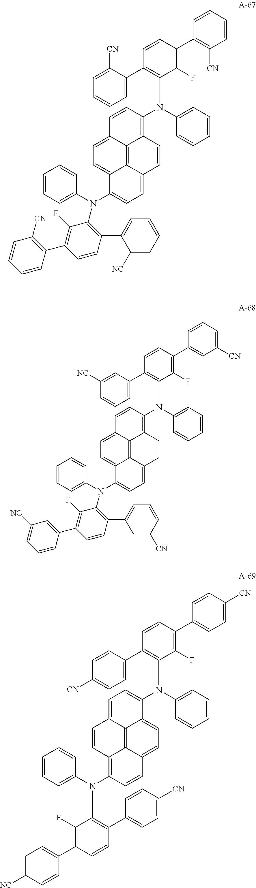


| TABLE 1 | ||||||
| Electric | ||||||
| voltage | current | Brightness | CIE(X) | CIE(Y) | ||
| Ex. 1 | 4.36 | 10 | 606 | 0.136 | 0.142 |
| Ex. 2 | 4.45 | 10 | 618 | 0.135 | 0.133 |
| Ex. 3 | 4.46 | 10 | 683 | 0.131 | 0.157 |
| Ex. 4 | 4.49 | 10 | 583 | 0.137 | 0.136 |
| Ex. 5 | 4.54 | 10 | 641 | 0.137 | 0.176 |
| Com. Ex. 1 | 6.7 | 10 | 526 | 0.136 | 0.188 |


| TABLE 2 | ||||||
| Electric | ||||||
| voltage | current | Brightness | CIE(X) | CIE(Y) | ||
| Ex. 6 | 4.73 | 10 | 614 | 0.139 | 0.130 |
| Ex. 7 | 4.61 | 10 | 628 | 0.140 | 0.131 |
| Ex. 8 | 4.42 | 10 | 659 | 0.139 | 0.143 |
| Ex. 9 | 4.65 | 10 | 602 | 0.132 | 0.136 |
| Com. Ex. 2 | 6.7 | 10 | 526 | 0.136 | 0.188 |


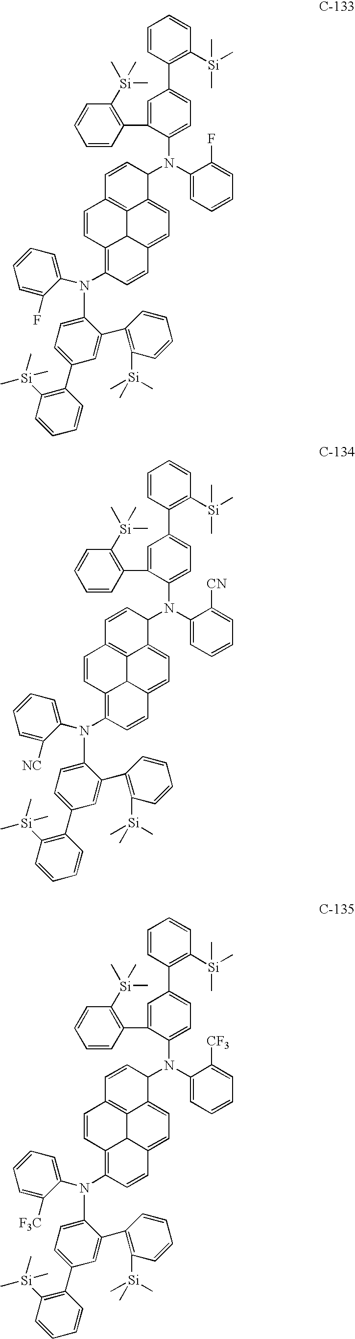


| TABLE 3 | ||||||
| Electric | ||||||
| voltage | current | Brightness | CIE(X) | CIE(Y) | ||
| Ex. 1 | 4.30 | 10 | 723 | 0.132 | 0.152 |
| Ex. 2 | 4.26 | 10 | 733 | 0.135 | 0.157 |
| Com. Ex. 1 | 6.7 | 10 | 526 | 0.136 | 0.188 |
Claims (20)


Applications Claiming Priority (2)
| Application Number | Priority Date | Filing Date | Title |
|---|---|---|---|
| KR1020080123423A KR101359701B1 (en) | 2008-12-05 | 2008-12-05 | Blue color fluorescent material and Organic electroluminescent device using the same |
| KR10-2008-0123423 | 2008-12-05 |
Publications (2)
| Publication Number | Publication Date |
|---|---|
| US20100141124A1 US20100141124A1 (en) | 2010-06-10 |
| US8835020B2 true US8835020B2 (en) | 2014-09-16 |
Family
ID=42230306
Family Applications (1)
| Application Number | Title | Priority Date | Filing Date |
|---|---|---|---|
| US12/591,796 Active 2031-01-09 US8835020B2 (en) | 2008-12-05 | 2009-12-01 | Blue fluorescent composition and organic electroluminescent device using the same |
Country Status (4)
| Country | Link |
|---|---|
| US (1) | US8835020B2 (en) |
| KR (1) | KR101359701B1 (en) |
| CN (1) | CN101747889B (en) |
| TW (1) | TWI415921B (en) |
Cited By (2)
| Publication number | Priority date | Publication date | Assignee | Title |
|---|---|---|---|---|
| US20110156011A1 (en) * | 2009-12-29 | 2011-06-30 | Jong-Kwan Bin | Blue fluorescence compound and organic electroluminescence device using the same |
| US12178120B2 (en) | 2020-08-13 | 2024-12-24 | Samsung Electronics Co., Ltd. | Amine compound and organic light-emitting device including the same |
Families Citing this family (17)
| Publication number | Priority date | Publication date | Assignee | Title |
|---|---|---|---|---|
| KR101294236B1 (en) * | 2009-07-10 | 2013-08-07 | 엘지디스플레이 주식회사 | Blue color fluorescent material and Organic electroluminescent device using the same |
| JP5478615B2 (en) * | 2009-12-16 | 2014-04-23 | 出光興産株式会社 | Organic luminescent medium |
| JP5198657B2 (en) * | 2009-12-16 | 2013-05-15 | 出光興産株式会社 | Organic luminescent medium |
| JP5152210B2 (en) * | 2010-01-27 | 2013-02-27 | 東洋インキScホールディングス株式会社 | Material for organic electroluminescence device and use thereof |
| JP5617432B2 (en) * | 2010-08-20 | 2014-11-05 | 東洋インキScホールディングス株式会社 | Organic electroluminescence device |
| JP5110198B1 (en) * | 2011-12-02 | 2012-12-26 | 東洋インキScホールディングス株式会社 | Material for organic electroluminescence device and use thereof |
| KR101673521B1 (en) * | 2012-03-02 | 2016-11-08 | 삼성디스플레이 주식회사 | Pyrene-based compound, organic light emitting diode comprising the same and organic light emitting apparatus comprising the same |
| JP2014177441A (en) * | 2013-03-15 | 2014-09-25 | Idemitsu Kosan Co Ltd | Aromatic amine derivative, material for organic electroluminescent element, organic electroluminescent element, and electronic equipment |
| KR102336769B1 (en) * | 2014-02-21 | 2021-12-09 | 가부시키가이샤 한도오따이 에네루기 켄큐쇼 | Organic compound, light-emitting element, display module, lighting module, light-emitting device, display device, electronic device, and lighting device |
| KR102210266B1 (en) * | 2014-04-29 | 2021-02-01 | 에스에프씨 주식회사 | An electroluminescent compound and an electroluminescent device comprising the same |
| US9902687B2 (en) * | 2014-09-19 | 2018-02-27 | Idemitsu Kosan Co., Ltd. | Compound |
| JP2016108290A (en) * | 2014-12-09 | 2016-06-20 | 三星ディスプレイ株式會社Samsung Display Co.,Ltd. | Amine derivative and organic electroluminescent element |
| WO2018095382A1 (en) * | 2016-11-23 | 2018-05-31 | 广州华睿光电材料有限公司 | Aromatic amine derivative, preparation method therefor, and uses thereof |
| CN108047062B (en) * | 2017-12-29 | 2019-07-16 | 广州华睿光电材料有限公司 | Aromatic amine derivant and organic electronic device |
| CN113620816B (en) * | 2020-05-08 | 2025-01-10 | 北京夏禾科技有限公司 | Aromatic amine derivatives organic electroluminescent materials and devices |
| CN113248426B (en) * | 2021-04-07 | 2024-10-18 | 浙江华显光电科技有限公司 | Heterocyclic triarylamine compound and organic photoelectric device containing same |
| CN114230473B (en) * | 2021-12-22 | 2024-06-11 | 安徽秀朗新材料科技有限公司 | Pyrene-based aromatic amine compound, preparation method thereof and application thereof as organic electroluminescent material |
Citations (6)
| Publication number | Priority date | Publication date | Assignee | Title |
|---|---|---|---|---|
| US20030227001A1 (en) * | 2002-06-04 | 2003-12-11 | Canon Kabushiki Kaisha | Organic photoluminescent polymers with improved stability |
| KR20040057862A (en) | 2002-12-24 | 2004-07-02 | 엘지전자 주식회사 | organic electroluminescence device |
| US20040137270A1 (en) * | 2002-12-24 | 2004-07-15 | Lg Electronics Inc. | Organic electroluminescent device |
| US20070009758A1 (en) | 2003-03-20 | 2007-01-11 | Masakazu Funahashi | Aromatic amine derivative and organic electroluminescent element made with the same |
| KR20070115588A (en) | 2006-06-01 | 2007-12-06 | 에스에프씨 주식회사 | Blue light emitting compound and organic light emitting device using the same |
| US20100052526A1 (en) * | 2008-08-26 | 2010-03-04 | Sfc Co., Ltd. | Pyrene compounds and organic electroluminescent devices using the same |
Family Cites Families (1)
| Publication number | Priority date | Publication date | Assignee | Title |
|---|---|---|---|---|
| US8173272B2 (en) * | 2006-03-23 | 2012-05-08 | Lg Chem, Ltd. | Diamine derivatives, preparation method thereof and organic electronic device using the same |
-
2008
- 2008-12-05 KR KR1020080123423A patent/KR101359701B1/en active Active
-
2009
- 2009-11-20 CN CN200910226139.7A patent/CN101747889B/en active Active
- 2009-12-01 US US12/591,796 patent/US8835020B2/en active Active
- 2009-12-04 TW TW098141570A patent/TWI415921B/en active
Patent Citations (7)
| Publication number | Priority date | Publication date | Assignee | Title |
|---|---|---|---|---|
| US20030227001A1 (en) * | 2002-06-04 | 2003-12-11 | Canon Kabushiki Kaisha | Organic photoluminescent polymers with improved stability |
| KR20040057862A (en) | 2002-12-24 | 2004-07-02 | 엘지전자 주식회사 | organic electroluminescence device |
| US20040137270A1 (en) * | 2002-12-24 | 2004-07-15 | Lg Electronics Inc. | Organic electroluminescent device |
| CN1535089A (en) | 2002-12-24 | 2004-10-06 | Lg������ʽ���� | Organic Electroluminescent Devices |
| US20070009758A1 (en) | 2003-03-20 | 2007-01-11 | Masakazu Funahashi | Aromatic amine derivative and organic electroluminescent element made with the same |
| KR20070115588A (en) | 2006-06-01 | 2007-12-06 | 에스에프씨 주식회사 | Blue light emitting compound and organic light emitting device using the same |
| US20100052526A1 (en) * | 2008-08-26 | 2010-03-04 | Sfc Co., Ltd. | Pyrene compounds and organic electroluminescent devices using the same |
Cited By (3)
| Publication number | Priority date | Publication date | Assignee | Title |
|---|---|---|---|---|
| US20110156011A1 (en) * | 2009-12-29 | 2011-06-30 | Jong-Kwan Bin | Blue fluorescence compound and organic electroluminescence device using the same |
| US9126892B2 (en) * | 2009-12-29 | 2015-09-08 | Lg Display Co., Ltd. | Blue fluorescence compound and organic electroluminescence device using the same |
| US12178120B2 (en) | 2020-08-13 | 2024-12-24 | Samsung Electronics Co., Ltd. | Amine compound and organic light-emitting device including the same |
Also Published As
| Publication number | Publication date |
|---|---|
| TW201026818A (en) | 2010-07-16 |
| US20100141124A1 (en) | 2010-06-10 |
| TWI415921B (en) | 2013-11-21 |
| KR20100064815A (en) | 2010-06-15 |
| KR101359701B1 (en) | 2014-02-11 |
| CN101747889B (en) | 2015-09-09 |
| CN101747889A (en) | 2010-06-23 |
Similar Documents
| Publication | Publication Date | Title |
|---|---|---|
| US8835020B2 (en) | Blue fluorescent composition and organic electroluminescent device using the same | |
| US11618754B2 (en) | Nitrogen-containing compound, electronic component and electronic device including same | |
| US9882146B2 (en) | Heterocyclic compound and organic electronic element containing same | |
| US11133472B1 (en) | Organic light-emitting diode having long lifespan, low voltage, and high efficiency property | |
| US8541113B2 (en) | Pyrene compounds and organic electroluminescent devices using the same | |
| US8986853B2 (en) | Red phosphorescent composition and organic electroluminescent device using the same | |
| US8906521B2 (en) | Organic electroluminescent device having triptycene derivative material | |
| US10155773B2 (en) | Organic electroluminescent compound and organic electroluminescent device | |
| US9299935B2 (en) | Nitrogen-containing heterocyclic compounds and organic electronic device comprising the same | |
| US20180009776A1 (en) | Novel organic compounds for organic light-emitting diode and organic light-emitting diode including the same | |
| US20120080670A1 (en) | Compound containing a 5-membered heterocycle and organic light-emitting diode using same, and terminal for same | |
| US20110315975A1 (en) | Material for use in phosphorescent device and organic electroluminescent device using same | |
| US8288014B2 (en) | Fluorene-containing compound and organic light emitting device employing the same | |
| US20100164371A1 (en) | Electron transporting-injection compound and organic electroluminescent device using the same | |
| US20200190122A1 (en) | Delayed fluorescent compound, and organic light emitting diode and organic light emitting display device including the same | |
| KR20140015202A (en) | Organic electroluminescent compound comprising acridine derivative and organic electroluminescent device comprising same | |
| US9284486B2 (en) | Blue fluorescent composition and organic electroluminescent device using the same | |
| KR20140086880A (en) | Novel organic compound and organic electroluminescent device comprising same | |
| US20130249968A1 (en) | Fused polycyclic compound and organic light emitting device using the same | |
| CN105745301B (en) | Novel light-emitting compound and organic light-emitting element including the same | |
| KR101415730B1 (en) | Aromatic compound derivatives and organic electroluminescent device using the same | |
| US20240147854A1 (en) | Novel boron compound and organic light-emitting diode including same | |
| KR101375542B1 (en) | Hole transport material containing thiophene derivative and organic light emitting device using same | |
| US20200251662A1 (en) | Thermally activated delayed fluorescence material, organic electroluminescent device, and display panel | |
| US20240260453A1 (en) | Organic Light-Emitting Compound And Organic Light-Emitting Device Comprising Same |
Legal Events
| Date | Code | Title | Description |
|---|---|---|---|
| AS | Assignment |
Owner name: LG DISPLAY CO., LTD.,KOREA, REPUBLIC OF Free format text: ASSIGNMENT OF ASSIGNORS INTEREST;ASSIGNORS:LEE, SEUNG-JAE;SONG, IN-BUM;KIM, JUNG-KEUN;AND OTHERS;REEL/FRAME:023629/0033 Effective date: 20091120 Owner name: LG DISPLAY CO., LTD., KOREA, REPUBLIC OF Free format text: ASSIGNMENT OF ASSIGNORS INTEREST;ASSIGNORS:LEE, SEUNG-JAE;SONG, IN-BUM;KIM, JUNG-KEUN;AND OTHERS;REEL/FRAME:023629/0033 Effective date: 20091120 |
|
| FEPP | Fee payment procedure |
Free format text: PAYOR NUMBER ASSIGNED (ORIGINAL EVENT CODE: ASPN); ENTITY STATUS OF PATENT OWNER: LARGE ENTITY |
|
| STCF | Information on status: patent grant |
Free format text: PATENTED CASE |
|
| MAFP | Maintenance fee payment |
Free format text: PAYMENT OF MAINTENANCE FEE, 4TH YEAR, LARGE ENTITY (ORIGINAL EVENT CODE: M1551) Year of fee payment: 4 |
|
| MAFP | Maintenance fee payment |
Free format text: PAYMENT OF MAINTENANCE FEE, 8TH YEAR, LARGE ENTITY (ORIGINAL EVENT CODE: M1552); ENTITY STATUS OF PATENT OWNER: LARGE ENTITY Year of fee payment: 8 |
|
| MAFP | Maintenance fee payment |
Free format text: PAYMENT OF MAINTENANCE FEE, 12TH YEAR, LARGE ENTITY (ORIGINAL EVENT CODE: M1553); ENTITY STATUS OF PATENT OWNER: LARGE ENTITY Year of fee payment: 12 |