US8820349B2 - Control valve for adjusting a process medium flow of a technical process installation - Google Patents
Control valve for adjusting a process medium flow of a technical process installation Download PDFInfo
- Publication number
- US8820349B2 US8820349B2 US13/760,415 US201313760415A US8820349B2 US 8820349 B2 US8820349 B2 US 8820349B2 US 201313760415 A US201313760415 A US 201313760415A US 8820349 B2 US8820349 B2 US 8820349B2
- Authority
- US
- United States
- Prior art keywords
- thermoelectric element
- valve
- valve seat
- control valve
- valve member
- Prior art date
- Legal status (The legal status is an assumption and is not a legal conclusion. Google has not performed a legal analysis and makes no representation as to the accuracy of the status listed.)
- Expired - Fee Related
Links
Images


Classifications
-
- F—MECHANICAL ENGINEERING; LIGHTING; HEATING; WEAPONS; BLASTING
- F16—ENGINEERING ELEMENTS AND UNITS; GENERAL MEASURES FOR PRODUCING AND MAINTAINING EFFECTIVE FUNCTIONING OF MACHINES OR INSTALLATIONS; THERMAL INSULATION IN GENERAL
- F16K—VALVES; TAPS; COCKS; ACTUATING-FLOATS; DEVICES FOR VENTING OR AERATING
- F16K37/00—Special means in or on valves or other cut-off apparatus for indicating or recording operation thereof, or for enabling an alarm to be given
- F16K37/0025—Electrical or magnetic means
-
- F—MECHANICAL ENGINEERING; LIGHTING; HEATING; WEAPONS; BLASTING
- F16—ENGINEERING ELEMENTS AND UNITS; GENERAL MEASURES FOR PRODUCING AND MAINTAINING EFFECTIVE FUNCTIONING OF MACHINES OR INSTALLATIONS; THERMAL INSULATION IN GENERAL
- F16K—VALVES; TAPS; COCKS; ACTUATING-FLOATS; DEVICES FOR VENTING OR AERATING
- F16K37/00—Special means in or on valves or other cut-off apparatus for indicating or recording operation thereof, or for enabling an alarm to be given
-
- F—MECHANICAL ENGINEERING; LIGHTING; HEATING; WEAPONS; BLASTING
- F16—ENGINEERING ELEMENTS AND UNITS; GENERAL MEASURES FOR PRODUCING AND MAINTAINING EFFECTIVE FUNCTIONING OF MACHINES OR INSTALLATIONS; THERMAL INSULATION IN GENERAL
- F16K—VALVES; TAPS; COCKS; ACTUATING-FLOATS; DEVICES FOR VENTING OR AERATING
- F16K31/00—Actuating devices; Operating means; Releasing devices
- F16K31/02—Actuating devices; Operating means; Releasing devices electric; magnetic
- F16K31/025—Actuating devices; Operating means; Releasing devices electric; magnetic actuated by thermo-electric means
-
- H—ELECTRICITY
- H10—SEMICONDUCTOR DEVICES; ELECTRIC SOLID-STATE DEVICES NOT OTHERWISE PROVIDED FOR
- H10N—ELECTRIC SOLID-STATE DEVICES NOT OTHERWISE PROVIDED FOR
- H10N10/00—Thermoelectric devices comprising a junction of dissimilar materials, i.e. devices exhibiting Seebeck or Peltier effects
- H10N10/10—Thermoelectric devices comprising a junction of dissimilar materials, i.e. devices exhibiting Seebeck or Peltier effects operating with only the Peltier or Seebeck effects
-
- H—ELECTRICITY
- H10—SEMICONDUCTOR DEVICES; ELECTRIC SOLID-STATE DEVICES NOT OTHERWISE PROVIDED FOR
- H10N—ELECTRIC SOLID-STATE DEVICES NOT OTHERWISE PROVIDED FOR
- H10N10/00—Thermoelectric devices comprising a junction of dissimilar materials, i.e. devices exhibiting Seebeck or Peltier effects
- H10N10/10—Thermoelectric devices comprising a junction of dissimilar materials, i.e. devices exhibiting Seebeck or Peltier effects operating with only the Peltier or Seebeck effects
- H10N10/17—Thermoelectric devices comprising a junction of dissimilar materials, i.e. devices exhibiting Seebeck or Peltier effects operating with only the Peltier or Seebeck effects characterised by the structure or configuration of the cell or thermocouple forming the device
-
- Y—GENERAL TAGGING OF NEW TECHNOLOGICAL DEVELOPMENTS; GENERAL TAGGING OF CROSS-SECTIONAL TECHNOLOGIES SPANNING OVER SEVERAL SECTIONS OF THE IPC; TECHNICAL SUBJECTS COVERED BY FORMER USPC CROSS-REFERENCE ART COLLECTIONS [XRACs] AND DIGESTS
- Y10—TECHNICAL SUBJECTS COVERED BY FORMER USPC
- Y10T—TECHNICAL SUBJECTS COVERED BY FORMER US CLASSIFICATION
- Y10T137/00—Fluid handling
- Y10T137/8158—With indicator, register, recorder, alarm or inspection means
-
- Y—GENERAL TAGGING OF NEW TECHNOLOGICAL DEVELOPMENTS; GENERAL TAGGING OF CROSS-SECTIONAL TECHNOLOGIES SPANNING OVER SEVERAL SECTIONS OF THE IPC; TECHNICAL SUBJECTS COVERED BY FORMER USPC CROSS-REFERENCE ART COLLECTIONS [XRACs] AND DIGESTS
- Y10—TECHNICAL SUBJECTS COVERED BY FORMER USPC
- Y10T—TECHNICAL SUBJECTS COVERED BY FORMER US CLASSIFICATION
- Y10T137/00—Fluid handling
- Y10T137/8376—Combined
Definitions
- the disclosure relates to a control valve for adjusting a process medium flow of a technical process installation, like a refinery, a food processing plant like a brewery, or a petrochemical plant or the like.
- a continuous power supply by means of an energy converter for electro-pneumatically operated positioners for use in technical process installations is known from DE 10 2006 011 503 A1.
- electrical power is to be provided out of the air pressure supply by utilizing a pressure difference between ambient air and a pressure of the air supply for actuating a control valve.
- a housing is provided with an interior to be traversed by a process medium.
- a valve seat is disposed inside the housing interior.
- a valve member is provided obstructing or clearing the valve seat wherein a flow cross section of the control valve can be altered according to a relative position between the valve member and the valve seat for adjusting the process medium flow to initiate a pressure change in the process medium flow between an upstream and a downstream duct section.
- An electrical consumer is provided.
- a thermoelectric element is coupled to supply electrical power to the electrical consumer. The thermoelectric element is disposed at a position in the housing interior for generating the electrical power resulting from a temperature difference that accompanies a pressure difference at a location of said position of the thermoelectric element.
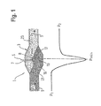
- FIG. 1 is a technical schematic sketch of a control valve according to an exemplary embodiment and which is connected to an installation conduit of the technical process installation, wherein the pressure conditions over the path of the flow through the control valve are indicated by means of a line below the sketch;
- FIG. 2 is a cross-sectional view of a control valve fitted in a technical process installation, wherein within the conduits and at the control valve, pressure conditions of the process fluid are represented graphically;
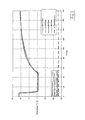
- FIG. 3 is a graph showing a temperature recording at a control valve over time for different differential pressures between an upstream and a downstream location at the control valve according to the exemplary embodiment.
- a control valve for adjusting a process medium flow of a technical process installation having a housing with an interior to be traversed by the process medium.
- the housing can, for example, be comprised of a downstream conduit connector portion, an upstream conduit connector portion, a baffle that separates the two connector portions from each other and possibly forms or receives a valve seat delimiting the valve passage, and a sleeve at the side of the control valve drive that often tightly seals the housing and through which an actuator rod or an actuator shaft extends.
- the valve seat represents a throttling point with a defined geometry between the upstream conduit connector portion and the downstream conduit connector portion of the housing.
- control valve At the upstream conduit connection as well as at the downstream conduit connection flange areas may be provided at which conduit pipes leading further within the technical process installation are to be connected.
- the control valve has a valve member or stopper part, in particular a valve cone, obstructing or clearing the valve seat.
- the valve member serves to alter the in particular narrowest passage cross section at the baffle between the valve member and the valve seat, in particular to open or to close the latter, in order to adjust the process medium flow, for example according to a control routine, in particular to adjust a pressure drop between the pressure prevailing in the upstream conduit portion of the control valve and the downstream conduit portion.
- control valve has an electrical consumer like a sensor, in particular a position sensor, a positioner, in particular a microchip, an electronic memory, a sender, an accumulator or the like. It shall be understood that the electrical consumer is to be considered as such also in the case that the control valve presents at least one electrical connection at which a consumer as named above can be connected.
- the control valve according to the exemplary embodiment additionally has a thermoelectric element in the housing interior coupled to the electrical consumer for supplying electrical power.
- electric power can be generated from the location of the disposal of the thermoelectric element, that is in direct vicinity to the valve member and/or to the valve seat in the housing interior, owing to a temperature difference that accompanies a pressure difference of the process medium flow.
- a constant, durable and reliable power supply is provided. This also holds if solid particles are entrained in the process medium flow, which causes a high level of wear for other power sources like turbines.
- thermoelectric element In order to obtain the highest possible energy yield from the thermoelectric element, preferably the thermoelectric element is to be disposed in a so-called “vena contracta” area, that is along a path of the flow traversing the control valve housing at a smallest flow cross section, in particular in a middle of the restricted flow channel.
- thermoelectric element With respect to an optimum arrangement, it is observed that a considerable temperature drop occurs within the process medium flow in the vicinity of metal components. In this way a simple and solid fitting is provided for mounting the thermoelectric element. Especially the valve cone, the valve member, or the valve seat can come into consideration as a mounting position for the thermoelectric element. Very good power generation results can be obtained if a high heat conductance at the mounting location of the thermoelectric element is exploited. It can be advantageous to provide the material of the mounting position for the thermoelectric element with a high thermal conductivity coefficient.
- thermoelectric element When the thermoelectric element is inserted a reference point is required, the fitting position of which is advantageously chosen to be in particular in the flow area at the side of the inlet of the control valve, for example either inside the flow channel or at a respective wall.
- thermoelectric elements are disposed in the same control valve housing which can provide a larger energy recovery.
- the thermoelectric elements may be connected in line with each other. It could, for example, be considered to mount an additional thermoelectric element also in the actuating air pressure circuit responsible for actuating the control valve.
- thermoelectric element is positioned in the area of an especially narrow flow passage between the valve member and the valve seat. Since the position of the minimum flow passage cross section is variable depending on the position of the valve member, an in particular flat and/or foil-type thermoelectric element can be provided in order to ensure that in every position of the valve member the thermoelectric element is disposed in the area of the minimum flow passage cross section.
- thermoelectric element can also be disposed within the process medium flow in the passage between the valve member and the valve seat, i.e. at a distance therefrom. At the narrowest flow cross section the highest pressure drop and the highest temperature gradient is to be expected.
- thermoelectric element can be disposed at the valve member, in particular at an outer side of the valve member, and/or at the valve seat, in particular at an inside of the valve seat.
- the valve seat can be designed as a separately mountable component, like an insert sleeve, attached to an inner housing part, in particular with a screw connection, or is designed as an integral component of the inner housing part.
- the valve seat has a revolving sealing surface that can cooperate in a sealing manner with a respective revolving sealing surface of the valve member, obstructing the passage of the control valve. Provisions can be made to dispose a thermoelectric element at the position of the surface of the valve member and/or of the valve seat.
- thermoelectric element is disposed at a profiling like a step, an offset, an undercut of the valve seat and/or of the valve member. It became apparent that for such profilings supercritical flow conditions, which is where the largest temperature gradients occur, will arise first in case of a gradual increase of the pressure drop of the process medium.
- thermoelectric element is positioned within a flow passage between the valve member and the valve seat at a distance from the latter, wherein in particular the point of disposal of the thermoelectric element is positioned downstream of the valve seat and/or of the valve member.
- the housing has a downstream conduit section and an upstream conduit section.
- the thermoelectric element can be positioned inside the downstream conduit section, in particular at a distance to a conduit wall and/or at an inner side of the conduit wall.
- the conduit wall to be used is the one reached first by the process medium flow after leaving the valve seat and/or to which the flow has the smallest distance.
- thermoelectric element can in particular be positioned at or in the area of an outer surface of the valve member facing the valve seat. This outer surface can be disposed at a lateral half of the valve member facing the downstream conduit section.
- thermoelectric element is disposed at a tangential line at the outer surface of the valve member closest to the downstream conduit section, preferably aligned with the positioning direction of the valve member.
- thermoelectric element is positioned at an inner side of the valve seat facing the valve member, which inner side is disposed at a lateral half close to the downstream conduit section.
- the area of disposal of the thermoelectric element is selected such that it is facing the upstream conduit section.
- thermoelectric element has a metal to metal contact as a basic structure, wherein electrical energy flows can be generated resulting from a temperature difference with respect to a reference point.
- thermoelectric elements are preferably connected in large numbers in series.
- thermoelectric element in particular the thermoelectric series connection, forms a thin plate or film structure.
- the plate or film structure can be disposed and dimensioned such that at least a portion of it extends into an area of the largest pressure drop of the process medium flow along the flow.
- the plate or film structure can be a silicon wafer structure.
- the first layer, the wafer is disposed at the side of the valve seat and/or at the side of the valve member, wherein the wafer is attached, in particular glued, to the respective outer surface.
- the silicon layer disposed above the wafer is positioned at the side of the process medium flow.
- a multitude of thermoelectric pairs of compound material may be introduced between the wafer and the silicon layer in a sandwich arrangement.
- the exemplary embodiment relates to a method for providing electrical power for an electrical consumer like an I/P converter, a positioner, a sensor, like a position sensor, a wireless transmission or the like.
- the provision of electrical power can be for the electrical consumer of a control valve.
- the conduit system of the technical process installation is/comes to be provided with a cross section restriction that is for example formed by a fixed baffle for flow measurement or a throttling point of the process valve, in particular one according to exemplary embodiment.
- thermoelectric element is disposed within the process flow in the area of the cross section restriction, for example directly downstream from it, which element is being coupled to the electrical consumer for supplying electrical power, and electrical power is generated at the location of the disposal of the thermoelectric element by means of a temperature difference that accompanies a pressure difference, to be conducted to the electrical consumer.
- thermoelectric element In case of the disposal of the thermoelectric element inside the housing of a control valve, the latter has a valve seat and a valve member obstructing or clearing the valve seat. A flow cross section of the control valve can be altered according to the relative position between the valve member and the valve seat. In this way a pressure change in the process medium flow, in particular between the upstream and the downstream duct section, can be initiated.
- the electrical consumer shall be supplied by the provided energy.
- a thermoelectric element In the inside of the housing a thermoelectric element is disposed, immersed in the stream of the process medium. The thermoelectric element is coupled to the electrical consumer. At the location of the disposal of the thermoelectric element electrical power is generated by the thermoelectric element by means of a temperature difference that accompanies a pressure difference, to be conducted to the electrical consumer.
- a control valve 1 according to an exemplary embodiment is represented schematically in so far as it comprises a housing 3 .
- the control valve 1 is actuated by a pneumatic control drive not represented in detail.
- the actuating rod 5 of the drive enters the inside 11 of the housing 3 through an opening 7 formed in the housing and has at its end and in particular cone shaped valve member 13 .
- the pneumatic control drive is controlled by a positioner (not represented) that moves the valve member 13 up and down in order to adjust the process medium flow S.
- valve seat 15 is provided that cooperates with the valve member 13 for obstructing a valve passage 17 .
- the valve seat 15 structurally separates an upstream conduit section 21 from a downstream conduit section 23 of the housing 3 of the control valve 1 .
- the control valve generates, as a function of the position of the valve member 13 , a pressure drop between the flow pressure p 1 prevailing in the upstream conduit section 21 and the flow pressure p 2 prevailing in the downstream conduit section 21 .
- the largest pressure drop is to be expected in the circle B, wherein the value of the flow pressure P is represented qualitatively below the schematic sketch in FIG. 1 by the path of the graph.
- the minimum pressure pmin prevails in the area of the minimum passage cross section between the valve seat 15 and the valve member 13 , that is in particular the passage area downstream with respect to the valve member sides, indicated by the delimited circle line B in FIG. 1 .
- thermoelectric element For the control valve 1 according to the exemplary embodiment a so-called thermoelectric element is to be provided in the area of the expected largest medium velocity, which corresponds to the lowest pressure (largest pressure drop), wherein the thermoelectric element utilizes a temperature difference for generating electrical power.
- thermoelectric element is also to be disposed at other locations within the control valve housing where a sufficiently large pressure drop and thus a sufficiently large temperature gradient is produced, for example making use of built-in baffles or other cross section restrictions. Particularly advantageous are cross section restrictions in which a supercritical flow can be expected.
- thermoelectric element inside the process medium flow is very well suited to generate power for electronic components in the direct vicinity of the control valve, like a position sensor, a signal sender, a positioner, an I/P converter etc.
- FIG. 3 a graph is shown representing the measured temperature at a baffle for different pressure drops within the process medium of 1.5 bar to 4 bar.
- a temperature profile relatively void of deviations is achievable even for low process medium flow pressures, whereby a reliable and predictable power generation by the thermoelectric element is ensured. Consequently, even for the strong variation of the process medium flow a constant power supply can be achieved for the electrical consumer.
- the straight dashed (theoretic) line at about ⁇ 26° C. shown in FIG. 3 represents the theoretic course of the temperature over time, which temperature would occur for an adiabatic isentropic relaxation with respect to the initial temperature according to mathematical iteration.
- FIG. 2 shows a cross-sectional view of a control valve according to the exemplary embodiment according to the schematic sketch in FIG. 1 .
- valve seat 15 is inserted as a separate component at an inner housing part of the control valve 1 , in particular by means of a screw connection.
- thermoelectric element having reference numeral 31
- a suitable location for disposing the thermoelectric element is for example within the passage 17 at the smallest cross-sectional area between the valve member 13 and the valve seat 15 .
- a further suitable position is the outer surface of the cone-shaped valve member 13 , in particular in case that a flat thermoelectric element is used. The thermoelectric element can then extend across a large area of the valve member 13 .
- the passage 17 is provided rather at the downstream side of the valve member 13 , which is why the suitable area for the thermoelectric element is at that location. Furthermore, the thermoelectric element can be disposed within the passage 17 or also within the downstream conduit section 23 or at its inner surface 33 , which is where higher temperature gradients can be expected.
- thermoelectric element is disposed at the valve member 13
- an electric line like a cable, (not represented) can lead to an electrical consumer via the valve member 13 and the actuator rod 5 .
- the electric line can correspondingly be laid through sections of the housing 3 of the control valve 1 .
- thermoelectric element can be comprised of many individual elements preferably formed by a thin film structure and having a thickness of a few millimeters, preferably 1 to 2 mm.
- a thin film generator the product MPG-D651 or MPG-D751 of the company Mikropelt GmbH can be cited.
- Such a thin film generator is formed in a kind of sandwich structure in which a heat plate as well as a silicon substrate are superimposed on each other, wherein between the two layers so-called n-legs and p-legs are disposed.
- These thin film generators are particularly suitable to be disposed directly at the inner/outer surface of the valve seat 15 or the valve member 13 .
- thermoelectric elements within the process medium flows.
Landscapes
- Engineering & Computer Science (AREA)
- General Engineering & Computer Science (AREA)
- Mechanical Engineering (AREA)
- Electrically Driven Valve-Operating Means (AREA)
- Lift Valve (AREA)
- Fluid-Driven Valves (AREA)
- Flow Control (AREA)
- Temperature-Responsive Valves (AREA)
Applications Claiming Priority (3)
| Application Number | Priority Date | Filing Date | Title |
|---|---|---|---|
| DE201210002316 DE102012002316A1 (de) | 2012-02-06 | 2012-02-06 | Stellventil zum Einstellen einer Prozessfluidströmung in einer prozesstechnischen Anlage |
| DE102012002316 | 2012-02-06 | ||
| DE102012002316.2 | 2012-02-06 |
Publications (2)
| Publication Number | Publication Date |
|---|---|
| US20130199637A1 US20130199637A1 (en) | 2013-08-08 |
| US8820349B2 true US8820349B2 (en) | 2014-09-02 |
Family
ID=47681592
Family Applications (1)
| Application Number | Title | Priority Date | Filing Date |
|---|---|---|---|
| US13/760,415 Expired - Fee Related US8820349B2 (en) | 2012-02-06 | 2013-02-06 | Control valve for adjusting a process medium flow of a technical process installation |
Country Status (3)
| Country | Link |
|---|---|
| US (1) | US8820349B2 (de) |
| EP (1) | EP2623829B1 (de) |
| DE (1) | DE102012002316A1 (de) |
Families Citing this family (2)
| Publication number | Priority date | Publication date | Assignee | Title |
|---|---|---|---|---|
| KR102411946B1 (ko) | 2015-07-08 | 2022-06-22 | 삼성전자주식회사 | 초임계 유체를 이용한 기판 처리장치와 이를 포함하는 기판 처리 시스템 및 이를 이용한 기판처리 방법 |
| DE102015016357B4 (de) | 2015-12-17 | 2023-06-29 | Samson Aktiengesellschaft | Stellventil einer prozesstechnischen Anlage |
Citations (7)
| Publication number | Priority date | Publication date | Assignee | Title |
|---|---|---|---|---|
| US952187A (en) * | 1909-06-01 | 1910-03-15 | James A Donnelly | Valve. |
| US1891374A (en) * | 1930-05-02 | 1932-12-20 | Ehemann William | Valve |
| US5586745A (en) * | 1995-06-05 | 1996-12-24 | The United States Of America As Represented By The United States Department Of Energy | Value for controlling flow of cryogenic fluid |
| US6544561B2 (en) * | 1997-03-17 | 2003-04-08 | The Lachlan Family Pty Ltd. | Aqueous metal bicarbonate solution and method of use |
| DE102004004930A1 (de) * | 2004-02-02 | 2005-08-25 | Rexroth Mecman Gmbh | Energieumwandlungseinheit sowie Verfahren zur Energieumwandlung |
| DE102006011503A1 (de) | 2006-03-14 | 2007-09-27 | Abb Research Ltd. | Stellungsregler mit elektropneumatischen Ventilen und Prozessautomatisierungsgerät |
| US7739994B2 (en) * | 2006-09-13 | 2010-06-22 | Caterpillar Inc. | Thermoelectric system for an engine |
Family Cites Families (3)
| Publication number | Priority date | Publication date | Assignee | Title |
|---|---|---|---|---|
| GB2140206A (en) * | 1983-05-20 | 1984-11-21 | British Petroleum Co Plc | Thermoelectric power generator associated with oil pipelines |
| DE102010029090A1 (de) * | 2010-05-18 | 2011-11-24 | Micropelt Gmbh | Thermogeneratoranordnung und Verfahren zum Herstellen einer Thermogeneratoranordnung |
| FR2962563B1 (fr) * | 2010-07-06 | 2012-09-07 | Commissariat Energie Atomique | Dispositif de distribution d'un fluide a module thermoelectrique. |
-
2012
- 2012-02-06 DE DE201210002316 patent/DE102012002316A1/de not_active Withdrawn
-
2013
- 2013-01-18 EP EP13000266.0A patent/EP2623829B1/de not_active Not-in-force
- 2013-02-06 US US13/760,415 patent/US8820349B2/en not_active Expired - Fee Related
Patent Citations (7)
| Publication number | Priority date | Publication date | Assignee | Title |
|---|---|---|---|---|
| US952187A (en) * | 1909-06-01 | 1910-03-15 | James A Donnelly | Valve. |
| US1891374A (en) * | 1930-05-02 | 1932-12-20 | Ehemann William | Valve |
| US5586745A (en) * | 1995-06-05 | 1996-12-24 | The United States Of America As Represented By The United States Department Of Energy | Value for controlling flow of cryogenic fluid |
| US6544561B2 (en) * | 1997-03-17 | 2003-04-08 | The Lachlan Family Pty Ltd. | Aqueous metal bicarbonate solution and method of use |
| DE102004004930A1 (de) * | 2004-02-02 | 2005-08-25 | Rexroth Mecman Gmbh | Energieumwandlungseinheit sowie Verfahren zur Energieumwandlung |
| DE102006011503A1 (de) | 2006-03-14 | 2007-09-27 | Abb Research Ltd. | Stellungsregler mit elektropneumatischen Ventilen und Prozessautomatisierungsgerät |
| US7739994B2 (en) * | 2006-09-13 | 2010-06-22 | Caterpillar Inc. | Thermoelectric system for an engine |
Also Published As
| Publication number | Publication date |
|---|---|
| DE102012002316A1 (de) | 2013-08-08 |
| EP2623829A3 (de) | 2015-04-15 |
| US20130199637A1 (en) | 2013-08-08 |
| EP2623829B1 (de) | 2018-11-14 |
| EP2623829A2 (de) | 2013-08-07 |
Similar Documents
| Publication | Publication Date | Title |
|---|---|---|
| KR100432632B1 (ko) | 압력식 유량제어장치에 있어서의 유량이상검지방법 | |
| US5123433A (en) | Ultrasonic flow nozzle cleaning apparatus | |
| JP3595554B2 (ja) | 圧力フィードバック、動的補正、および診断機能を備えたバルブ位置制御装置 | |
| CN101815932B (zh) | 基于知识的阀门控制方法 | |
| JP6490744B2 (ja) | 圧力バランス式流体圧調節器 | |
| JP5539900B2 (ja) | スプール・バルブ用アクチュエータ | |
| CN101255882A (zh) | 用于诊断调节机构的方法和装置 | |
| CN104903808B (zh) | 压力调节器 | |
| CN101960193A (zh) | 用于检测控制阀部件失效的诊断方法 | |
| CN102575782A (zh) | 微型机械装置和控制方法 | |
| KR20200047712A (ko) | 밸브, 밸브의 이상 진단 방법, 및 컴퓨터 프로그램 | |
| CN103917933B (zh) | 压力调节器 | |
| CN101900152A (zh) | 以电子方式确定阀门系统的磨损状态的方法及阀门系统 | |
| CN110360375A (zh) | 阀门维护状态的检测 | |
| US20040107767A1 (en) | Valve technology | |
| US20130199637A1 (en) | Control valve for adjusting a process medium flow of a technical process installation | |
| CN120444431B (zh) | 一种基于数据检测自动调压的先导阀控制方法及装置 | |
| US6631736B2 (en) | Device for metering a gaseous medium | |
| US20140034158A1 (en) | Apparatus for monitoring of valves and method of operating the same | |
| US7278320B1 (en) | Omni-directional pressure pickup probe | |
| CN101206483A (zh) | 用于诊断通过辅助能进行驱动的调整机构的方法 | |
| JP2007133829A (ja) | 流体制御装置と圧力調節弁と制御方法 | |
| JP4554634B2 (ja) | フランジ結合部材およびそれを使用したパイプラインの異常検出装置 | |
| JP3984218B2 (ja) | パイプラインの異常検出方法およびその装置 | |
| US20110284779A1 (en) | Method and apparatus for controlling a high-pressure valve |
Legal Events
| Date | Code | Title | Description |
|---|---|---|---|
| AS | Assignment |
Owner name: SAMSON AKTIENGESELLSCHAFT, GERMANY Free format text: ASSIGNMENT OF ASSIGNORS INTEREST;ASSIGNOR:KIESBAUER, JOERG;REEL/FRAME:029764/0162 Effective date: 20130104 |
|
| STCF | Information on status: patent grant |
Free format text: PATENTED CASE |
|
| MAFP | Maintenance fee payment |
Free format text: PAYMENT OF MAINTENANCE FEE, 4TH YEAR, LARGE ENTITY (ORIGINAL EVENT CODE: M1551) Year of fee payment: 4 |
|
| FEPP | Fee payment procedure |
Free format text: MAINTENANCE FEE REMINDER MAILED (ORIGINAL EVENT CODE: REM.); ENTITY STATUS OF PATENT OWNER: LARGE ENTITY |
|
| LAPS | Lapse for failure to pay maintenance fees |
Free format text: PATENT EXPIRED FOR FAILURE TO PAY MAINTENANCE FEES (ORIGINAL EVENT CODE: EXP.); ENTITY STATUS OF PATENT OWNER: LARGE ENTITY |
|
| STCH | Information on status: patent discontinuation |
Free format text: PATENT EXPIRED DUE TO NONPAYMENT OF MAINTENANCE FEES UNDER 37 CFR 1.362 |
|
| FP | Lapsed due to failure to pay maintenance fee |
Effective date: 20220902 |