US8820034B1 - Low thermal bridge building components - Google Patents

Low thermal bridge building components Download PDF

Info

Publication number
US8820034B1
US8820034B1 US14/104,734 US201314104734A US8820034B1 US 8820034 B1 US8820034 B1 US 8820034B1 US 201314104734 A US201314104734 A US 201314104734A US 8820034 B1 US8820034 B1 US 8820034B1
Authority
US
United States
Prior art keywords
low thermal
thermal bridge
building component
flanges
bridge building
Prior art date
Legal status (The legal status is an assumption and is not a legal conclusion. Google has not performed a legal analysis and makes no representation as to the accuracy of the status listed.)
Expired - Fee Related
Application number
US14/104,734
Inventor
Kenneth D. Watts
Donald G. M. Watts
Current Assignee (The listed assignees may be inaccurate. Google has not performed a legal analysis and makes no representation or warranty as to the accuracy of the list.)
Thermal Framing LLC
Original Assignee
Thermal Framing LLC
Priority date (The priority date is an assumption and is not a legal conclusion. Google has not performed a legal analysis and makes no representation as to the accuracy of the date listed.)
Filing date
Publication date
Priority claimed from US13/778,113 external-priority patent/US8640429B1/en
Application filed by Thermal Framing LLC filed Critical Thermal Framing LLC
Priority to US14/104,734 priority Critical patent/US8820034B1/en
Assigned to Thermal Framing, LLC. reassignment Thermal Framing, LLC. ASSIGNMENT OF ASSIGNORS INTEREST (SEE DOCUMENT FOR DETAILS). Assignors: WATTS, DONALD GENE MCINTYRE, WATTS, KENNETH DONALD
Application granted granted Critical
Publication of US8820034B1 publication Critical patent/US8820034B1/en
Expired - Fee Related legal-status Critical Current
Anticipated expiration legal-status Critical

Links

Images

Classifications

    • EFIXED CONSTRUCTIONS
    • E04BUILDING
    • E04CSTRUCTURAL ELEMENTS; BUILDING MATERIALS
    • E04C3/00Structural elongated elements designed for load-supporting
    • E04C3/02Joists; Girders, trusses, or trusslike structures, e.g. prefabricated; Lintels; Transoms; Braces
    • E04C3/12Joists; Girders, trusses, or trusslike structures, e.g. prefabricated; Lintels; Transoms; Braces of wood, e.g. with reinforcements, with tensioning members
    • E04C3/16Joists; Girders, trusses, or trusslike structures, e.g. prefabricated; Lintels; Transoms; Braces of wood, e.g. with reinforcements, with tensioning members with apertured web, e.g. trusses
    • EFIXED CONSTRUCTIONS
    • E04BUILDING
    • E04BGENERAL BUILDING CONSTRUCTIONS; WALLS, e.g. PARTITIONS; ROOFS; FLOORS; CEILINGS; INSULATION OR OTHER PROTECTION OF BUILDINGS
    • E04B2/00Walls, e.g. partitions, for buildings; Wall construction with regard to insulation; Connections specially adapted to walls
    • E04B2/74Removable non-load-bearing partitions; Partitions with a free upper edge
    • E04B2/7407Removable non-load-bearing partitions; Partitions with a free upper edge assembled using frames with infill panels or coverings only; made-up of panels and a support structure incorporating posts
    • E04B2/7409Removable non-load-bearing partitions; Partitions with a free upper edge assembled using frames with infill panels or coverings only; made-up of panels and a support structure incorporating posts special measures for sound or thermal insulation, including fire protection
    • E04B2/7412Posts or frame members specially adapted for reduced sound or heat transmission
    • EFIXED CONSTRUCTIONS
    • E04BUILDING
    • E04CSTRUCTURAL ELEMENTS; BUILDING MATERIALS
    • E04C3/00Structural elongated elements designed for load-supporting
    • E04C3/02Joists; Girders, trusses, or trusslike structures, e.g. prefabricated; Lintels; Transoms; Braces
    • E04C3/12Joists; Girders, trusses, or trusslike structures, e.g. prefabricated; Lintels; Transoms; Braces of wood, e.g. with reinforcements, with tensioning members
    • E04C3/122Laminated
    • EFIXED CONSTRUCTIONS
    • E04BUILDING
    • E04CSTRUCTURAL ELEMENTS; BUILDING MATERIALS
    • E04C3/00Structural elongated elements designed for load-supporting
    • E04C3/02Joists; Girders, trusses, or trusslike structures, e.g. prefabricated; Lintels; Transoms; Braces
    • E04C3/12Joists; Girders, trusses, or trusslike structures, e.g. prefabricated; Lintels; Transoms; Braces of wood, e.g. with reinforcements, with tensioning members
    • E04C3/14Joists; Girders, trusses, or trusslike structures, e.g. prefabricated; Lintels; Transoms; Braces of wood, e.g. with reinforcements, with tensioning members with substantially solid, i.e. unapertured, web

Definitions

  • the present disclosure relates generally to reduced thermal bridging across structures and building components. More particularly, the disclosure relates to reduced thermal bridge studs, plates, and other building components.
  • 2 ⁇ 4s, 2 ⁇ 6s, 2 ⁇ 8s, 2 ⁇ 10s, 2 ⁇ 12s, etc. are typically made of solid wood.
  • Such solid wood studs and plates may transfer significant heat energy through framed walls.
  • Builders typically attempt to avoid thermal bridging by building double walls on the outer perimeter of buildings or by using other complicated framing configurations. This approach may be effective but can double the labor and material for framing.
  • Builders typically may use complex methods to join the double walls at the top plate to roof interface to achieve structural integrity. This double wall approach can also be costly and time consuming.
  • builders may also use single or multiple layers of rigid foam insulation on the outside of a building's sheathing to reduce thermal bridging. This approach can also be very labor intensive and the materials can be costly. Following the application of the rigid insulation, builders typically then install vertical battens that are used to attach the building siding. These vertical battens are attached to the building wall using long screws. This building approach is also typically costly and labor-intensive.
  • a low thermal bridge building component in one embodiment, includes at least two flanges and a web joining the at least two flanges and maintaining the outer surfaces of the at least two flanges in a roughly parallel configuration.
  • the web has an R-value between 12 and 54 and comprises a perforation.
  • a low thermal bridge wall component in another embodiment, includes at least two flanges and a web joining the at least two flanges and maintaining the at least two flanges in a roughly parallel configuration.
  • the web has a single, integral web member. The web member is the only member that joins the at least two flanges.
  • FIG. 1 depicts a reduced thermal bridge structure component arranged in a configuration similar to an I-beam according to an embodiment of the present disclosure
  • FIG. 2 depicts a flange member according to embodiments of the present disclosure
  • FIG. 3 depicts a web piece according to embodiments of the present disclosure
  • FIG. 5 depicts a reduced thermal bridge structure having a laminated construction according to an embodiment of the present disclosure
  • FIG. 6 depicts a reduced thermal bridge structure having a curved web piece according to an embodiment of the present disclosure
  • FIGS. 8A , 8 B, and 8 C depict a wall assembly having a reduced thermal bridge according to embodiments of the present disclosure
  • FIG. 10 is two-dimensional cross-sectional view depicting an embodiment of the present disclosure assembled within a wall section.
  • the low thermal bridge building component 1 is arranged similar to an I-beam, having roughly parallel opposing flanges 3 and a web 2 that connect the flanges 3 .
  • web 2 comprises a thin cross-section relative to flanges 3 to reduce conductive heat transfer from one flange 3 to the other.
  • web 2 is perforated with holes 5 and/or comprises non-continuous web pieces, as shown in FIG. 1 , to further reduce the cross-sectional area and resultant conductive heat transfer.
  • a standard 8 foot long dimensional lumber stud has a cross-sectional area of approximately 144 square inches (1.5 inches ⁇ 96 inches).
  • the low thermal bridge building component 1 has a much smaller cross-sectional area than a traditional standard dimensional lumber stud.
  • the lateral cross-sectional area across the web 2 is 10 square inches (4 inches ⁇ 1 ⁇ 2 inch ⁇ 5 webs). This area is roughly 6.94% of the cross-sectional area of a standard dimensional lumber stud having the same height.
  • the cross-sectional area of the web 2 is reduced to 5 square inches while still maintaining the same web-to-flange glue joint 4 length. This area is roughly 3.47% of the cross-sectional area of a standard stud. This reduced cross-sectional area may greatly reduce thermal bridging and the resultant heat loss or gain.
  • Embodiments that are made with less wood may, as a result, comprise less material volume than conventional building components.
  • material volume refers to the volume of material of a building component without counting any internal voids.
  • traditional dimensional lumber that is 1.5 inches wide, 96 inches tall, and 10 inches thick may comprise a material volume of approximately 1440 cubic inches (96 inches ⁇ 1.5 inches ⁇ 10 inches).
  • the embodiment depicted in FIG. 1 having flanges that are 1.5 inches wide, 1 inch thick and 96 inches tall and webs that are 4 inches tall, 1 ⁇ 2 inches thick, and 8 inches wide may comprise a material volume of approximately 368 cubic inches (96 inches ⁇ 1.5 inches ⁇ 1 inch ⁇ 2 flanges+4 inches ⁇ 1 ⁇ 2 inch ⁇ 8 inches ⁇ 5 webs).
  • 1 having flanges that are 3.5 inches wide, 1 inch thick and 96 inches tall and webs that are 4 inches tall, 1 ⁇ 2 inches thick, and 9.25 inches wide may comprise a material volume of approximately 764.5 cubic inches (96 inches ⁇ 3.5 inches ⁇ 1 inch ⁇ 2 flanges+4 inches ⁇ 1 ⁇ 2 inch ⁇ 9.25 inches ⁇ 5 webs).
  • a target material volume amount may be selectively achieved by varying one or more of the component dimensions.
  • Embodiments of the present disclosure having less material volume than similarly-sized traditional dimensional lumber may, as a result, weigh less than similarly-sized traditional dimensional lumber.
  • Table 1 illustrates typical weights for various dimensional lumber beams.
  • similarly-sized embodiments of the present disclosure may weigh substantially less than typical dimensional lumber beams.
  • Table 2 depicts measured weights for building components according to the present disclosure.
  • building component 1 may be installed within a wall with each flange 3 abutted and affixed to a wall surface.
  • one flange 3 may be affixed to drywall panels forming an interior wall. That flange 3 would accordingly comprise an inner-facing flange 3 and the flange 3 surface which abuts the drywall panels may comprise a peripheral inner-facing surface.
  • the other flange 3 may be affixed to exterior wall panels at the peripheral outer-facing surface of that flange 3 .
  • the peripheral inner-facing surface and the peripheral outer-facing surface of building component 1 might not necessarily be affixed to an interior or exterior wall, respectively.
  • FIG. 2 illustrates an embodiment of a flange member 3 .
  • Embodiments of the studs, plates, and like building components of the present disclosure may be constructed by cutting a groove 9 in the flange members 3 to accommodate the placement of the web pieces 2 .
  • FIG. 3 illustrates an embodiment of a web piece 2 .
  • Web pieces 2 may be glued and/or fastened in place in the groove 9 using means known in the art to maintain the integrity and strength of the assembly and create the I-beam-like configuration.
  • the webs 2 and flanges 3 are sized to attain the desired dimensions and strength of the assembled building component 1 .
  • the length of the web 2 can be selectively sized to accommodate the desired wall thickness and also the desired wall insulation thickness.
  • the length of the flanges 3 can also be varied to accommodate various wall heights and/or lengths.
  • the web may also be made of honeycomb, rigid foam insulation, or other insulating material to reduce the thermal bridge between the flanges 3 .
  • honeycomb rigid foam insulation, or other insulating material to reduce the thermal bridge between the flanges 3 .
  • other materials of manufacture may be suitable for the web 2 and flanges 3 . Such materials fall under the scope of this disclosure.
  • Dimensional lumber used for framing buildings may be prone to cupping, bowing, twisting, and crowning. This dimensional instability may cause the dimensional lumber to be more difficult to frame for doors and windows because it may be difficult to keep the door and window rough openings square, level, plumb, and flat for window mounting and door hanging.
  • Embodiments of low thermal bridge building components according to the present disclosure may be more dimensionally stable, which could allow for easier and better installation of doors and windows. This advantage may be especially pronounced where engineered wood products are used for the flanges 3 of the building components.
  • the use of flanges 3 that are wider than dimensional lumber may also provide a wider nailing surface, which may result in fewer nail misses during construction.
  • Webs 2 may be cut from dimensional lumber or from the types of engineered wood products mentioned above. For embodiments that comprise holes 5 in the webs 2 , such holes can be drilled, punched, or made using other methods. These holes 5 may further reduce the heat transfer through the web 2 by reducing the cross-sectional area of each web 2 without significant reduction of the strength of the web 2 or the web-to-flange joint. Web 2 thickness and width can be selected to meet the structural requirements of the assembly and the insulation requirements of the building's walls.
  • the flanges 3 can be made from dimensional lumber or engineered wood products.
  • the groove 9 can be cut using a dado blade on a table saw or other suitable milling technique.
  • I is the moment of inertia of the flange member 3 ;
  • b is the side-to-side thickness of the flange member 3 ;
  • d is the depth of the flange member 3 in the direction that a force is applied.
  • the flange 3 dimensions may also be selected to allow for fastening of sheet material (e.g. OSB or the like) and/or siding to the outside flange 3 and materials such as sheetrock or wood products to the inside flange 3 .
  • sheet material e.g. OSB or the like
  • siding e.g., a siding to the outside flange 3
  • materials such as sheetrock or wood products to the inside flange 3 .
  • Use of wide flanges 3 may reduce the chance for nails or screws to miss the studs during attachment of sheeting products.
  • Building component embodiments according to the present disclosure may be constructed by applying glue to grooves 9 and then forcing the webs 2 and flanges 3 together using clamps or other suitable means, thereby forming joints 4 between web 2 and flanges 3 .
  • the width of groove 9 may be selected to allow for a forced fit with the webs 2 so that the assembly retains its integrity after the clamping force is removed.
  • Assembly fixtures may be used during assembly to maintain the dimensional integrity of the low thermal bridge building component 1 (in other words, maintaining the component flat, straight, etc.).
  • the webs 2 are nailed and/or stapled to the flanges 3 .
  • the webs 2 are placed in mortised holes that are a partial or full depth of the flanges 3 .
  • FIG. 4 depicts an embodiment of a low thermal bridge building component 10 according to the present disclosure.
  • embodiments achieve relatively low thermal bridging by incorporating numerous holes 13 in a continuous web 12 .
  • This approach may allow for field cutting the assembly 10 to attain the desired length without regard for the placement of multiple web pieces.
  • the web-to-flange joints 14 of this embodiment may be significantly stronger because the joints 14 are continuous along the flanges 11 and web 12 .
  • the fabrication approach may be similar to that used for the embodiment depicted in FIG. 1 .
  • the resulting cross-sectional area of the assembly is approximately 10 square inches for an 8 foot long stud. Accordingly, such a building component has a cross-sectional area that is approximately 6.94% of a standard dimensional lumber stud and thus will have only approximately 6.94% of the conductive heat transfer of a dimensional lumber stud.
  • Various hole 13 sizes and/or spacing may achieve different results.
  • an embodiment of a building component 15 comprises OSB, dimensional lumber, or other material that is laminated together to form a low thermal bridge configuration.
  • the web 17 has multiple holes 18 to further reduce thermal bridging.
  • the building component 15 can be fabricated using standard sawing and milling techniques.
  • the components can be glued together or otherwise fastened to attain the desired structural integrity.
  • Web 17 length can be selected to achieve the desired building wall thickness.
  • the thickness of the four flange pieces 16 can be selected to achieve the desired stiffness and strength.
  • the overall flange 16 thickness may generally be thicker than the thickness of standard lumber studs and plates because of the I-beam-like configuration.
  • the glue joints 19 may provide relatively high shear strength to the building component 15 , which may allow it to accommodate high lateral wind loads in a building wall assembly.
  • FIG. 6 depicts an embodiment of a building component 20 according to the present disclosure.
  • Embodiments of building component 20 comprise a solid OSB, LSL, rim board, or similar material pressing. This configuration has a relatively thin web 47 at its middle and multiple holes 22 to reduce thermal bridging.
  • Embodiments of building component 20 have a web 47 comprising a curved surface with a curve radius of approximately four inches.
  • Embodiments of building component 20 have a web 47 comprising a thickness at its middle that is less than one-fourth of its thickness at its edges.
  • web 47 dimensions may be selectively varied to meet specific circumstances such as cost, weight, strength, and/or thermal bridging requirements.
  • Alternative embodiments are constructed using plywood, LVL, LSL, or glulam materials.
  • building component 20 may be constructed using techniques similar to those currently used to make LSL studs and/or rim boards. Shaped rollers may be used to form the I-beam-like configuration and curved web 47 . Building component 20 may be manufactured by unevenly building up wood chips prior to pressing to create the varying thickness of web 47 .
  • FIG. 7 depicts an embodiment of a building component 23 comprising flanges 24 made of dimensional lumber, OSB, plywood, LVL, LSL, rim board, or other like material and web 25 that is made of honeycomb or rigid foam insulation (for example, polystyrene, polyisocyanurate, and/or polyurethane).
  • the web 25 provides the low thermal bridge due to its relatively high R-value compared to the flanges 24 .
  • Building component 23 may comprise an I-beam shaped configuration due to the flanges 24 being slightly thicker than web 25 .
  • web 25 is bracketed by C-shaped flanges 24 .
  • web 25 is roughly the same thickness as the flanges 24 .
  • web 25 comprises a single, integral piece of honeycomb or rigid foam insulation material. Such an embodiment of web 25 comprises no separate side pieces or end pieces. Some embodiments include no other material besides the material of web 25 bridging the flanges 24 .
  • the web 25 may be glued to the flanges 24 .
  • Embodiments comprise hole 26 passing through web 25 to accommodate routing of electrical or instrumentation wiring or to allow for routing of plumbing.
  • the width of web 25 may be selected to attain the wall thickness and R-value desired.
  • the relatively wide building component 23 may exhibit higher thermal resistance than wall cavities insulated with cellulose or fiberglass.
  • the thickness and width of the flanges 24 may be selected to achieve the desired stiffness and strength.
  • the web 25 and flange 24 can be fabricated using standard construction techniques and tools.
  • Embodiments of building component 23 may result in joints with high shear strength because of the relatively large glue area. Embodiments of the present disclosure may also provide for substantial sound attenuation.
  • Embodiments comprising a web 25 that is made of honeycomb or rigid foam may exhibit superior thermal insulating properties relative to traditional building components.
  • one embodiment comprises two wood flanges, each flange having a thickness of approximately 1.5 inches, and a rigid polystyrene web having a thickness of 2.5 inches.
  • a polystyrene web that is 2.5 inches thick may have an R-value of approximately 12.5, using a commonly-accepted R-value of polystyrene of 5/inch.
  • the flanges may have a cumulative R-value of approximately 3.75, using a commonly-accepted R-value of wood of 1.25/inch.
  • such a building component embodiment may have a total R-value of approximately 16.25.
  • an embodiment comprises two wood flanges, each flange having a thickness of approximately 1.5 inches, and a rigid polyisocyanurate web having a thickness of 8.25 inches.
  • a polyisocyanurate web that is 8.25 inches thick may have an R-value of approximately 53.63, using a commonly-accepted R-value of polyisocyanurate of 6.5/inch.
  • the flanges may have a cumulative R-value of approximately 3.75.
  • such a building component embodiment may have a total R-value of approximately 57.38.
  • An alternate fabrication approach is to spray foam insulation between two flanges 24 that are held flat and parallel by fixtures. This approach may be accomplished without glue or fasteners, as the spray foam may adhere directly to the flanges 24 .
  • the continuous web 25 may allow the building component 23 to be cut to any length without compromising the structural integrity of the assembly. Long component 23 lengths may be achieved using embodiments of building component 23 .
  • FIGS. 8A , 8 B, and 8 C a wall assembly 27 is depicted using low thermal bridge studs 28 and plates 29 , 30 as disclosed herein.
  • FIGS. 8A and 8B depict side views of wall assembly 27 and
  • FIG. 8C depicts a top view of wall assembly 27 .
  • the plates 29 , 30 can be nailed or otherwise attached to the studs 28 to form the wall assembly 27 .
  • Two top plates 29 may be used in this wall assembly 27 to increase strength and support the roof.
  • the studs 28 and plates 29 , 30 may be sized to accommodate the structural needs of the building or structure. They may also be sized to attain the desired wall thickness and/or to meet the insulation thickness requirements of the building and building codes.
  • the wall assembly 27 may be suitable for insulation that is blown-in (e.g., urethane, cellulose, and fiberglass). It may be relatively easy to increase the wall thickness by increasing the width of webs 2 , which may have little effect on cost or weight of the assembled wall 27 .
  • the studs 28 , plates 29 , 30 , or other building components of a wall assembly may comprise various embodiments of building components having flanges and webs as disclosed herein.
  • FIG. 9 is an axonometric drawing of a wall assembly 31 comprising building components studs 32 and plates 33 , 34 .
  • Each stud and plate 33 , 34 comprises two opposing flanges 3 and multiple web pieces 2 .
  • FIG. 9 illustrates that electrical and instrument wiring may be routed within the wall assembly 31 through spaces in each component 32 , 33 , 34 .
  • plumbing may also be routed through the wall 31 . Because the webs 2 provide communication between adjacent studs 32 , wiring and plumbing could be passed through the walls 37 without drilling access holes through solid studs, as is currently done in typical construction. This feature may significantly reduce the amount of labor exerted during construction.
  • the studs 32 and plates 33 , 34 could also be used in interior walls to allow easy routing of wiring and plumbing.
  • the wall assembly 31 may have significantly less mass than a traditional wall assembly.
  • FIG. 10 is a two-dimensional cross-sectional view depicting various building components 36 , 37 , 44 of the present disclosure assembled within a wall section 35 .
  • Spaces between webs 2 can be used to route wiring and plumbing without the need to drill holes as is the case when traditional dimensional lumber is used to construct wall assemblies.
  • Insulation 41 may fill in any voids between webs 2 and/or between studs 37 to mitigate air movement within the wall section 35 .
  • Wall surface panels 39 for example rigid board insulation, may be attached to outer-facing surfaces of building components 36 , 37 , 44 as is typically practiced in the art.
  • Vertical battens 40 may be installed on wall surface 39 .
  • Siding 41 or other outer covering may then be installed on the exterior of wall assembly 35 .
  • Sheetrock 42 or similar interior panels may be installed in inner-facing surfaces of components 36 , 37 , 44 .
  • embodiments presented herein may provide certain useful advantages over traditional building components and techniques. Such benefits may include reduced conductive heat transfer through building walls and thus reduced energy consumption. Another benefit may include a greater degree of design selection flexibility, including the ability to selectively vary wall thickness by selectively altering the size of the webs. Additionally, a thicker wall may permit an increased amount of insulation material to be placed therein. Walls constructed with embodiments of the present disclosure may be lighter in weight than similar sized walls constructed with traditional studs and other components. Lighter walls may be less costly to transport to a building site.
  • Walls constructed with embodiments of the present disclosure may also use less lumber than similar-sized walls that are constructed using dimensional lumber or other traditional building components.
  • Low thermal-bridging building components of the present disclosure can simplify the construction of highly-insulated buildings and thereby result in reduced construction and material costs.

Landscapes

  • Engineering & Computer Science (AREA)
  • Architecture (AREA)
  • Life Sciences & Earth Sciences (AREA)
  • Wood Science & Technology (AREA)
  • Civil Engineering (AREA)
  • Structural Engineering (AREA)
  • Building Environments (AREA)

Abstract

Building components having a reduced thermal bridge relative to traditional building components. In embodiments, a beam comprises at least two flanges and a web connecting the flanges and maintaining the flanges in a roughly parallel configuration to each other. In embodiments, the web comprises multiple web pieces having reduced cross sections. In alternative embodiments, the web comprises a single continuous web piece with a reduced cross section. In alternative embodiments, the web comprises one or more foam or honeycomb pieces.

Description

CROSS-REFERENCE TO RELATED APPLICATIONS
This application is a continuation-in-part of U.S. patent application Ser. No. 13/778,113, filed Feb. 26, 2013, and titled “LOW THERMAL BRIDGE BUILDING COMPONENTS,” which claims priority to U.S. Provisional Patent Application Ser. No. 61/603,945, filed on Feb. 28, 2012, and titled “LOW THERMAL BRIDGE STUDS, PLATES, AND HEADERS.” This application claims priority to all such previous applications, and the entire contents of such applications are hereby incorporated herein by reference.
BACKGROUND
1. Technical Field
The present disclosure relates generally to reduced thermal bridging across structures and building components. More particularly, the disclosure relates to reduced thermal bridge studs, plates, and other building components.
2. Background
Building codes in the United States, Europe, and elsewhere are becoming more and more restrictive with regard to energy use than in times past. It is anticipated that as time passes, many of the building codes will require more insulation, less air leakage, higher performance windows and doors, and other like components in order to reduce energy usage.
When used for framing, commonly-used 2×4s, 2×6s, 2×8s, 2×10s, 2×12s, etc. are typically made of solid wood. Such solid wood studs and plates may transfer significant heat energy through framed walls. Builders typically attempt to avoid thermal bridging by building double walls on the outer perimeter of buildings or by using other complicated framing configurations. This approach may be effective but can double the labor and material for framing. Builders typically may use complex methods to join the double walls at the top plate to roof interface to achieve structural integrity. This double wall approach can also be costly and time consuming.
In some cases, builders may also use single or multiple layers of rigid foam insulation on the outside of a building's sheathing to reduce thermal bridging. This approach can also be very labor intensive and the materials can be costly. Following the application of the rigid insulation, builders typically then install vertical battens that are used to attach the building siding. These vertical battens are attached to the building wall using long screws. This building approach is also typically costly and labor-intensive.
What is needed, therefore, is a building method that is less labor-intensive and less costly than the foregoing approaches, while resulting in a relatively low thermal bridge.
SUMMARY
In one embodiment, a low thermal bridge building component is disclosed. The low thermal bridge building component includes at least two flanges and a web joining the at least two flanges and maintaining the outer surfaces of the at least two flanges in a roughly parallel configuration. The web has an R-value between 12 and 54 and comprises a perforation.
In another embodiment, a low thermal bridge wall component is disclosed. The low thermal bridge wall component includes at least two flanges and a web joining the at least two flanges and maintaining the at least two flanges in a roughly parallel configuration. The web has a single, integral web member. The web member is the only member that joins the at least two flanges.
The present disclosure will now be described more fully with reference to the accompanying drawings, which are intended to be read in conjunction with both this summary, the detailed description, and any preferred or particular embodiments specifically discussed or otherwise disclosed. This disclosure may, however, be embodied in many different forms and should not be construed as limited to the embodiments set forth herein; rather, these embodiments are provided by way of illustration only so that this disclosure will be thorough, and fully convey the full scope of the disclosure to those skilled in the art.
BRIEF DESCRIPTION OF THE DRAWINGS
FIG. 1 depicts a reduced thermal bridge structure component arranged in a configuration similar to an I-beam according to an embodiment of the present disclosure;
FIG. 2 depicts a flange member according to embodiments of the present disclosure;
FIG. 3 depicts a web piece according to embodiments of the present disclosure;
FIG. 4 depicts a reduced thermal bridge structure having a continuous web according to an embodiment of the present disclosure;
FIG. 5 depicts a reduced thermal bridge structure having a laminated construction according to an embodiment of the present disclosure;
FIG. 6 depicts a reduced thermal bridge structure having a curved web piece according to an embodiment of the present disclosure;
FIG. 7 depicts a reduced thermal bridge structure having flanges bracketing a web according to an embodiment of the present disclosure;
FIGS. 8A, 8B, and 8C depict a wall assembly having a reduced thermal bridge according to embodiments of the present disclosure;
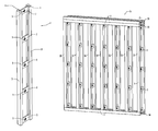
FIG. 9 is an axonometric representation of a reduced thermal bridge wall assembly according to embodiments of the present disclosure; and
FIG. 10 is two-dimensional cross-sectional view depicting an embodiment of the present disclosure assembled within a wall section.
DETAILED DESCRIPTION
In the following description, reference is made to the accompanying drawings that form a part thereof, and in which is shown by way of illustration specific exemplary embodiments in which the embodiments of the disclosure may be practiced. These embodiments are described in sufficient detail to enable those skilled in the art to practice the disclosure, and it is to be understood that modifications to the various disclosed embodiments may be made, and other embodiments may be utilized, without departing from the spirit and scope of the disclosure. The following detailed description is, therefore, not to be taken in a limiting sense.
One method of reducing energy usage in a building is to reduce conductive heat loss from thermal bridging through the exterior wall structure of the building. Thermal bridging may be reduced through the use of construction materials having relatively high thermal resistance, by reducing the cross-sectional area of wall structures, or through a combination of both. In the context of this disclosure, a cross-sectional area is defined as the intersection of the building component or element in question with a plane that is parallel to a wall or similar construction into which the building component or element may be integrated. As such, within the context of this disclosure, a cross-sectional area may typically be roughly perpendicular to a direction of heat transfer conduction through the construction component. One objective of the low thermal bridge building components is to reduce thermal bridging and resulting energy loss through these components in buildings. The low thermal bridge components disclosed herein may significantly reduce conductive heat transfer and thus reduce the energy required to heat or cool a residential, commercial, or other type of building.
Low thermal bridge studs, plates, and other building components disclosed herein may allow builders to use standard construction techniques. Construction time and procedures may be similar to conventional wall framing using standard construction techniques with dimensional lumber. Construction costs may also be similar to standard construction costs using dimensional lumber. Walls constructed using building components and methods disclosed herein can be thick and thus allow for thick insulation having high R-values, while still being light weight and using less wood for framing compared to conventional techniques.
As shown in FIG. 1, the low thermal bridge building component 1 according to embodiments of the present disclosure is arranged similar to an I-beam, having roughly parallel opposing flanges 3 and a web 2 that connect the flanges 3. In embodiments, web 2 comprises a thin cross-section relative to flanges 3 to reduce conductive heat transfer from one flange 3 to the other. In embodiments, web 2 is perforated with holes 5 and/or comprises non-continuous web pieces, as shown in FIG. 1, to further reduce the cross-sectional area and resultant conductive heat transfer.
A standard 8 foot long dimensional lumber stud has a cross-sectional area of approximately 144 square inches (1.5 inches×96 inches). The low thermal bridge building component 1 has a much smaller cross-sectional area than a traditional standard dimensional lumber stud. In the embodiment depicted in FIG. 1, there are five webs 2 that are approximately 4 inches tall and ½ inch wide. As a result, the lateral cross-sectional area across the web 2 is 10 square inches (4 inches×½ inch×5 webs). This area is roughly 6.94% of the cross-sectional area of a standard dimensional lumber stud having the same height. In addition, if a 2-inch diameter hole 5 is added to each piece of the web 2, the cross-sectional area of the web 2 is reduced to 5 square inches while still maintaining the same web-to-flange glue joint 4 length. This area is roughly 3.47% of the cross-sectional area of a standard stud. This reduced cross-sectional area may greatly reduce thermal bridging and the resultant heat loss or gain. Embodiments that are made with less wood may, as a result, comprise less material volume than conventional building components. As used herein, “material volume” refers to the volume of material of a building component without counting any internal voids. For example, traditional dimensional lumber that is 1.5 inches wide, 96 inches tall, and 10 inches thick may comprise a material volume of approximately 1440 cubic inches (96 inches×1.5 inches×10 inches). As an additional example, the embodiment depicted in FIG. 1 having flanges that are 1.5 inches wide, 1 inch thick and 96 inches tall and webs that are 4 inches tall, ½ inches thick, and 8 inches wide may comprise a material volume of approximately 368 cubic inches (96 inches×1.5 inches×1 inch×2 flanges+4 inches×½ inch×8 inches×5 webs). As an additional example, the embodiment depicted in FIG. 1 having flanges that are 3.5 inches wide, 1 inch thick and 96 inches tall and webs that are 4 inches tall, ½ inches thick, and 9.25 inches wide may comprise a material volume of approximately 764.5 cubic inches (96 inches×3.5 inches×1 inch×2 flanges+4 inches×½ inch×9.25 inches×5 webs). A target material volume amount may be selectively achieved by varying one or more of the component dimensions.
Embodiments of the present disclosure having less material volume than similarly-sized traditional dimensional lumber may, as a result, weigh less than similarly-sized traditional dimensional lumber. Table 1 illustrates typical weights for various dimensional lumber beams.
TABLE 1
Dimensions for conventional dimensional lumber.
Overall Overall Weight per
Nominal Width Thickness 8 feet of length
2x6 1.5 inches 5.5 inches 14.73 pounds
2x8 1.5 inches 7.25 inches 19.42 pounds
2x10 1.5 inches 9.25 inches 24.78 pounds
2x12 1.5 inches 11.25 inches 30.13 pounds
In comparison, similarly-sized embodiments of the present disclosure may weigh substantially less than typical dimensional lumber beams. Table 2 depicts measured weights for building components according to the present disclosure.
TABLE 2
Dimensions for embodiments of the present disclosure.
Overall Overall Weight per
Nominal Width Thickness 8 feet of length
2x6 1.5 inches 5.5 inches 13.06 pounds
2x8 1.5 inches 7.25 inches 13.46 pounds
2x10 1.5 inches 9.25 inches 13.92 pounds
2x12 1.5 inches 11.25 inches 14.38 pounds
The conductive heat transfer through a wall stud is directly proportional to the cross-sectional area of the stud. If the cross-sectional area is reduced, the heat transfer may be reduced proportionally. Therefore, the embodiment depicted in FIG. 1 may reduce conductive heat transfer to approximately 6.94% without a hole 5 in the web 2 or approximately 3.47% with a hole 5 in the web 2 compared to conductive heat transfer through a standard dimensional lumber stud. Embodiments of the building component 1 comprise a longitudinal length of 8 feet (the longitudinal direction being defined in the direction of greatest size of the building component). In alternative embodiments, the length of building component 1 may be selectively designed according to specific circumstances and building criteria. Because there is essentially no air movement in the wall cavities between studs, thermal conduction through wall studs and other components may be assumed to be the primary driver of heat transfer through wall assemblies. (In a typical installation, there is little to no air movement in the cavities in part because of the insulation that is installed within the wall.)
In a typical installation, building component 1 may be installed within a wall with each flange 3 abutted and affixed to a wall surface. For example, one flange 3 may be affixed to drywall panels forming an interior wall. That flange 3 would accordingly comprise an inner-facing flange 3 and the flange 3 surface which abuts the drywall panels may comprise a peripheral inner-facing surface. Likewise, the other flange 3 may be affixed to exterior wall panels at the peripheral outer-facing surface of that flange 3. However, it is to be understood that the peripheral inner-facing surface and the peripheral outer-facing surface of building component 1 might not necessarily be affixed to an interior or exterior wall, respectively.
FIG. 2 illustrates an embodiment of a flange member 3. Embodiments of the studs, plates, and like building components of the present disclosure may be constructed by cutting a groove 9 in the flange members 3 to accommodate the placement of the web pieces 2. FIG. 3 illustrates an embodiment of a web piece 2. Web pieces 2 may be glued and/or fastened in place in the groove 9 using means known in the art to maintain the integrity and strength of the assembly and create the I-beam-like configuration. The webs 2 and flanges 3 are sized to attain the desired dimensions and strength of the assembled building component 1. The length of the web 2 can be selectively sized to accommodate the desired wall thickness and also the desired wall insulation thickness. The length of the flanges 3 can also be varied to accommodate various wall heights and/or lengths.
In embodiments of the present disclosure, the webs 2 and flanges 5 may be constructed using dimensional lumber or engineered materials such as oriented strand board (OSB), plywood, laminated veneer lumber (LVL), laminated strand lumber (LSL), rim-board, glued laminated lumber (glulam), like materials, or combinations thereof. Use of engineered materials may provide increased dimensional stability in comparison to dimensional lumber. Dimensional stability may also be improved in components where dimensional lumber is used because the movement of one flange 3 can be counteracted by the other due to the webs 2 that connect the flanges 3. Alternatively, the flanges 3, webs 2, or both may be manufactured from other materials such as aluminum, steel, or plastic or plastic composites. The web may also be made of honeycomb, rigid foam insulation, or other insulating material to reduce the thermal bridge between the flanges 3. As will be understood by one of ordinary skill in the art having the benefit of this disclosure, other materials of manufacture may be suitable for the web 2 and flanges 3. Such materials fall under the scope of this disclosure.
Dimensional lumber used for framing buildings may be prone to cupping, bowing, twisting, and crowning. This dimensional instability may cause the dimensional lumber to be more difficult to frame for doors and windows because it may be difficult to keep the door and window rough openings square, level, plumb, and flat for window mounting and door hanging. Embodiments of low thermal bridge building components according to the present disclosure may be more dimensionally stable, which could allow for easier and better installation of doors and windows. This advantage may be especially pronounced where engineered wood products are used for the flanges 3 of the building components. The use of flanges 3 that are wider than dimensional lumber may also provide a wider nailing surface, which may result in fewer nail misses during construction.
Webs 2 may be cut from dimensional lumber or from the types of engineered wood products mentioned above. For embodiments that comprise holes 5 in the webs 2, such holes can be drilled, punched, or made using other methods. These holes 5 may further reduce the heat transfer through the web 2 by reducing the cross-sectional area of each web 2 without significant reduction of the strength of the web 2 or the web-to-flange joint. Web 2 thickness and width can be selected to meet the structural requirements of the assembly and the insulation requirements of the building's walls. The flanges 3 can be made from dimensional lumber or engineered wood products. The groove 9 can be cut using a dado blade on a table saw or other suitable milling technique. The cross-sectional dimensions of the flanges 3 are selected to meet structural and rigidity requirements of the assembly. For example, buildings that are constructed in areas with high snow loads may need larger flanges 3 to meet structural buckling requirements. The strength and/or rigidity of the flanges 3 may be based on their area moment of inertia. For a rectangular lateral cross-section of a flange member 3, the mathematical formula for the area moment of inertia is:
I = b × d 3 12
where:
I is the moment of inertia of the flange member 3;
b is the side-to-side thickness of the flange member 3; and
d is the depth of the flange member 3 in the direction that a force is applied.
This equation shows that a small increase in the depth can greatly increase the strength and rigidity of the flange 3 when it is subjected to bending or column loading because the depth is cubed in the equation. The flange 3 dimensions may also be selected to allow for fastening of sheet material (e.g. OSB or the like) and/or siding to the outside flange 3 and materials such as sheetrock or wood products to the inside flange 3. Use of wide flanges 3 may reduce the chance for nails or screws to miss the studs during attachment of sheeting products.
Building component embodiments according to the present disclosure may be constructed by applying glue to grooves 9 and then forcing the webs 2 and flanges 3 together using clamps or other suitable means, thereby forming joints 4 between web 2 and flanges 3. The width of groove 9 may be selected to allow for a forced fit with the webs 2 so that the assembly retains its integrity after the clamping force is removed. Assembly fixtures may be used during assembly to maintain the dimensional integrity of the low thermal bridge building component 1 (in other words, maintaining the component flat, straight, etc.). In alternative embodiments, the webs 2 are nailed and/or stapled to the flanges 3. In addition or alternatively, the webs 2 are placed in mortised holes that are a partial or full depth of the flanges 3.
FIG. 4 depicts an embodiment of a low thermal bridge building component 10 according to the present disclosure. As illustrated in FIG. 4, embodiments achieve relatively low thermal bridging by incorporating numerous holes 13 in a continuous web 12. This approach may allow for field cutting the assembly 10 to attain the desired length without regard for the placement of multiple web pieces. However, the web-to-flange joints 14 of this embodiment may be significantly stronger because the joints 14 are continuous along the flanges 11 and web 12. The fabrication approach may be similar to that used for the embodiment depicted in FIG. 1.
As an example, if 2 inch diameter holes 13 are spaced to leave ½ inch of web 12 material between the holes, the resulting cross-sectional area of the assembly is approximately 10 square inches for an 8 foot long stud. Accordingly, such a building component has a cross-sectional area that is approximately 6.94% of a standard dimensional lumber stud and thus will have only approximately 6.94% of the conductive heat transfer of a dimensional lumber stud. Various hole 13 sizes and/or spacing may achieve different results.
Referring to FIG. 5, an embodiment of a building component 15 according to the present disclosure comprises OSB, dimensional lumber, or other material that is laminated together to form a low thermal bridge configuration. The web 17 has multiple holes 18 to further reduce thermal bridging. The building component 15 can be fabricated using standard sawing and milling techniques. The components can be glued together or otherwise fastened to attain the desired structural integrity. Web 17 length can be selected to achieve the desired building wall thickness. The thickness of the four flange pieces 16 can be selected to achieve the desired stiffness and strength. The overall flange 16 thickness may generally be thicker than the thickness of standard lumber studs and plates because of the I-beam-like configuration. The glue joints 19 may provide relatively high shear strength to the building component 15, which may allow it to accommodate high lateral wind loads in a building wall assembly.
FIG. 6 depicts an embodiment of a building component 20 according to the present disclosure. Embodiments of building component 20 comprise a solid OSB, LSL, rim board, or similar material pressing. This configuration has a relatively thin web 47 at its middle and multiple holes 22 to reduce thermal bridging. Embodiments of building component 20 have a web 47 comprising a curved surface with a curve radius of approximately four inches. Embodiments of building component 20 have a web 47 comprising a thickness at its middle that is less than one-fourth of its thickness at its edges. Alternatively, web 47 dimensions may be selectively varied to meet specific circumstances such as cost, weight, strength, and/or thermal bridging requirements. Alternative embodiments are constructed using plywood, LVL, LSL, or glulam materials. One possible benefit of embodiments of building component 20 is that a “net final” shape may be achieved and there may be no need for further fabrication. Building component 20 may be constructed using techniques similar to those currently used to make LSL studs and/or rim boards. Shaped rollers may be used to form the I-beam-like configuration and curved web 47. Building component 20 may be manufactured by unevenly building up wood chips prior to pressing to create the varying thickness of web 47.
FIG. 7 depicts an embodiment of a building component 23 comprising flanges 24 made of dimensional lumber, OSB, plywood, LVL, LSL, rim board, or other like material and web 25 that is made of honeycomb or rigid foam insulation (for example, polystyrene, polyisocyanurate, and/or polyurethane). The web 25 provides the low thermal bridge due to its relatively high R-value compared to the flanges 24. Building component 23 may comprise an I-beam shaped configuration due to the flanges 24 being slightly thicker than web 25. As depicted in FIG. 7, web 25 is bracketed by C-shaped flanges 24. In embodiments, web 25 is roughly the same thickness as the flanges 24. In embodiments, web 25 comprises a single, integral piece of honeycomb or rigid foam insulation material. Such an embodiment of web 25 comprises no separate side pieces or end pieces. Some embodiments include no other material besides the material of web 25 bridging the flanges 24. The web 25 may be glued to the flanges 24. Embodiments comprise hole 26 passing through web 25 to accommodate routing of electrical or instrumentation wiring or to allow for routing of plumbing. The width of web 25 may be selected to attain the wall thickness and R-value desired. In embodiments, the relatively wide building component 23 may exhibit higher thermal resistance than wall cavities insulated with cellulose or fiberglass. The thickness and width of the flanges 24 may be selected to achieve the desired stiffness and strength. The web 25 and flange 24 can be fabricated using standard construction techniques and tools. Embodiments of building component 23 may result in joints with high shear strength because of the relatively large glue area. Embodiments of the present disclosure may also provide for substantial sound attenuation.
Embodiments comprising a web 25 that is made of honeycomb or rigid foam may exhibit superior thermal insulating properties relative to traditional building components. For example, one embodiment comprises two wood flanges, each flange having a thickness of approximately 1.5 inches, and a rigid polystyrene web having a thickness of 2.5 inches. A polystyrene web that is 2.5 inches thick may have an R-value of approximately 12.5, using a commonly-accepted R-value of polystyrene of 5/inch. The flanges may have a cumulative R-value of approximately 3.75, using a commonly-accepted R-value of wood of 1.25/inch. Thus, such a building component embodiment may have a total R-value of approximately 16.25. As another example, an embodiment comprises two wood flanges, each flange having a thickness of approximately 1.5 inches, and a rigid polyisocyanurate web having a thickness of 8.25 inches. A polyisocyanurate web that is 8.25 inches thick may have an R-value of approximately 53.63, using a commonly-accepted R-value of polyisocyanurate of 6.5/inch. The flanges may have a cumulative R-value of approximately 3.75. Thus, such a building component embodiment may have a total R-value of approximately 57.38. By varying the thickness of the web and/or flanges or by varying the materials of the web and/or flanges, components having other R-values are conceivable.
An alternate fabrication approach is to spray foam insulation between two flanges 24 that are held flat and parallel by fixtures. This approach may be accomplished without glue or fasteners, as the spray foam may adhere directly to the flanges 24. The continuous web 25 may allow the building component 23 to be cut to any length without compromising the structural integrity of the assembly. Long component 23 lengths may be achieved using embodiments of building component 23.
In operation, embodiments of building components of the present disclosure may be used as studs, plates, headers, or like components in wall assemblies in construction. Building components disclosed herein may take the place of traditional dimensional lumber or engineered wood studs, plates, and/or headers. Referring now to FIGS. 8A, 8B, and 8C, a wall assembly 27 is depicted using low thermal bridge studs 28 and plates 29, 30 as disclosed herein. FIGS. 8A and 8B depict side views of wall assembly 27 and FIG. 8C depicts a top view of wall assembly 27. The plates 29, 30 can be nailed or otherwise attached to the studs 28 to form the wall assembly 27. Two top plates 29 may be used in this wall assembly 27 to increase strength and support the roof. This configuration may reduce thermal bridging in comparison to traditional wall assemblies. The studs 28 and plates 29, 30 may be sized to accommodate the structural needs of the building or structure. They may also be sized to attain the desired wall thickness and/or to meet the insulation thickness requirements of the building and building codes. The wall assembly 27 may be suitable for insulation that is blown-in (e.g., urethane, cellulose, and fiberglass). It may be relatively easy to increase the wall thickness by increasing the width of webs 2, which may have little effect on cost or weight of the assembled wall 27. The studs 28, plates 29, 30, or other building components of a wall assembly may comprise various embodiments of building components having flanges and webs as disclosed herein.
FIG. 9 is an axonometric drawing of a wall assembly 31 comprising building components studs 32 and plates 33, 34. Each stud and plate 33, 34 comprises two opposing flanges 3 and multiple web pieces 2. FIG. 9 illustrates that electrical and instrument wiring may be routed within the wall assembly 31 through spaces in each component 32, 33, 34. Where climates allow, plumbing may also be routed through the wall 31. Because the webs 2 provide communication between adjacent studs 32, wiring and plumbing could be passed through the walls 37 without drilling access holes through solid studs, as is currently done in typical construction. This feature may significantly reduce the amount of labor exerted during construction. The studs 32 and plates 33, 34 could also be used in interior walls to allow easy routing of wiring and plumbing. The wall assembly 31 may have significantly less mass than a traditional wall assembly.
FIG. 10 is a two-dimensional cross-sectional view depicting various building components 36, 37, 44 of the present disclosure assembled within a wall section 35. Spaces between webs 2 can be used to route wiring and plumbing without the need to drill holes as is the case when traditional dimensional lumber is used to construct wall assemblies. Insulation 41 may fill in any voids between webs 2 and/or between studs 37 to mitigate air movement within the wall section 35. Wall surface panels 39, for example rigid board insulation, may be attached to outer-facing surfaces of building components 36, 37, 44 as is typically practiced in the art. Vertical battens 40 may be installed on wall surface 39. Siding 41 or other outer covering may then be installed on the exterior of wall assembly 35. Sheetrock 42 or similar interior panels may be installed in inner-facing surfaces of components 36, 37, 44.
As one of ordinary skill having the benefit of this disclosure would understand, embodiments presented herein may provide certain useful advantages over traditional building components and techniques. Such benefits may include reduced conductive heat transfer through building walls and thus reduced energy consumption. Another benefit may include a greater degree of design selection flexibility, including the ability to selectively vary wall thickness by selectively altering the size of the webs. Additionally, a thicker wall may permit an increased amount of insulation material to be placed therein. Walls constructed with embodiments of the present disclosure may be lighter in weight than similar sized walls constructed with traditional studs and other components. Lighter walls may be less costly to transport to a building site.
Walls constructed with embodiments of the present disclosure may also use less lumber than similar-sized walls that are constructed using dimensional lumber or other traditional building components. Low thermal-bridging building components of the present disclosure can simplify the construction of highly-insulated buildings and thereby result in reduced construction and material costs.
Although the present disclosure is described in terms of certain preferred embodiments, other embodiments will be apparent to those of ordinary skill in the art, given the benefit of this disclosure, including embodiments that do not provide all of the benefits and features set forth herein, which are also within the scope of this disclosure. It is to be understood that other embodiments may be utilized, without departing from the spirit and scope of the present disclosure.

Claims (16)

What is claimed is:
1. A low thermal bridge building component comprising:
at least two flanges, each one of the at least two flanges comprising an outer surface, and
a web joining the at least two flanges and maintaining the outer surfaces of the at least two flanges in a roughly parallel configuration;
wherein:
the web has an R-value between 12 and 54 and
the web comprises a perforation.
2. The low thermal bridge building component of claim 1, wherein the at least two flanges are manufactured from lumber.
3. The low thermal bridge building component of claim 1, wherein the at least two flanges are manufactured from a material selected from the group consisting of aluminum, steel, plastic, insulation, and plastic composites.
4. The low thermal bridge building component of claim 1, wherein the web comprises a honeycomb or rigid foam material.
5. The low thermal bridge building component of claim 1, wherein the low thermal bridge building component has an approximate overall thickness of 3.5 inches, 5.5 inches, 7.25 inches, 9.25 inches, or 11.25 inches, wherein the overall thickness is defined as a measurement between outer opposing surfaces of the at least two flanges.
6. The low thermal bridge building component of claim 5, wherein:
the low thermal bridge building component has an approximate overall thickness of 5.5 inches and
the low thermal bridge building component has a weight of less than 14 pounds per 8 foot length.
7. The low thermal bridge building component of claim 5, wherein:
the low thermal bridge building component has an approximate overall thickness of 7.25 inches and
the low thermal bridge building component has a weight of less than 19 pounds per 8 foot length.
8. The low thermal bridge building component of claim 5, wherein:
the low thermal bridge building component has an approximate overall thickness of 9.25 inches and
the low thermal bridge building component has a weight of less than 24 pounds per 8 foot length.
9. The low thermal bridge building component of claim 5, wherein:
the low thermal bridge building component has an approximate overall thickness of 11.25 inches and
the low thermal bridge building component has a weight of less than 30 pounds per 8 foot length.
10. The low thermal bridge building component of claim 1, wherein the building component is selected from the group consisting of a wall plate and a wall stud.
11. The low thermal bridge building component of claim 1, wherein the low thermal bridge building component has an R-value between 16 and 58.
12. The low thermal bridge building component of claim 1, wherein each one of the at least two flanges comprises a C-shape.
13. A low thermal bridge building component comprising:
at least two opposing flanges and
a web joining the at least two flanges and maintaining the at least two flanges in a roughly parallel configuration;
wherein:
the web comprises a single, integral web member;
the web member is the only member that joins the at least two flanges; and
the web has an R-value between 12 and 54.
14. The low thermal bridge building component of claim 13, wherein the web comprises a honeycomb or rigid foam material.
15. The low thermal bridge building component of claim 13, wherein the low thermal bridge building component has an R-value between 16 and 58.
16. The low thermal bridge building component of claim 13, wherein each one of the at least two flanges comprises a C-shape.
US14/104,734 2012-02-28 2013-12-12 Low thermal bridge building components Expired - Fee Related US8820034B1 (en)

Priority Applications (1)

Application Number Priority Date Filing Date Title
US14/104,734 US8820034B1 (en) 2012-02-28 2013-12-12 Low thermal bridge building components

Applications Claiming Priority (3)

Application Number Priority Date Filing Date Title
US201261603945P 2012-02-28 2012-02-28
US13/778,113 US8640429B1 (en) 2012-02-28 2013-02-26 Low thermal bridge building components
US14/104,734 US8820034B1 (en) 2012-02-28 2013-12-12 Low thermal bridge building components

Related Parent Applications (1)

Application Number Title Priority Date Filing Date
US13/778,113 Continuation-In-Part US8640429B1 (en) 2012-02-28 2013-02-26 Low thermal bridge building components

Publications (1)

Publication Number Publication Date
US8820034B1 true US8820034B1 (en) 2014-09-02

Family

ID=51399814

Family Applications (1)

Application Number Title Priority Date Filing Date
US14/104,734 Expired - Fee Related US8820034B1 (en) 2012-02-28 2013-12-12 Low thermal bridge building components

Country Status (1)

Country Link
US (1) US8820034B1 (en)

Cited By (21)

* Cited by examiner, † Cited by third party
Publication number Priority date Publication date Assignee Title
US20130305643A1 (en) * 2012-05-18 2013-11-21 Nexgen Framing Solutions LLC Structural insulated panel framing system
US20140202100A1 (en) * 2011-08-04 2014-07-24 Tomislav Prlic Insulated wall module
US20150137670A1 (en) * 2013-11-18 2015-05-21 Heatcraft Refrigeration Products Llc Insulated Foam Panels for Refrigerated Display Cases
CN106295063A (en) * 2016-08-24 2017-01-04 大连都市发展设计有限公司 Building node equivalent face heat transfer coefficient calculating method
US20170138041A1 (en) * 2015-11-18 2017-05-18 Glenalmond Timber Company Limited Single Leaf Separating Wall
USD796063S1 (en) * 2015-11-04 2017-08-29 Pinkwood Ltd. I-joist
US10253499B2 (en) 2015-08-28 2019-04-09 Australian Engineered Solutions Pty Ltd Structural building element
US20190203463A1 (en) * 2018-01-04 2019-07-04 Jon PUES Energy wall stud member and construction system
US20200018057A1 (en) * 2018-07-13 2020-01-16 David L. Harmon Architectural Construction Technique
US10731332B1 (en) * 2019-08-28 2020-08-04 Roosevelt Energy, Llc Composite reinforced wood stud for residential and commercial buildings
US11066826B2 (en) 2018-08-21 2021-07-20 John David Wright Insulatable, insulative framework apparatus and methods of making and using same
USD936242S1 (en) 2019-08-28 2021-11-16 Roosevelt Energy, Inc. Composite reinforced wood stud for buildings
USD938618S1 (en) 2019-11-26 2021-12-14 Roosevelt Energy, Inc. Reinforced pinned dowel composite stud for buildings
USD941496S1 (en) 2019-11-14 2022-01-18 Roosevelt Energy, Inc. Stud for buildings
USD941498S1 (en) 2019-11-26 2022-01-18 Roosevelt Energy, Inc. Composite t-shaped in-line dowell reinforced wood stud for buildings
USD942049S1 (en) 2019-11-14 2022-01-25 Roosevelt Energy, Inc. L-shaped composite reinforced wood stud for buildings
US11255084B2 (en) 2019-06-10 2022-02-22 Roosevelt Energy, Inc. Thermal break wood columns, buttresses and headers with rigid insulation
USD950105S1 (en) * 2019-12-17 2022-04-26 Pinkwood Ltd. I-joist
USD994903S1 (en) * 2020-11-30 2023-08-08 Super Stud Building Products, Inc. Joist
US20240110442A1 (en) * 2017-05-10 2024-04-04 Werner Co. Ceiling ladder, deep step and method
USD1033679S1 (en) 2021-01-29 2024-07-02 Roosevelt Energy, Inc. Stud for buildings

Citations (14)

* Cited by examiner, † Cited by third party
Publication number Priority date Publication date Assignee Title
US4336678A (en) * 1978-07-24 1982-06-29 Peters Dierk D I-Beam truss structure
US4578909A (en) * 1982-12-30 1986-04-01 Enercept, Inc. Insulated building construction
US5617693A (en) * 1996-01-22 1997-04-08 Hefner; Richard P. Prefabricated wall trusses for super-insulated walls
US5625996A (en) * 1995-08-28 1997-05-06 Bechtel; Friend K. Fire resistant wood box beam
US5678381A (en) * 1994-11-25 1997-10-21 Denadel; Duane G. Insulated beam
US5966894A (en) * 1997-12-02 1999-10-19 Crump, Jr.; Preston L. Modular insulated framing beam assembly
US6276110B1 (en) * 1997-11-11 2001-08-21 Sodra Timber Ab Stud for a timber wall
US6412249B1 (en) * 1995-10-17 2002-07-02 Boyer Building Products, Inc. Wall stud
US6460310B1 (en) * 2000-09-26 2002-10-08 Graftech Inc. Composite I-beam having improved properties
US6701690B2 (en) * 2001-07-17 2004-03-09 Guildo Deschenes I-shaped wooden beam
US6772572B2 (en) * 2002-05-09 2004-08-10 Riley Beloit Corporation Fabricated OSB stud
US20080134619A1 (en) * 2006-12-06 2008-06-12 Georgia-Pacific Wood Products Llc I-beam joist having openings formed therein for mechanical access
US20100293889A1 (en) * 2009-05-22 2010-11-25 Deboef Jr Duane R Alternative I-Stud
US7905073B2 (en) * 2002-03-18 2011-03-15 Global Building Systems, Inc. Method and apparatus for assembling strong, lightweight thermal panel and insulated building structure

Patent Citations (14)

* Cited by examiner, † Cited by third party
Publication number Priority date Publication date Assignee Title
US4336678A (en) * 1978-07-24 1982-06-29 Peters Dierk D I-Beam truss structure
US4578909A (en) * 1982-12-30 1986-04-01 Enercept, Inc. Insulated building construction
US5678381A (en) * 1994-11-25 1997-10-21 Denadel; Duane G. Insulated beam
US5625996A (en) * 1995-08-28 1997-05-06 Bechtel; Friend K. Fire resistant wood box beam
US6412249B1 (en) * 1995-10-17 2002-07-02 Boyer Building Products, Inc. Wall stud
US5617693A (en) * 1996-01-22 1997-04-08 Hefner; Richard P. Prefabricated wall trusses for super-insulated walls
US6276110B1 (en) * 1997-11-11 2001-08-21 Sodra Timber Ab Stud for a timber wall
US5966894A (en) * 1997-12-02 1999-10-19 Crump, Jr.; Preston L. Modular insulated framing beam assembly
US6460310B1 (en) * 2000-09-26 2002-10-08 Graftech Inc. Composite I-beam having improved properties
US6701690B2 (en) * 2001-07-17 2004-03-09 Guildo Deschenes I-shaped wooden beam
US7905073B2 (en) * 2002-03-18 2011-03-15 Global Building Systems, Inc. Method and apparatus for assembling strong, lightweight thermal panel and insulated building structure
US6772572B2 (en) * 2002-05-09 2004-08-10 Riley Beloit Corporation Fabricated OSB stud
US20080134619A1 (en) * 2006-12-06 2008-06-12 Georgia-Pacific Wood Products Llc I-beam joist having openings formed therein for mechanical access
US20100293889A1 (en) * 2009-05-22 2010-11-25 Deboef Jr Duane R Alternative I-Stud

Cited By (30)

* Cited by examiner, † Cited by third party
Publication number Priority date Publication date Assignee Title
US20140202100A1 (en) * 2011-08-04 2014-07-24 Tomislav Prlic Insulated wall module
US10760270B2 (en) 2012-05-18 2020-09-01 Nexgen Framing Solutions LLC Structural insulated panel framing system
US9624666B2 (en) * 2012-05-18 2017-04-18 Nexgen Framing Solutions LLC Structural insulated panel framing system
US20130305643A1 (en) * 2012-05-18 2013-11-21 Nexgen Framing Solutions LLC Structural insulated panel framing system
US9687089B2 (en) * 2013-11-18 2017-06-27 Heatcraft Refrigeration Products Llc Insulated foam panels for refrigerated display cases
US20150137670A1 (en) * 2013-11-18 2015-05-21 Heatcraft Refrigeration Products Llc Insulated Foam Panels for Refrigerated Display Cases
US10253499B2 (en) 2015-08-28 2019-04-09 Australian Engineered Solutions Pty Ltd Structural building element
USD796063S1 (en) * 2015-11-04 2017-08-29 Pinkwood Ltd. I-joist
USD872875S1 (en) * 2015-11-04 2020-01-14 Pinkwood Ltd. I-joist
US20170138041A1 (en) * 2015-11-18 2017-05-18 Glenalmond Timber Company Limited Single Leaf Separating Wall
US10392797B2 (en) * 2015-11-18 2019-08-27 Glenalmond Timber Company Limited Single leaf separating wall
CN106295063B (en) * 2016-08-24 2019-03-22 大连都市发展设计有限公司 Building node equivalent face heat transfer coefficient calculation method
CN106295063A (en) * 2016-08-24 2017-01-04 大连都市发展设计有限公司 Building node equivalent face heat transfer coefficient calculating method
US20240110442A1 (en) * 2017-05-10 2024-04-04 Werner Co. Ceiling ladder, deep step and method
US10612235B2 (en) * 2018-01-04 2020-04-07 Jon PUES Energy wall stud member and construction system
US20190203463A1 (en) * 2018-01-04 2019-07-04 Jon PUES Energy wall stud member and construction system
US20200018057A1 (en) * 2018-07-13 2020-01-16 David L. Harmon Architectural Construction Technique
US10968619B2 (en) * 2018-07-13 2021-04-06 David L. Harmon Architectural construction technique
US11808031B2 (en) 2018-08-21 2023-11-07 J. David Wright LLC Insulatable, insulative framework apparatus and methods of making and using same
US11066826B2 (en) 2018-08-21 2021-07-20 John David Wright Insulatable, insulative framework apparatus and methods of making and using same
US11255084B2 (en) 2019-06-10 2022-02-22 Roosevelt Energy, Inc. Thermal break wood columns, buttresses and headers with rigid insulation
US10731332B1 (en) * 2019-08-28 2020-08-04 Roosevelt Energy, Llc Composite reinforced wood stud for residential and commercial buildings
USD936242S1 (en) 2019-08-28 2021-11-16 Roosevelt Energy, Inc. Composite reinforced wood stud for buildings
USD941496S1 (en) 2019-11-14 2022-01-18 Roosevelt Energy, Inc. Stud for buildings
USD942049S1 (en) 2019-11-14 2022-01-25 Roosevelt Energy, Inc. L-shaped composite reinforced wood stud for buildings
USD941498S1 (en) 2019-11-26 2022-01-18 Roosevelt Energy, Inc. Composite t-shaped in-line dowell reinforced wood stud for buildings
USD938618S1 (en) 2019-11-26 2021-12-14 Roosevelt Energy, Inc. Reinforced pinned dowel composite stud for buildings
USD950105S1 (en) * 2019-12-17 2022-04-26 Pinkwood Ltd. I-joist
USD994903S1 (en) * 2020-11-30 2023-08-08 Super Stud Building Products, Inc. Joist
USD1033679S1 (en) 2021-01-29 2024-07-02 Roosevelt Energy, Inc. Stud for buildings

Similar Documents

Publication Publication Date Title
US8820034B1 (en) Low thermal bridge building components
US8640429B1 (en) Low thermal bridge building components
US10273689B2 (en) Panel and method for fabricating, installing and utilizing a panel
US10024057B2 (en) Construction panel system and methods of assembly thereof
US9783985B2 (en) Thermal break wood stud with rigid insulation with non-metal fasteners and wall framing system
US20070227095A1 (en) Separated Member Wood Framing
AU2010283967B2 (en) Building system
EP2316624A2 (en) Multi-layer wood panel
EP2273024B1 (en) Building element and roof construction
CA2746305A1 (en) High strength light-framed wall structure
US10731341B2 (en) Floor assemblies, methods for their manufacture, and the use of such assemblies in a building
US11255084B2 (en) Thermal break wood columns, buttresses and headers with rigid insulation
US20120291384A1 (en) Insulated wall panel apparatuses, systems, and methods
US11840836B2 (en) Structural wall panel system
WO2023102178A1 (en) Insulated engineered structural member
CN210238892U (en) Orthogonal glued wood floor with composite structure
US9725902B1 (en) Panel and method for fabricating, installing and utilizing a panel
RU165747U1 (en) BUILDING CONSTRUCTION BUILDING DESIGN
GB2465845A (en) Building panel having wooden I-beam edge
GB2399577A (en) Wooden beam with corrugated paper or cardboard filling
US20050102962A1 (en) Timber block
US20090260310A1 (en) Method and system for providing an insulative wall structure
EP1811097B1 (en) Building element
RU2344246C2 (en) Three-layer construction panel
CA2792344A1 (en) Ventilated structural panels and method of construction with ventilated structural panels

Legal Events

Date Code Title Description
AS Assignment

Owner name: THERMAL FRAMING, LLC., IDAHO

Free format text: ASSIGNMENT OF ASSIGNORS INTEREST;ASSIGNORS:WATTS, KENNETH DONALD;WATTS, DONALD GENE MCINTYRE;SIGNING DATES FROM 20130221 TO 20130225;REEL/FRAME:032165/0124

STCF Information on status: patent grant

Free format text: PATENTED CASE

FEPP Fee payment procedure

Free format text: MAINTENANCE FEE REMINDER MAILED (ORIGINAL EVENT CODE: REM.)

FEPP Fee payment procedure

Free format text: SURCHARGE FOR LATE PAYMENT, MICRO ENTITY (ORIGINAL EVENT CODE: M3554); ENTITY STATUS OF PATENT OWNER: MICROENTITY

MAFP Maintenance fee payment

Free format text: PAYMENT OF MAINTENANCE FEE, 4TH YEAR, MICRO ENTITY (ORIGINAL EVENT CODE: M3551); ENTITY STATUS OF PATENT OWNER: MICROENTITY

Year of fee payment: 4

FEPP Fee payment procedure

Free format text: MAINTENANCE FEE REMINDER MAILED (ORIGINAL EVENT CODE: REM.); ENTITY STATUS OF PATENT OWNER: MICROENTITY

LAPS Lapse for failure to pay maintenance fees

Free format text: PATENT EXPIRED FOR FAILURE TO PAY MAINTENANCE FEES (ORIGINAL EVENT CODE: EXP.); ENTITY STATUS OF PATENT OWNER: MICROENTITY

STCH Information on status: patent discontinuation

Free format text: PATENT EXPIRED DUE TO NONPAYMENT OF MAINTENANCE FEES UNDER 37 CFR 1.362

FP Lapsed due to failure to pay maintenance fee

Effective date: 20220902