US8791372B2 - Reducing impedance discontinuity in packages - Google Patents
Reducing impedance discontinuity in packages Download PDFInfo
- Publication number
- US8791372B2 US8791372B2 US13/426,892 US201213426892A US8791372B2 US 8791372 B2 US8791372 B2 US 8791372B2 US 201213426892 A US201213426892 A US 201213426892A US 8791372 B2 US8791372 B2 US 8791372B2
- Authority
- US
- United States
- Prior art keywords
- pth
- pths
- layer
- magnetic material
- vias
- Prior art date
- Legal status (The legal status is an assumption and is not a legal conclusion. Google has not performed a legal analysis and makes no representation as to the accuracy of the status listed.)
- Active
Links
- PXHVJJICTQNCMI-UHFFFAOYSA-N Nickel Chemical compound [Ni] PXHVJJICTQNCMI-UHFFFAOYSA-N 0.000 claims abstract description 20
- 229910052759 nickel Inorganic materials 0.000 claims abstract description 10
- 239000007769 metal material Substances 0.000 claims abstract description 6
- 230000003247 decreasing effect Effects 0.000 claims abstract description 5
- 239000002184 metal Substances 0.000 claims description 35
- 229910052751 metal Inorganic materials 0.000 claims description 35
- 238000000034 method Methods 0.000 claims description 22
- 239000000696 magnetic material Substances 0.000 claims description 14
- RYGMFSIKBFXOCR-UHFFFAOYSA-N Copper Chemical group [Cu] RYGMFSIKBFXOCR-UHFFFAOYSA-N 0.000 claims description 13
- 229910052802 copper Inorganic materials 0.000 claims description 13
- 239000010949 copper Substances 0.000 claims description 13
- 239000011347 resin Substances 0.000 claims description 13
- 229920005989 resin Polymers 0.000 claims description 13
- 230000001965 increasing effect Effects 0.000 claims description 12
- 239000002318 adhesion promoter Substances 0.000 claims description 2
- 238000000623 plasma-assisted chemical vapour deposition Methods 0.000 claims description 2
- 238000004544 sputter deposition Methods 0.000 claims description 2
- 230000008878 coupling Effects 0.000 claims 1
- 238000010168 coupling process Methods 0.000 claims 1
- 238000005859 coupling reaction Methods 0.000 claims 1
- 239000010410 layer Substances 0.000 abstract description 68
- 239000012792 core layer Substances 0.000 abstract description 3
- 238000000576 coating method Methods 0.000 description 15
- 239000011248 coating agent Substances 0.000 description 13
- HHXNVASVVVNNDG-UHFFFAOYSA-N 1,2,3,4,5-pentachloro-6-(2,3,6-trichlorophenyl)benzene Chemical compound ClC1=CC=C(Cl)C(C=2C(=C(Cl)C(Cl)=C(Cl)C=2Cl)Cl)=C1Cl HHXNVASVVVNNDG-UHFFFAOYSA-N 0.000 description 7
- 239000003989 dielectric material Substances 0.000 description 6
- 230000007423 decrease Effects 0.000 description 4
- 238000000151 deposition Methods 0.000 description 3
- 230000008021 deposition Effects 0.000 description 3
- RKUAZJIXKHPFRK-UHFFFAOYSA-N 1,3,5-trichloro-2-(2,4-dichlorophenyl)benzene Chemical compound ClC1=CC(Cl)=CC=C1C1=C(Cl)C=C(Cl)C=C1Cl RKUAZJIXKHPFRK-UHFFFAOYSA-N 0.000 description 2
- 239000004251 Ammonium lactate Substances 0.000 description 2
- 230000005540 biological transmission Effects 0.000 description 2
- 238000010586 diagram Methods 0.000 description 2
- 230000001939 inductive effect Effects 0.000 description 2
- 239000000463 material Substances 0.000 description 2
- 238000003491 array Methods 0.000 description 1
- 230000015556 catabolic process Effects 0.000 description 1
- 230000001413 cellular effect Effects 0.000 description 1
- 230000001010 compromised effect Effects 0.000 description 1
- 238000006731 degradation reaction Methods 0.000 description 1
- 230000006866 deterioration Effects 0.000 description 1
- 230000003292 diminished effect Effects 0.000 description 1
- 238000007598 dipping method Methods 0.000 description 1
- 238000005553 drilling Methods 0.000 description 1
- 238000004100 electronic packaging Methods 0.000 description 1
- 239000003999 initiator Substances 0.000 description 1
- 238000004519 manufacturing process Methods 0.000 description 1
- 238000001465 metallisation Methods 0.000 description 1
- 238000012986 modification Methods 0.000 description 1
- 230000004048 modification Effects 0.000 description 1
- 230000006855 networking Effects 0.000 description 1
- 238000004806 packaging method and process Methods 0.000 description 1
- 230000001902 propagating effect Effects 0.000 description 1
Images


Classifications
-
- H—ELECTRICITY
- H05—ELECTRIC TECHNIQUES NOT OTHERWISE PROVIDED FOR
- H05K—PRINTED CIRCUITS; CASINGS OR CONSTRUCTIONAL DETAILS OF ELECTRIC APPARATUS; MANUFACTURE OF ASSEMBLAGES OF ELECTRICAL COMPONENTS
- H05K1/00—Printed circuits
- H05K1/02—Details
- H05K1/11—Printed elements for providing electric connections to or between printed circuits
- H05K1/115—Via connections; Lands around holes or via connections
-
- H—ELECTRICITY
- H05—ELECTRIC TECHNIQUES NOT OTHERWISE PROVIDED FOR
- H05K—PRINTED CIRCUITS; CASINGS OR CONSTRUCTIONAL DETAILS OF ELECTRIC APPARATUS; MANUFACTURE OF ASSEMBLAGES OF ELECTRICAL COMPONENTS
- H05K1/00—Printed circuits
- H05K1/02—Details
- H05K1/0213—Electrical arrangements not otherwise provided for
- H05K1/0216—Reduction of cross-talk, noise or electromagnetic interference
- H05K1/023—Reduction of cross-talk, noise or electromagnetic interference using auxiliary mounted passive components or auxiliary substances
- H05K1/0233—Filters, inductors or a magnetic substance
-
- H—ELECTRICITY
- H01—ELECTRIC ELEMENTS
- H01F—MAGNETS; INDUCTANCES; TRANSFORMERS; SELECTION OF MATERIALS FOR THEIR MAGNETIC PROPERTIES
- H01F17/00—Fixed inductances of the signal type
- H01F17/0006—Printed inductances
- H01F17/0013—Printed inductances with stacked layers
-
- H—ELECTRICITY
- H05—ELECTRIC TECHNIQUES NOT OTHERWISE PROVIDED FOR
- H05K—PRINTED CIRCUITS; CASINGS OR CONSTRUCTIONAL DETAILS OF ELECTRIC APPARATUS; MANUFACTURE OF ASSEMBLAGES OF ELECTRICAL COMPONENTS
- H05K3/00—Apparatus or processes for manufacturing printed circuits
- H05K3/46—Manufacturing multilayer circuits
- H05K3/4602—Manufacturing multilayer circuits characterized by a special circuit board as base or central core whereon additional circuit layers are built or additional circuit boards are laminated
-
- H—ELECTRICITY
- H05—ELECTRIC TECHNIQUES NOT OTHERWISE PROVIDED FOR
- H05K—PRINTED CIRCUITS; CASINGS OR CONSTRUCTIONAL DETAILS OF ELECTRIC APPARATUS; MANUFACTURE OF ASSEMBLAGES OF ELECTRICAL COMPONENTS
- H05K1/00—Printed circuits
- H05K1/02—Details
- H05K1/11—Printed elements for providing electric connections to or between printed circuits
- H05K1/111—Pads for surface mounting, e.g. lay-out
- H05K1/112—Pads for surface mounting, e.g. lay-out directly combined with via connections
-
- H—ELECTRICITY
- H05—ELECTRIC TECHNIQUES NOT OTHERWISE PROVIDED FOR
- H05K—PRINTED CIRCUITS; CASINGS OR CONSTRUCTIONAL DETAILS OF ELECTRIC APPARATUS; MANUFACTURE OF ASSEMBLAGES OF ELECTRICAL COMPONENTS
- H05K2201/00—Indexing scheme relating to printed circuits covered by H05K1/00
- H05K2201/08—Magnetic details
- H05K2201/083—Magnetic materials
- H05K2201/086—Magnetic materials for inductive purposes, e.g. printed inductor with ferrite core
-
- H—ELECTRICITY
- H05—ELECTRIC TECHNIQUES NOT OTHERWISE PROVIDED FOR
- H05K—PRINTED CIRCUITS; CASINGS OR CONSTRUCTIONAL DETAILS OF ELECTRIC APPARATUS; MANUFACTURE OF ASSEMBLAGES OF ELECTRICAL COMPONENTS
- H05K2201/00—Indexing scheme relating to printed circuits covered by H05K1/00
- H05K2201/09—Shape and layout
- H05K2201/09209—Shape and layout details of conductors
- H05K2201/095—Conductive through-holes or vias
- H05K2201/09536—Buried plated through-holes, i.e. plated through-holes formed in a core before lamination
-
- H—ELECTRICITY
- H05—ELECTRIC TECHNIQUES NOT OTHERWISE PROVIDED FOR
- H05K—PRINTED CIRCUITS; CASINGS OR CONSTRUCTIONAL DETAILS OF ELECTRIC APPARATUS; MANUFACTURE OF ASSEMBLAGES OF ELECTRICAL COMPONENTS
- H05K2201/00—Indexing scheme relating to printed circuits covered by H05K1/00
- H05K2201/09—Shape and layout
- H05K2201/09209—Shape and layout details of conductors
- H05K2201/095—Conductive through-holes or vias
- H05K2201/096—Vertically aligned vias, holes or stacked vias
-
- H—ELECTRICITY
- H05—ELECTRIC TECHNIQUES NOT OTHERWISE PROVIDED FOR
- H05K—PRINTED CIRCUITS; CASINGS OR CONSTRUCTIONAL DETAILS OF ELECTRIC APPARATUS; MANUFACTURE OF ASSEMBLAGES OF ELECTRICAL COMPONENTS
- H05K3/00—Apparatus or processes for manufacturing printed circuits
- H05K3/40—Forming printed elements for providing electric connections to or between printed circuits
- H05K3/42—Plated through-holes or plated via connections
-
- Y—GENERAL TAGGING OF NEW TECHNOLOGICAL DEVELOPMENTS; GENERAL TAGGING OF CROSS-SECTIONAL TECHNOLOGIES SPANNING OVER SEVERAL SECTIONS OF THE IPC; TECHNICAL SUBJECTS COVERED BY FORMER USPC CROSS-REFERENCE ART COLLECTIONS [XRACs] AND DIGESTS
- Y10—TECHNICAL SUBJECTS COVERED BY FORMER USPC
- Y10T—TECHNICAL SUBJECTS COVERED BY FORMER US CLASSIFICATION
- Y10T29/00—Metal working
- Y10T29/49—Method of mechanical manufacture
- Y10T29/49002—Electrical device making
- Y10T29/49117—Conductor or circuit manufacturing
- Y10T29/49124—On flat or curved insulated base, e.g., printed circuit, etc.
- Y10T29/49155—Manufacturing circuit on or in base
- Y10T29/49165—Manufacturing circuit on or in base by forming conductive walled aperture in base
Definitions
- the present invention generally relates to electronic circuits and in particular to reducing impedance discontinuity in the packaging of electronic circuits.
- PTHs plated through holes
- BGAs ball grid arrays
- PTHs plated through holes
- PTH vias are imbedded in the core of a printed circuit board comprising a core layer, a plurality of buildup layers, a plurality of micro-vias, and a plurality of traces. Traces electrically interconnect each of the micro-vias to PTH vias, forming an electrically conductive path.
- PTH vias are fabricated with magnetic metal coatings to reduce distortion of high speed signals.
- Electronic packages output high speed signals that are compromised due to excess capacitance in PTHs.
- holes are drilled into the core dielectric material of the printed circuit board.
- a magnetic metal coating is added to the walls of PTHs to reduce the impedance discontinuity of the electronic package.
- Deposition of a metal material, such as nickel, is followed by coating the metal material with copper. After coating the walls of the PTH via, resin may be deposited into the via.
- impedance discontinuity is reduced by utilizing a PTH via connected to the trace of a printed circuit board.
- the PTH via coated with the magnetic metal coating, is connected to the trace from the copper layer of the PTH via.
- the magnetic coating material increases internal and external inductance in the electronic package by changing the magnetic environment.
- PTH vias with only a copper layer contain excess capacitance. Increasing the inductance of the PTH via utilizing the magnetic layer compensates for the excess capacitance without compromising the structure of the printed circuit board.
- impedance discontinuity is further reduced by utilizing one or more PTH vias that are not connected to the trace of a printed circuit board.
- a magnetic metal layer is deposited on the PTH vias, followed by the copper coating and resin deposition.
- one or more PTH vias are imbedded in the dielectric core of the printed circuit board without connecting to a trace. Additional PTH vias with metal coatings and no trace connection further increases inductance; thereby, reducing impedance discontinuity.
- FIG. 1 is a cross-sectional view of a printed circuit board with a plated through hole coated with a magnetic material according to one embodiment of the invention
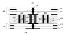
- FIG. 2 is a cross-sectional view of a printed circuit board with a plurality of plated through holes coated with a magnetic material, in accordance with one embodiment of the invention
- FIG. 3 is a schematic diagram of the process flow of creating plated through holes with a magnetic layer according to one embodiment of the invention.
- FIG. 4 is an illustration of a PTH via coated with a magnetic layer according to one embodiment of the invention.
- PTHs plated through holes
- PTH vias are imbedded in the core of a printed circuit board comprising a core layer, a plurality of buildup layers, a plurality of micro-vias, and a plurality of traces. Traces electrically interconnect each of the micro-vias to PTH vias, forming an electrically conductive path.
- Multiple layer (multi-layer) printed circuit board (PCB) 100 of FIG. 1 comprises the primary functional components found in an electrical package for transmitting high speed signals.
- Interconnected PTH via 140 is created within core dielectric 108 disposed (i.e., positioned) between upper planar conductive layer 128 (L1, L2, L3) and lower planar conductive layer 129 (L4, L5, L6), which layers may run in a substantially parallel direction relative to each other.
- Lower planar conductive layer 129 also comprises ball grid array (BGA) 118 .
- BGA ball grid array
- Functional pads 110 are arranged on upper planar conductive layer 128 and lower planar conductive layer 129 . Functional pads 110 are electrically connected to a conductive pattern (i.e. a signal trace, a ground or voltage, or a passive device, etc.).
- a conductive pattern i.e. a signal trace, a ground or voltage, or a passive device, etc.
- trace vias 114 and trace pads 116 are connected with interconnected PTH via 140 through via trace pad 112 .
- Via trace pad 112 connects to copper layer 104 , which is between magnetic metal layer 106 .
- Magnetic metal layer 106 and copper layer 104 enclose resin 102 .
- interconnected PTH via 140 surrounded by magnetic metal layer 106 decreases impedance discontinuity by increasing inductance.
- Magnetic metal layer 106 modifies the internal and external magnetic environment of multi-layer PCB 100 by increasing the internal and external inductance of interconnected PTH via 140 .
- interconnected PTH via 140 forms an electrically conductive path with trace vias 114 and trace pads 116 through via trace pad 112 .
- Trace vias 114 and trace pads 112 are arranged within each separate upper planar layers 128 and lower planar layers 129 forming a stable structure for controlling the impedance of interconnected PTH via 140 . Preserving all layers of upper planar layers 128 and lower planar layers 129 avoids deterioration of plane integrity, maintains trace length for signal routing, and retains mechanical strength of multi-layer PCB 100 .
- FIG. 2 is a cross-sectional view of a printed circuit board with a plurality of plated through holes that are modified with a magnetic metal coating. Similar to FIG. 1 , FIG. 2 comprises multi-layer PCB 200 . Multi-layer PCB 200 is also composed of the primary functional components found in an electrical package for transmitting high speed signals. Interconnected PTH via 240 is created within core dielectric 208 , which is disposed (positioned) between upper planar conductive layer 228 (L1, L2, L3) and lower planar conductive layer 229 (L4, L5, L6). Lower planar conductive layer 229 also comprises ball grid array (BGA) 218 .
- BGA ball grid array
- Functional pads 210 are arranged on upper planar conductive layer 228 and lower planar conductive layer 229 . Functional pads 210 are electrically connected to a conductive pattern (i.e. a signal trace, a ground or voltage, or a passive device, etc.).
- a conductive pattern i.e. a signal trace, a ground or voltage, or a passive device, etc.
- trace vias 214 and trace pads 216 are connected with interconnected PTH 240 through via trace pad 212 .
- Via trace pad 212 connects to copper layer 204 which is inside of magnetic metal layer 206 .
- Magnetic metal layer 206 and copper layer 204 enclose resin 202 .
- Non-connected PTH vias 230 are also coated with magnetic metal layer 206 and copper layer 204 .
- Magnetic metal layer 206 and copper layer 204 , of non-connected PTH vias 230 enclose resin 202 .
- impedance discontinuity of a high speed signal within multi-layer PCB 200 is further improved by imbedding non-connected PTH vias 230 within PCB 200 .
- Magnetic metal coating 206 of non-connected PTH vias 230 increase external conductance, compensating for excess capacitance within PTH vias 230 , without forming redundant electrically conductive paths.
- the increased magnetic metal contributed by non-connected PTH vias 230 modifies the magnetic environment of multi-layer PCB 200 and does not add additional trace length or jeopardize the structure of multi-layer PCB 200 .
- FIG. 3 is a schematic diagram of the process flow of creating PTHs with a magnetic metal coating for use as PTH vias in a PCB.
- Schematic 300 comprises five views: View A 320 , View B 322 , View C 324 , View D 326 , and View E 328 .
- the process flow begins at View A 320 with core dielectric 308 , which is the base material utilized for fabricating PCB 200 having one or more PTHs 340 .
- core dielectric 308 is the base material utilized for fabricating PCB 200 having one or more PTHs 340 .
- PTHs 340 are drilled to a certain diameter, for example approximately 120 micrometers.
- view C 324 the walls of PTH 340 are coated with magnetic metal layer 306 .
- One or more microns of magnetic metal layer 306 may be deposited on the walls of PTHs 340 . Multiple methods may be utilized to deposit magnetic metal layer 306 on the walls of PTHs 340 , for example: plasma enhanced chemical vapor deposition, sputtering, dipping, and spin-on may be utilized for the metallization step. After coating the walls of PTHs 340 with magnetic metal layer 306 , copper layer 304 is deposited over magnetic metal layer 306 , in view D 326 . Resin 302 is deposited into PTH 340 in view E 328 .
- magnetic metal layer 306 may be nickel.
- the nickel layer is deposited on the walls of the dielectric. If necessary, an adhesion promoter is utilized to insure adhesion of the nickel to the walls of the dielectric material.
- the thickness of magnetic metal layer 306 deposited on the walls of the dielectric material in view C 324 is greater than the skin depth, thereby increasing the effectiveness of magnetic coating.
- FIG. 4 is a flow chart illustrating a method by which the above processes of the illustrative embodiments are completed. Although the methods illustrated in FIG. 4 may be described with reference to components shown in FIGS. 1-3 , it should be understood that this is merely for convenience and alternative components and/or configurations thereof can be employed when implementing the various methods.
- the process of FIG. 4 begins at initiator block 400 .
- a dielectric material is prepared for drilling PTHs. PTHs are drilled through the core dielectric material, at step 402 .
- the core dielectric material is between two or more planar conductive layers.
- a thin magnetic metal layer such as nickel, is plated on the walls of the drilled PTHs.
- a copper layer is deposited onto the layer of magnetic metal layer.
- step 408 A determination is made at step 408 , as to whether to fill the PTHs with resin. If resin is to be utilized, the PTHs are filled with resin at step 410 , then the process continues to step 412 . If resin is not utilized the process proceeds to step 412 . At step 412 , the conventional process for completing the electronic package is completed. The process ends at step 414 .
Landscapes
- Engineering & Computer Science (AREA)
- Microelectronics & Electronic Packaging (AREA)
- Physics & Mathematics (AREA)
- Electromagnetism (AREA)
- Manufacturing & Machinery (AREA)
- Power Engineering (AREA)
- Production Of Multi-Layered Print Wiring Board (AREA)
Abstract
Description
Claims (16)
Priority Applications (1)
| Application Number | Priority Date | Filing Date | Title |
|---|---|---|---|
| US13/426,892 US8791372B2 (en) | 2007-11-19 | 2012-03-22 | Reducing impedance discontinuity in packages |
Applications Claiming Priority (2)
| Application Number | Priority Date | Filing Date | Title |
|---|---|---|---|
| US11/942,061 US8440917B2 (en) | 2007-11-19 | 2007-11-19 | Method and apparatus to reduce impedance discontinuity in packages |
| US13/426,892 US8791372B2 (en) | 2007-11-19 | 2012-03-22 | Reducing impedance discontinuity in packages |
Related Parent Applications (1)
| Application Number | Title | Priority Date | Filing Date |
|---|---|---|---|
| US11/942,061 Division US8440917B2 (en) | 2007-11-19 | 2007-11-19 | Method and apparatus to reduce impedance discontinuity in packages |
Publications (2)
| Publication Number | Publication Date |
|---|---|
| US20130075148A1 US20130075148A1 (en) | 2013-03-28 |
| US8791372B2 true US8791372B2 (en) | 2014-07-29 |
Family
ID=40640742
Family Applications (2)
| Application Number | Title | Priority Date | Filing Date |
|---|---|---|---|
| US11/942,061 Expired - Fee Related US8440917B2 (en) | 2007-11-19 | 2007-11-19 | Method and apparatus to reduce impedance discontinuity in packages |
| US13/426,892 Active US8791372B2 (en) | 2007-11-19 | 2012-03-22 | Reducing impedance discontinuity in packages |
Family Applications Before (1)
| Application Number | Title | Priority Date | Filing Date |
|---|---|---|---|
| US11/942,061 Expired - Fee Related US8440917B2 (en) | 2007-11-19 | 2007-11-19 | Method and apparatus to reduce impedance discontinuity in packages |
Country Status (1)
| Country | Link |
|---|---|
| US (2) | US8440917B2 (en) |
Cited By (2)
| Publication number | Priority date | Publication date | Assignee | Title |
|---|---|---|---|---|
| US20140174809A1 (en) * | 2012-12-20 | 2014-06-26 | Samsung Electro-Mechanics Co., Ltd. | Circuit board and method of manufacturing the same |
| US20170223836A1 (en) * | 2014-11-07 | 2017-08-03 | Murata Manufacturing Co., Ltd. | Connector module |
Families Citing this family (20)
| Publication number | Priority date | Publication date | Assignee | Title |
|---|---|---|---|---|
| US8440517B2 (en) * | 2010-10-13 | 2013-05-14 | Taiwan Semiconductor Manufacturing Company, Ltd. | FinFET and method of fabricating the same |
| US9144150B2 (en) * | 2012-04-20 | 2015-09-22 | Xilinx, Inc. | Conductor structure with integrated via element |
| US9082870B2 (en) | 2013-03-13 | 2015-07-14 | Taiwan Semiconductor Manufacturing Company, Ltd. | Methods and apparatus of packaging semiconductor devices |
| WO2015006660A2 (en) * | 2013-07-12 | 2015-01-15 | The University Of Florida Reearch Foundation, Inc. | Low ohmic loss radial superlattice conductors |
| US10141107B2 (en) * | 2013-10-10 | 2018-11-27 | Analog Devices, Inc. | Miniature planar transformer |
| US9959967B2 (en) | 2014-05-15 | 2018-05-01 | Analog Devices, Inc. | Magnetic devices and methods for manufacture using flex circuits |
| US10650937B2 (en) * | 2015-12-28 | 2020-05-12 | The University Of Florida Research Foundation, Inc | Low OHMIC loss superlattice conductors |
| US9807867B2 (en) * | 2016-02-04 | 2017-10-31 | Taiwan Semiconductor Manufacturing Co., Ltd. | Interconnect structure and method of manufacturing the same |
| US10910305B2 (en) * | 2016-12-30 | 2021-02-02 | Intel Corporation | Microelectronic devices designed with capacitive and enhanced inductive bumps |
| CN107835565B (en) * | 2017-10-24 | 2020-01-14 | Oppo广东移动通信有限公司 | Printed circuit board and mobile terminal |
| US11251113B2 (en) * | 2017-12-27 | 2022-02-15 | Intel Corporation | Methods of embedding magnetic structures in substrates |
| CN109980400B (en) * | 2017-12-28 | 2021-07-23 | 泰科电子(上海)有限公司 | Connector with a locking member |
| CN109982504B (en) * | 2017-12-28 | 2021-06-25 | 泰科电子(上海)有限公司 | Circuit board and board card |
| CN111010797A (en) * | 2018-10-08 | 2020-04-14 | 中兴通讯股份有限公司 | Circuit board, equipment and via hole forming method |
| GB201816833D0 (en) * | 2018-10-16 | 2018-11-28 | Univ College Cork National Univ Of Ireland Cork | A vertical magnetic structure for integrated power conversion |
| US11622448B2 (en) * | 2019-07-08 | 2023-04-04 | Intel Corporation | Sandwich-molded cores for high-inductance architectures |
| JP7512111B2 (en) | 2020-07-29 | 2024-07-08 | 新光電気工業株式会社 | Wiring board and manufacturing method thereof |
| JP2022032233A (en) * | 2020-08-11 | 2022-02-25 | 新光電気工業株式会社 | Wiring board and manufacturing method thereof |
| JP7562431B2 (en) | 2021-01-07 | 2024-10-07 | 新光電気工業株式会社 | Wiring board and method for manufacturing the same |
| JP7543631B2 (en) * | 2021-04-28 | 2024-09-03 | 新光電気工業株式会社 | Wiring board and manufacturing method thereof |
Citations (8)
| Publication number | Priority date | Publication date | Assignee | Title |
|---|---|---|---|---|
| US4131516A (en) * | 1977-07-21 | 1978-12-26 | International Business Machines Corporation | Method of making metal filled via holes in ceramic circuit boards |
| US5309632A (en) * | 1988-03-28 | 1994-05-10 | Hitachi Chemical Co., Ltd. | Process for producing printed wiring board |
| US5438167A (en) * | 1992-09-24 | 1995-08-01 | Hughes Aircraft Company | Ferrimagnetic vias within multi-layer 3-dimensional structures/substrates |
| US5587885A (en) * | 1994-05-18 | 1996-12-24 | Dell Usa, L.P. | Mechanical printed circuit board/laminated multi chip module interconnect apparatus |
| US20050064707A1 (en) * | 2003-09-23 | 2005-03-24 | Nishant Sinha | Process and integration scheme for fabricating conductive components, through-vias and semiconductor components including conductive through-wafer vias |
| US20050126818A1 (en) * | 2003-12-16 | 2005-06-16 | Toshifumi Kojima | Multilayer wiring board |
| US20060131611A1 (en) * | 2004-12-17 | 2006-06-22 | Heiko Kaluzni | Multi-layer printed circuit board comprising a through connection for high frequency applications |
| US20070169959A1 (en) * | 2006-01-24 | 2007-07-26 | International Business Machines Corporation | Microelectronic device with mixed dielectric |
Family Cites Families (6)
| Publication number | Priority date | Publication date | Assignee | Title |
|---|---|---|---|---|
| US6570102B2 (en) * | 2000-02-01 | 2003-05-27 | International Business Machines Corporation | Structure for high speed printed wiring boards with multiple differential impedance-controlled layer |
| JP2001257471A (en) * | 2000-03-10 | 2001-09-21 | Ngk Insulators Ltd | Multilayer wiring board and manufacturing method thereof |
| WO2001099480A2 (en) * | 2000-06-19 | 2001-12-27 | 3M Innovative Properties Company | Printed circuit board having inductive vias |
| US6498381B2 (en) * | 2001-02-22 | 2002-12-24 | Tru-Si Technologies, Inc. | Semiconductor structures having multiple conductive layers in an opening, and methods for fabricating same |
| US7129567B2 (en) * | 2004-08-31 | 2006-10-31 | Micron Technology, Inc. | Substrate, semiconductor die, multichip module, and system including a via structure comprising a plurality of conductive elements |
| TWI278268B (en) * | 2006-02-23 | 2007-04-01 | Via Tech Inc | Arrangement of non-signal through vias and wiring board applying the same |
-
2007
- 2007-11-19 US US11/942,061 patent/US8440917B2/en not_active Expired - Fee Related
-
2012
- 2012-03-22 US US13/426,892 patent/US8791372B2/en active Active
Patent Citations (8)
| Publication number | Priority date | Publication date | Assignee | Title |
|---|---|---|---|---|
| US4131516A (en) * | 1977-07-21 | 1978-12-26 | International Business Machines Corporation | Method of making metal filled via holes in ceramic circuit boards |
| US5309632A (en) * | 1988-03-28 | 1994-05-10 | Hitachi Chemical Co., Ltd. | Process for producing printed wiring board |
| US5438167A (en) * | 1992-09-24 | 1995-08-01 | Hughes Aircraft Company | Ferrimagnetic vias within multi-layer 3-dimensional structures/substrates |
| US5587885A (en) * | 1994-05-18 | 1996-12-24 | Dell Usa, L.P. | Mechanical printed circuit board/laminated multi chip module interconnect apparatus |
| US20050064707A1 (en) * | 2003-09-23 | 2005-03-24 | Nishant Sinha | Process and integration scheme for fabricating conductive components, through-vias and semiconductor components including conductive through-wafer vias |
| US20050126818A1 (en) * | 2003-12-16 | 2005-06-16 | Toshifumi Kojima | Multilayer wiring board |
| US20060131611A1 (en) * | 2004-12-17 | 2006-06-22 | Heiko Kaluzni | Multi-layer printed circuit board comprising a through connection for high frequency applications |
| US20070169959A1 (en) * | 2006-01-24 | 2007-07-26 | International Business Machines Corporation | Microelectronic device with mixed dielectric |
Cited By (4)
| Publication number | Priority date | Publication date | Assignee | Title |
|---|---|---|---|---|
| US20140174809A1 (en) * | 2012-12-20 | 2014-06-26 | Samsung Electro-Mechanics Co., Ltd. | Circuit board and method of manufacturing the same |
| US9035196B2 (en) * | 2012-12-20 | 2015-05-19 | Samsung Electro-Mechanics Co., Ltd. | Circuit board and method of manufacturing the same |
| US20170223836A1 (en) * | 2014-11-07 | 2017-08-03 | Murata Manufacturing Co., Ltd. | Connector module |
| US10004144B2 (en) * | 2014-11-07 | 2018-06-19 | Murata Manufacturing Co., Ltd. | Connector module |
Also Published As
| Publication number | Publication date |
|---|---|
| US20130075148A1 (en) | 2013-03-28 |
| US20090126983A1 (en) | 2009-05-21 |
| US8440917B2 (en) | 2013-05-14 |
Similar Documents
| Publication | Publication Date | Title |
|---|---|---|
| US8791372B2 (en) | Reducing impedance discontinuity in packages | |
| US10375838B2 (en) | Sleeved coaxial printed circuit board vias | |
| US7168957B2 (en) | Via providing multiple electrically conductive paths | |
| US7781889B2 (en) | Shielded via | |
| US7435911B2 (en) | Printed circuit board including embedded capacitor and method of fabricating same | |
| US7385470B2 (en) | Technique for reducing via capacitance | |
| CN103188886B (en) | A kind of printed circuit board and preparation method thereof | |
| US20120180312A1 (en) | Core via for chip package and interconnect | |
| US10201085B2 (en) | Methods of forming blind vias for printed circuit boards | |
| CN105307382A (en) | Printed circuit board and method of manufacturing the same | |
| JP5172341B2 (en) | Substrate assembly, multilayer circuit board assembly, ball grid array package, electronic assembly, method of minimizing parasitic capacitance in substrate assembly, and method of manufacturing substrate assembly | |
| US20180317327A1 (en) | Methods of forming segmented vias for printed circuit boards | |
| US20130105987A1 (en) | Laminate interconnect having a coaxial via structure | |
| US7754980B2 (en) | Substrate with multilayer plated through hole and method for forming the multilayer plated through hole | |
| CN103887272B (en) | Electronic module and its manufacture method | |
| US20040238938A1 (en) | Substrate method and apparatus | |
| US20110061917A1 (en) | Laminated substrate for an integrated circuit bga package and printed circuit boards | |
| CN104604341A (en) | Wiring substrate and production method therefor | |
| US20210378092A1 (en) | Carrier board structure with an increased core-layer trace area and method for manufacturing same | |
| KR100509974B1 (en) | Method for manufacturing PCB | |
| US9433091B1 (en) | Customizing connections of conductors of a printed circuit board | |
| CN118338526A (en) | Wiring substrate | |
| CN118338525A (en) | Wiring substrate | |
| CN113225917A (en) | Method for manufacturing circuit board with back drilling hole | |
| KR20060108902A (en) | Mulit-layer board and method for fabricating via hole thereof |
Legal Events
| Date | Code | Title | Description |
|---|---|---|---|
| STCF | Information on status: patent grant |
Free format text: PATENTED CASE |
|
| AS | Assignment |
Owner name: GLOBALFOUNDRIES U.S. 2 LLC, NEW YORK Free format text: ASSIGNMENT OF ASSIGNORS INTEREST;ASSIGNOR:INTERNATIONAL BUSINESS MACHINES CORPORATION;REEL/FRAME:036550/0001 Effective date: 20150629 |
|
| AS | Assignment |
Owner name: GLOBALFOUNDRIES INC., CAYMAN ISLANDS Free format text: ASSIGNMENT OF ASSIGNORS INTEREST;ASSIGNORS:GLOBALFOUNDRIES U.S. 2 LLC;GLOBALFOUNDRIES U.S. INC.;REEL/FRAME:036779/0001 Effective date: 20150910 |
|
| MAFP | Maintenance fee payment |
Free format text: PAYMENT OF MAINTENANCE FEE, 4TH YEAR, LARGE ENTITY (ORIGINAL EVENT CODE: M1551) Year of fee payment: 4 |
|
| AS | Assignment |
Owner name: WILMINGTON TRUST, NATIONAL ASSOCIATION, DELAWARE Free format text: SECURITY AGREEMENT;ASSIGNOR:GLOBALFOUNDRIES INC.;REEL/FRAME:049490/0001 Effective date: 20181127 |
|
| AS | Assignment |
Owner name: GLOBALFOUNDRIES INC., CAYMAN ISLANDS Free format text: RELEASE BY SECURED PARTY;ASSIGNOR:WILMINGTON TRUST, NATIONAL ASSOCIATION;REEL/FRAME:054479/0842 Effective date: 20200410 Owner name: TAIWAN SEMICONDUCTOR MANUFACTURING CO., LTD., TAIWAN Free format text: ASSIGNMENT OF ASSIGNORS INTEREST;ASSIGNOR:GLOBALFOUNDRIES INC.;REEL/FRAME:054482/0862 Effective date: 20200515 |
|
| AS | Assignment |
Owner name: GLOBALFOUNDRIES INC., CAYMAN ISLANDS Free format text: RELEASE BY SECURED PARTY;ASSIGNOR:WILMINGTON TRUST, NATIONAL ASSOCIATION;REEL/FRAME:054636/0001 Effective date: 20201117 |
|
| MAFP | Maintenance fee payment |
Free format text: PAYMENT OF MAINTENANCE FEE, 8TH YEAR, LARGE ENTITY (ORIGINAL EVENT CODE: M1552); ENTITY STATUS OF PATENT OWNER: LARGE ENTITY Year of fee payment: 8 |