US8783283B2 - Heating device for valve to prevent internal accumulation of condensate - Google Patents
Heating device for valve to prevent internal accumulation of condensate Download PDFInfo
- Publication number
- US8783283B2 US8783283B2 US13/362,692 US201213362692A US8783283B2 US 8783283 B2 US8783283 B2 US 8783283B2 US 201213362692 A US201213362692 A US 201213362692A US 8783283 B2 US8783283 B2 US 8783283B2
- Authority
- US
- United States
- Prior art keywords
- valve
- valve body
- heating device
- piston
- temperature
- Prior art date
- Legal status (The legal status is an assumption and is not a legal conclusion. Google has not performed a legal analysis and makes no representation as to the accuracy of the status listed.)
- Active, expires
Links
Images


Classifications
-
- F—MECHANICAL ENGINEERING; LIGHTING; HEATING; WEAPONS; BLASTING
- F16—ENGINEERING ELEMENTS AND UNITS; GENERAL MEASURES FOR PRODUCING AND MAINTAINING EFFECTIVE FUNCTIONING OF MACHINES OR INSTALLATIONS; THERMAL INSULATION IN GENERAL
- F16K—VALVES; TAPS; COCKS; ACTUATING-FLOATS; DEVICES FOR VENTING OR AERATING
- F16K49/00—Means in or on valves for heating or cooling
- F16K49/002—Electric heating means
-
- F—MECHANICAL ENGINEERING; LIGHTING; HEATING; WEAPONS; BLASTING
- F01—MACHINES OR ENGINES IN GENERAL; ENGINE PLANTS IN GENERAL; STEAM ENGINES
- F01B—MACHINES OR ENGINES, IN GENERAL OR OF POSITIVE-DISPLACEMENT TYPE, e.g. STEAM ENGINES
- F01B29/00—Machines or engines with pertinent characteristics other than those provided for in preceding main groups
- F01B29/08—Reciprocating-piston machines or engines not otherwise provided for
- F01B29/10—Engines
-
- F—MECHANICAL ENGINEERING; LIGHTING; HEATING; WEAPONS; BLASTING
- F02—COMBUSTION ENGINES; HOT-GAS OR COMBUSTION-PRODUCT ENGINE PLANTS
- F02B—INTERNAL-COMBUSTION PISTON ENGINES; COMBUSTION ENGINES IN GENERAL
- F02B47/00—Methods of operating engines involving adding non-fuel substances or anti-knock agents to combustion air, fuel, or fuel-air mixtures of engines
- F02B47/02—Methods of operating engines involving adding non-fuel substances or anti-knock agents to combustion air, fuel, or fuel-air mixtures of engines the substances being water or steam
-
- F—MECHANICAL ENGINEERING; LIGHTING; HEATING; WEAPONS; BLASTING
- F16—ENGINEERING ELEMENTS AND UNITS; GENERAL MEASURES FOR PRODUCING AND MAINTAINING EFFECTIVE FUNCTIONING OF MACHINES OR INSTALLATIONS; THERMAL INSULATION IN GENERAL
- F16K—VALVES; TAPS; COCKS; ACTUATING-FLOATS; DEVICES FOR VENTING OR AERATING
- F16K1/00—Lift valves or globe valves, i.e. cut-off apparatus with closure members having at least a component of their opening and closing motion perpendicular to the closing faces
- F16K1/32—Details
-
- F—MECHANICAL ENGINEERING; LIGHTING; HEATING; WEAPONS; BLASTING
- F16—ENGINEERING ELEMENTS AND UNITS; GENERAL MEASURES FOR PRODUCING AND MAINTAINING EFFECTIVE FUNCTIONING OF MACHINES OR INSTALLATIONS; THERMAL INSULATION IN GENERAL
- F16K—VALVES; TAPS; COCKS; ACTUATING-FLOATS; DEVICES FOR VENTING OR AERATING
- F16K27/00—Construction of housing; Use of materials therefor
- F16K27/02—Construction of housing; Use of materials therefor of lift valves
-
- Y—GENERAL TAGGING OF NEW TECHNOLOGICAL DEVELOPMENTS; GENERAL TAGGING OF CROSS-SECTIONAL TECHNOLOGIES SPANNING OVER SEVERAL SECTIONS OF THE IPC; TECHNICAL SUBJECTS COVERED BY FORMER USPC CROSS-REFERENCE ART COLLECTIONS [XRACs] AND DIGESTS
- Y10—TECHNICAL SUBJECTS COVERED BY FORMER USPC
- Y10T—TECHNICAL SUBJECTS COVERED BY FORMER US CLASSIFICATION
- Y10T137/00—Fluid handling
- Y10T137/0318—Processes
-
- Y—GENERAL TAGGING OF NEW TECHNOLOGICAL DEVELOPMENTS; GENERAL TAGGING OF CROSS-SECTIONAL TECHNOLOGIES SPANNING OVER SEVERAL SECTIONS OF THE IPC; TECHNICAL SUBJECTS COVERED BY FORMER USPC CROSS-REFERENCE ART COLLECTIONS [XRACs] AND DIGESTS
- Y10—TECHNICAL SUBJECTS COVERED BY FORMER USPC
- Y10T—TECHNICAL SUBJECTS COVERED BY FORMER US CLASSIFICATION
- Y10T137/00—Fluid handling
- Y10T137/6416—With heating or cooling of the system
-
- Y—GENERAL TAGGING OF NEW TECHNOLOGICAL DEVELOPMENTS; GENERAL TAGGING OF CROSS-SECTIONAL TECHNOLOGIES SPANNING OVER SEVERAL SECTIONS OF THE IPC; TECHNICAL SUBJECTS COVERED BY FORMER USPC CROSS-REFERENCE ART COLLECTIONS [XRACs] AND DIGESTS
- Y10—TECHNICAL SUBJECTS COVERED BY FORMER USPC
- Y10T—TECHNICAL SUBJECTS COVERED BY FORMER US CLASSIFICATION
- Y10T137/00—Fluid handling
- Y10T137/6416—With heating or cooling of the system
- Y10T137/6606—With electric heating element
Definitions
- the present invention relates generally to valves and, more particularly, to a valve assembly wherein a heating modality or device is cooperatively engaged to a prescribed location on a valve housing or body of a valve to effectively maintain the temperature of the valve above the saturation temperature of the related system pressure for purposes of avoiding the accumulation of condensate in the interior of the valve body and/or on other internal structural features thereof.
- steam control valves are generally considered to be one the most basic and indispensible components of steam systems. In many process applications, steam control valves not only control pressure, but also temperature. Additionally, steam control valves can be used simply as an on and off device, or any combination of controlling to include regulation, modulation, mixing, or even isolation.
- valve temperature which is usually connected to internal pressure, will not immediately follow the pressure change, but rather will remain at an established level for a longer period of time. This occurrence often results in the generation of condensate, since if a change in the valve temperature does not immediately follow a pressure change, the valve temperature will usually fall below the aforementioned saturation line.
- the present invention addresses and overcomes this particular problem by providing a valve assembly which is provided with a modality to facilitate the heating of the valve in a manner prohibiting the generation of condensate, thus keeping the valve internals free of condensate and avoiding the performance penalties attributable thereto.
- a valve assembly wherein a heating modality or device is cooperatively engaged to a prescribed location on a valve housing or body of a valve to effectively maintain the temperature of the valve above the saturation temperature of the related system pressure. Maintaining this temperature differential effectively avoids the accumulation of condensate within the interior of the valve body and/or on other internal structural features thereof.
- heating the valve so as to maintain the temperature thereof above the saturation line at a given pressure prevents condensate formation as a result of the metal temperature of the valve being higher than the steam temperature.
- the above-described discharge path of the steam control valve can be accurately defined and optimized based on the anticipated volume of steam, thus avoiding design uncertainties attributable to a potential unknown mixture of water and steam arising from condensate formation within the valve.
- An exemplary heating device which may be used in the valve assembly of the present invention is a conventional induction heater. It is contemplated that such heater may be provided in a variety of shapes and sizes, with such shape/size being dependent upon the structural attributes of the corresponding valve, and in particular the valve body thereof. In this regard, it is contemplated that the size and shape of the heating device will be selected such that the activation thereof after being cooperatively engaged to the valve body will result in the effective heating of those portions of the valve body and the internal structural features thereof which are most critical to avoid the formation of condensate.
- the heating solution provided in accordance with the present invention may be used in conjunction with medium activated valves, isolation valves, safety valves, etc. which function in accordance with a conventional discharging principle.
- the heating solution can also be used for existing valves in the field in which the excessive build-up of condensate is problematic, or in in the form of an upgrade, and may further be implemented in new valve constructions.
- FIG. 1 is a top plan view of an exemplary valve assembly constructed in accordance with the present invention
- FIG. 2 is a cross-sectional view taken along line 2 - 2 of FIG. 1 ;
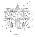
- FIG. 3 is an enlargement of the encircled region 3 shown in FIG. 2 .
- FIGS. 1-3 depict a valve assembly 10 constructed in accordance with the present invention.
- the valve assembly 10 comprises a heating device 12 which is operatively coupled to an exemplary valve 14 .
- the shape of the heating device 12 and positioning thereof upon the valve 14 are selected so as that the activation of the heating device 12 maintains the valve 14 at a temperature level above the saturation temperature of the related system pressure to effectively avoid the accumulation of condensate within the interior of the valve body and/or on other internal structural features of the valve 14 .
- the exemplary valve 14 integrated into the valve assembly 10 of the present invention is preferably a medium activated valve such as an isolation valve or a safety valve, and operates in accordance with what is commonly referred to as the “discharging principle.”
- a medium activated valve such as an isolation valve or a safety valve
- a common problem with valves which operate in accordance with the discharging principle and are used in steam control systems is the inevitable build up of condensate on the interior surfaces of the valve body of the valve, and/or other internal structure features thereof.
- the exemplary valve 14 comprises a valve housing or body 16 which, from the perspective shown in FIGS. 2 and 3 , includes an upper body section 18 and a lower body section 20 .
- the lower body section 20 of the valve body 16 defines a primary flow passage 22 through the valve body 16 .
- the inlet and outlet ends of the flow passage 22 and the main valve body chamber positioned therebetween are each defined by portions of the interior surface 24 of the lower body section 20 .
- the valve body 16 and in particular the upper and lower body sections 18 , 20 thereof, is typically fabricated from a metal material.
- the valve 14 includes a valve piston 26 , the majority of which resides within the main valve body chamber of the flow passage 22 .
- the valve piston 26 is selectively moveable between a closed position (shown in FIG. 2 ) wherein it is operative to block the flow of fluid (e.g., steam) between the inlet and outlet ends of the flow passage 22 .
- the valve piston 26 is moveable from its closed position to an open position whereat the inlet and outlet ends of the flow passage 22 are placed into fluid communication with each other via the main valve body chamber of the flow passage 22 .
- the valve piston 26 defines an upper valve piston chamber 28 and a lower valve piston chamber 30 .
- the valve piston 26 is typically fabricated from a metal material.
- valve 14 is further outfitted with a flow passage which communicates the upstream pressure flowing therein via the inlet end of the fluid passage 22 into the upper valve piston chamber 28 .
- upstream pressure is also introduced into the lower valve piston chamber 30 and tries to push the valve piston 26 from its closed position shown in FIG. 2 to its open position, such movement to the open position is opposed by that same pressure which, as indicated above, is also routed to the upper valve piston chamber 28 .
- the area of the valve piston 26 exposed to the upstream pressure in the upper valve piston chamber 28 is larger than that area of the valve piston 26 exposed to the upstream pressure in the lower valve piston chamber 30 , thus resulting in the valve piston 26 effectively being maintained in its closed position.
- the valve 14 includes at least one, and preferably a pair of pilot valves 32 which are cooperatively engaged to the valve body 16 .
- the pilot valves 32 are operative to selectively vent or exhaust the upper valve piston chamber 28 to either the downstream, outlet end of the flow passage 22 or to atmosphere.
- the opening of the pilot valves 32 as facilitates the venting or exhausting of the upper valve piston chamber 28 causes the pressure level in the upper valve piston chamber 28 to fall below that within the lower valve piston chamber 30 , thus facilitating the actuation of the valve piston 26 from its closed position shown in FIG. 2 to its open position.
- the fluid or steam pressure within the upper valve piston chamber 28 is exhausted to either the downstream, outlet end of the flow passage 22 or to atmosphere via one or more discharge paths (not shown) of the valve 14 which extend through the valve body 16 and are effectively routed through the pilot valves 32 as allows the discharge path(s) to be selectively opened and closed thereby.
- valve 14 will typically include other structural features in addition to the valve body 16 , valve piston 26 , pilot valves 32 , and the various flow and discharge paths or passages described above.
- additional internal structural features of the valve 14 may include, but are not limited to, biasing springs, seals, packing elements, etc.
- the structural features of the valve 14 as described above are intended to serve as only one example of a medium activated valve such as an isolation valve or safety valve which operates under the discharging principle.
- the valve 14 may be provided in any one of a plurality of configurations differing from those described above without necessarily departing from the spirit and scope of the present invention.
- valve assembly 10 constructed in accordance with the present invention is within a steam control system.
- all valves such as the valve 14
- the valves within the steam control system are typically insulated, the formation of the condensate still occurs as a result of insulation imperfections, which gives rise to an escape of heat and a condition wherein the steam itself heats up the valve, thus causing the temperatures of the valve body and internal structural features thereof to fall below the saturation temperature of the steam pressure within the system.
- another cause of condensate formation is attributable to transients pertaining to valve temperature.
- valve temperature which is usually connected to internal pressure, will not immediately follow the pressure change, but rather will remain at an established level for a longer period of time. This occurrence often results in the generation of condensate, since if a change in the valve temperature does not immediately follow a pressure change, the valve temperature will usually fall below the aforementioned saturation line.
- valve body 16 and at least the valve piston 26 fall below the saturation temperature within the steam control system will typically result in water or condensate forming on the interior surface 24 of the lower body section 20 of the valve body 16 and within at least the upper valve piston chamber 28 of the valve piston 26 .
- the heating device 12 integrated into the valve assembly 10 is particularly adapted to improve the operability of the valve 14 in a steam control environment by decreasing the opening time thereof.
- the decrease in the opening time is attributable to the heating device 12 effectively maintaining the temperature of the valve 14 , and in particular the valve body 16 and valve piston 26 thereof, constantly above the saturation temperature of the related steam system pressure, thus effectively avoiding the accumulation of water or condensate on the interior surface 24 of the lower body section 20 of the valve body 16 , within the upper valve piston chamber 28 of the valve piston 26 , and upon other internal structural features of the valve 14 .
- the particular heating device 12 integrated into the valve assembly 10 preferably has an annular, ring-like configuration. Additionally, when viewed from the perspective shown in FIGS. 2 and 3 , the heating device 12 is positioned upon the generally planar top surface of the upper body section 18 of the valve body 16 .
- FIG. 3 includes a number of arrows which depict the flow of heat from the activated heating device 12 to and through the valve body 16 , and to the internal structural features of the valve 14 , and notably the valve piston 26 thereof.
- the size and shape of the heating device 12 as shown in FIGS. 1-3 , and the particular position thereof on the valve body 16 are selected so as to optimize the ability of the heating device 12 to maintain both the valve body 16 and the internal structural features thereof (notably the valve piston 26 ) at a temperature higher than that of the saturation temperature of the steam within the valve 14 at a given pressure.
- any heating device cooperatively engaged thereto to prevent condensate formation therein in the aforementioned manner may have a size and/or shape differing from that of the aforementioned heating device 12 , and may further be positioned on such valve in any one of a multiplicity of differing locations, such location being selected to optimize the transmission of heat from the heating device to the valve body and internal structural features of such valve.
- the heating device 12 may be disposed on locations of the valve body 16 other than for the upper body section 18 thereof.
- the heating device 12 could potentially be directly engaged to the lower body section 20 without departing from the spirit and scope of the present invention.
- the ultimate objective in relation to the size, shape and location of the heating device 12 upon the valve 14 is that the heat generated by the heating device 12 will radiate symmetrically through the valve body 16 and into the internal structural features thereof (including the valve piston 26 ), as opposed to the heat generated by the heating device 12 being applied to only one part or portion of the valve 14 .
- the capacity of the heating device 12 is preferably selected so that it is operative to maintain the temperature of the valve 14 , and notably the valve body 16 and valve piston 26 thereof, in the range of about 5° to about 15° F. above the saturation temperature of the steam system pressure.
- the heating device 12 will be provided with a supply of electrical power (e.g., AC and/or DC) as shown in FIG. 1 . Further, it is contemplated that within the valve assembly 10 , the heating device 12 will be maintained in a powered, activated state at all times. In this regard, due to the valve body 16 , valve piston 26 and other components or structural features of the valve 14 typically being of a very large size and weight, a constant state of activation of the heating device 12 is usually necessary to effectively maintain the temperature of the valve 14 above that of the saturation temperature of the steam flowing therein.
- electrical power e.g., AC and/or DC
- valve 14 could optionally be provided with various temperature sensors in a prescribed arrangement as allows for constant monitoring of the temperature of the valve body 16 and/or other structural features thereof as would potentially allow for the heating device 12 to be periodically cycled off, and reactivated when the temperature of the valve 14 falls below a prescribed temperature level which is still above the saturation temperature of the steam system pressure.
Landscapes
- Engineering & Computer Science (AREA)
- General Engineering & Computer Science (AREA)
- Mechanical Engineering (AREA)
- Chemical & Material Sciences (AREA)
- Combustion & Propulsion (AREA)
- Fluid-Driven Valves (AREA)
- Details Of Valves (AREA)
- Temperature-Responsive Valves (AREA)
Priority Applications (5)
| Application Number | Priority Date | Filing Date | Title |
|---|---|---|---|
| US13/362,692 US8783283B2 (en) | 2012-01-31 | 2012-01-31 | Heating device for valve to prevent internal accumulation of condensate |
| CN201380007543.XA CN104204456B (zh) | 2012-01-31 | 2013-01-22 | 防止冷凝物的内部聚集的阀门加热装置 |
| PCT/US2013/022555 WO2013116042A1 (en) | 2012-01-31 | 2013-01-22 | Heating device for valve to prevent internal accumulation of condensate |
| EP13743127.6A EP2809900A4 (de) | 2012-01-31 | 2013-01-22 | Heizvorrichtung für ventil zur vermeidung von interner kondensatansammlung |
| KR1020147023366A KR20140125396A (ko) | 2012-01-31 | 2013-01-22 | 응축수의 내부 축적을 방지하기 위한 밸브용 가열 장치 |
Applications Claiming Priority (1)
| Application Number | Priority Date | Filing Date | Title |
|---|---|---|---|
| US13/362,692 US8783283B2 (en) | 2012-01-31 | 2012-01-31 | Heating device for valve to prevent internal accumulation of condensate |
Publications (2)
| Publication Number | Publication Date |
|---|---|
| US20130192677A1 US20130192677A1 (en) | 2013-08-01 |
| US8783283B2 true US8783283B2 (en) | 2014-07-22 |
Family
ID=48869223
Family Applications (1)
| Application Number | Title | Priority Date | Filing Date |
|---|---|---|---|
| US13/362,692 Active 2032-06-02 US8783283B2 (en) | 2012-01-31 | 2012-01-31 | Heating device for valve to prevent internal accumulation of condensate |
Country Status (5)
| Country | Link |
|---|---|
| US (1) | US8783283B2 (de) |
| EP (1) | EP2809900A4 (de) |
| KR (1) | KR20140125396A (de) |
| CN (1) | CN104204456B (de) |
| WO (1) | WO2013116042A1 (de) |
Cited By (1)
| Publication number | Priority date | Publication date | Assignee | Title |
|---|---|---|---|---|
| US20170030483A1 (en) * | 2014-12-02 | 2017-02-02 | Shih-Feng Liang | Temperature control valve |
Families Citing this family (2)
| Publication number | Priority date | Publication date | Assignee | Title |
|---|---|---|---|---|
| CN110023869A (zh) * | 2016-09-30 | 2019-07-16 | 贝利莫控股公司 | 具有加热设备的hvac致动器 |
| CN114156204B (zh) * | 2021-11-23 | 2025-09-16 | 北京北方华创微电子装备有限公司 | 源瓶组件及其温度控制方法、半导体工艺设备 |
Citations (8)
| Publication number | Priority date | Publication date | Assignee | Title |
|---|---|---|---|---|
| US1333558A (en) * | 1918-10-28 | 1920-03-09 | Minor Edward Lynnwood | Fuel-economizer for engines |
| US2704085A (en) * | 1952-09-04 | 1955-03-15 | Daco Machine & Tool Co | Valves for low temperature operation |
| US3617699A (en) * | 1969-03-10 | 1971-11-02 | Donald F Othmer | A system for electrically heating a fluid being transported in a pipe |
| US6227236B1 (en) * | 1999-11-22 | 2001-05-08 | Megatorr Corporation | Widely variable conductance valve |
| US6494229B2 (en) * | 2000-09-18 | 2002-12-17 | Smc Corporation | Pilot-type two-port vacuum valve |
| US20070151528A1 (en) | 2004-01-22 | 2007-07-05 | Cargine Engineering Ab | Method and a system for control of a device for compression |
| US20090077961A1 (en) | 2007-09-24 | 2009-03-26 | Baker David M | Heat Concentrator Piston and Chamber |
| US20100077986A1 (en) | 2008-09-28 | 2010-04-01 | Jack Yajie Chen | Steam Combustion Engine |
Family Cites Families (3)
| Publication number | Priority date | Publication date | Assignee | Title |
|---|---|---|---|---|
| US5915410A (en) * | 1996-02-01 | 1999-06-29 | Zajac; John | Pneumatically operated positive shutoff throttle valve |
| DE19719725A1 (de) * | 1997-05-09 | 1998-11-19 | Siemens Ag | Verfahren und Vorrichtung zum Erwärmen einer Ventilanordnung |
| US8967124B2 (en) * | 2006-03-21 | 2015-03-03 | Continental Automotive Systems, Inc. | Inductive heated injector using voltage transformer technology |
-
2012
- 2012-01-31 US US13/362,692 patent/US8783283B2/en active Active
-
2013
- 2013-01-22 EP EP13743127.6A patent/EP2809900A4/de not_active Withdrawn
- 2013-01-22 WO PCT/US2013/022555 patent/WO2013116042A1/en not_active Ceased
- 2013-01-22 CN CN201380007543.XA patent/CN104204456B/zh active Active
- 2013-01-22 KR KR1020147023366A patent/KR20140125396A/ko not_active Ceased
Patent Citations (8)
| Publication number | Priority date | Publication date | Assignee | Title |
|---|---|---|---|---|
| US1333558A (en) * | 1918-10-28 | 1920-03-09 | Minor Edward Lynnwood | Fuel-economizer for engines |
| US2704085A (en) * | 1952-09-04 | 1955-03-15 | Daco Machine & Tool Co | Valves for low temperature operation |
| US3617699A (en) * | 1969-03-10 | 1971-11-02 | Donald F Othmer | A system for electrically heating a fluid being transported in a pipe |
| US6227236B1 (en) * | 1999-11-22 | 2001-05-08 | Megatorr Corporation | Widely variable conductance valve |
| US6494229B2 (en) * | 2000-09-18 | 2002-12-17 | Smc Corporation | Pilot-type two-port vacuum valve |
| US20070151528A1 (en) | 2004-01-22 | 2007-07-05 | Cargine Engineering Ab | Method and a system for control of a device for compression |
| US20090077961A1 (en) | 2007-09-24 | 2009-03-26 | Baker David M | Heat Concentrator Piston and Chamber |
| US20100077986A1 (en) | 2008-09-28 | 2010-04-01 | Jack Yajie Chen | Steam Combustion Engine |
Non-Patent Citations (1)
| Title |
|---|
| International Search Report and Written Opinion for PCT/US13/22555. Issued Apr. 19, 2013. |
Cited By (2)
| Publication number | Priority date | Publication date | Assignee | Title |
|---|---|---|---|---|
| US20170030483A1 (en) * | 2014-12-02 | 2017-02-02 | Shih-Feng Liang | Temperature control valve |
| US9951884B2 (en) * | 2014-12-02 | 2018-04-24 | Huo Jhih Co., Ltd. | Temperature control valve |
Also Published As
| Publication number | Publication date |
|---|---|
| US20130192677A1 (en) | 2013-08-01 |
| CN104204456B (zh) | 2019-10-01 |
| CN104204456A (zh) | 2014-12-10 |
| EP2809900A1 (de) | 2014-12-10 |
| KR20140125396A (ko) | 2014-10-28 |
| EP2809900A4 (de) | 2015-09-02 |
| WO2013116042A1 (en) | 2013-08-08 |
Similar Documents
| Publication | Publication Date | Title |
|---|---|---|
| JP6290923B2 (ja) | ポンプのスタートアップが簡便な背圧調節装置 | |
| US10962162B2 (en) | Fluid-regulator with field convertible slam-shut device | |
| EP2674594B1 (de) | Temperaturabhängige Baugruppe für ein Gasturbinensystem und Verfahren zur Steuerung eines Weges einer kühlenden Luftströmung | |
| US8783283B2 (en) | Heating device for valve to prevent internal accumulation of condensate | |
| CN102498323B (zh) | 减压阀 | |
| KR20160053911A (ko) | 진공 시스템 내에서 작동하는 유체 작동 기계용 시동 밸브 | |
| CN103140367A (zh) | 安全阀及燃料蒸汽阀组件 | |
| US9733028B2 (en) | Bypass valve with a hollow shaft and a memory metal alloy spring | |
| KR101408008B1 (ko) | 에어 밸브 | |
| JP2016534289A (ja) | ターボ機械のための弁 | |
| KR101989186B1 (ko) | 벨브를 구비한 밸브 및 펌프 조립체 | |
| CN117398901B (zh) | 高低温湿热试验箱增湿用调控保护单元 | |
| KR101610412B1 (ko) | 연료전지차량의 이온필터장치 | |
| BR102013029483B1 (pt) | Cabeça de cilindro para um compressor de pistão | |
| KR101629562B1 (ko) | 온도조절밸브 | |
| JP6908784B2 (ja) | 圧縮機を制御するガバナー装置 | |
| KR200453655Y1 (ko) | 진공 방지 기능이 구비된 스팀 안전 압력변 | |
| CN204805697U (zh) | 弯曲销触发型先导式泄压阀 | |
| EP2454530B1 (de) | Vorrichtung zur belüftung eines systems | |
| EP2588812B1 (de) | Druckentlastungsanordnung für eine waschkammer | |
| KR20230045750A (ko) | 열배출기를 포함하는 팬필터유닛 | |
| JP2010216538A (ja) | 熱応動式スチームトラップ | |
| KR20160058439A (ko) | 배관 동파 방지장치 |
Legal Events
| Date | Code | Title | Description |
|---|---|---|---|
| AS | Assignment |
Owner name: CONTROL COMPONENTS, INC., CALIFORNIA Free format text: ASSIGNMENT OF ASSIGNORS INTEREST;ASSIGNORS:KRIZ, DAVOR;ZIEGER, TOBIAS;BAUMANN, PETER;AND OTHERS;REEL/FRAME:027744/0812 Effective date: 20120203 |
|
| STCF | Information on status: patent grant |
Free format text: PATENTED CASE |
|
| MAFP | Maintenance fee payment |
Free format text: PAYMENT OF MAINTENANCE FEE, 4TH YEAR, LARGE ENTITY (ORIGINAL EVENT CODE: M1551) Year of fee payment: 4 |
|
| MAFP | Maintenance fee payment |
Free format text: PAYMENT OF MAINTENANCE FEE, 8TH YEAR, LARGE ENTITY (ORIGINAL EVENT CODE: M1552); ENTITY STATUS OF PATENT OWNER: LARGE ENTITY Year of fee payment: 8 |
|
| AS | Assignment |
Owner name: IMI CRITICAL ENGINEERING LLC, DELAWARE Free format text: CHANGE OF NAME;ASSIGNOR:CONTROL COMPONENTS, INC.;REEL/FRAME:073433/0596 Effective date: 20221231 |
|
| MAFP | Maintenance fee payment |
Free format text: PAYMENT OF MAINTENANCE FEE, 12TH YEAR, LARGE ENTITY (ORIGINAL EVENT CODE: M1553); ENTITY STATUS OF PATENT OWNER: LARGE ENTITY Year of fee payment: 12 |