US8772708B2 - Time-of-flight mass spectrometer - Google Patents
Time-of-flight mass spectrometer Download PDFInfo
- Publication number
- US8772708B2 US8772708B2 US13/996,372 US201113996372A US8772708B2 US 8772708 B2 US8772708 B2 US 8772708B2 US 201113996372 A US201113996372 A US 201113996372A US 8772708 B2 US8772708 B2 US 8772708B2
- Authority
- US
- United States
- Prior art keywords
- ion
- potential
- reflector
- time
- ions
- Prior art date
- Legal status (The legal status is an assumption and is not a legal conclusion. Google has not performed a legal analysis and makes no representation as to the accuracy of the status listed.)
- Active
Links
Images


Classifications
-
- H—ELECTRICITY
- H01—ELECTRIC ELEMENTS
- H01J—ELECTRIC DISCHARGE TUBES OR DISCHARGE LAMPS
- H01J49/00—Particle spectrometers or separator tubes
- H01J49/26—Mass spectrometers or separator tubes
- H01J49/34—Dynamic spectrometers
- H01J49/40—Time-of-flight spectrometers
- H01J49/405—Time-of-flight spectrometers characterised by the reflectron, e.g. curved field, electrode shapes
-
- G—PHYSICS
- G01—MEASURING; TESTING
- G01N—INVESTIGATING OR ANALYSING MATERIALS BY DETERMINING THEIR CHEMICAL OR PHYSICAL PROPERTIES
- G01N27/00—Investigating or analysing materials by the use of electric, electrochemical, or magnetic means
- G01N27/62—Investigating or analysing materials by the use of electric, electrochemical, or magnetic means by investigating the ionisation of gases, e.g. aerosols; by investigating electric discharges, e.g. emission of cathode
-
- H—ELECTRICITY
- H01—ELECTRIC ELEMENTS
- H01J—ELECTRIC DISCHARGE TUBES OR DISCHARGE LAMPS
- H01J49/00—Particle spectrometers or separator tubes
- H01J49/26—Mass spectrometers or separator tubes
- H01J49/34—Dynamic spectrometers
- H01J49/40—Time-of-flight spectrometers
- H01J49/403—Time-of-flight spectrometers characterised by the acceleration optics and/or the extraction fields
Definitions
- the present invention relates to a time-of-flight mass spectrometer, and more specifically to a time-of-flight mass spectrometer using an ion reflector.
- TOFMS time-of-flight mass spectrometer
- the time of flight required for ions ejected from an ion source to reach an ion detector is measured, and the mass (or mass-to-charge ratio m/z, to be exact) of each ion is calculated from the time of flight of that ion.
- One major cause of deterioration in the mass-resolving power is the initial energy distribution of the ions.
- An initial energy distribution of the ions ejected from the ions source causes a time-of-flight distribution of the ions of the same mass and deteriorates the mass-resolving power.
- ion reflectors have been widely used.
- a TOFMS using an ion reflector is hereinafter called the “reflectron” according to the common practice.
- An ion reflector has an electric potential increasing in the traveling direction of the ions, and has the function of repelling ions coming through a field-free drift space.
- An ion having a higher initial energy (initial speed) penetrates deeper into the ion reflector and hence spends a longer period of time flying in the ion reflector when reflected.
- an ion having a larger amount of initial energy flies at a higher speed and hence spends a shorter period of time flying through the drift space of a fixed length.
- one type is a multi-stage system in which a plurality of regions with a uniform (or nearly uniform) electric field are connected in series
- the other type is a non-uniform electric field system in which the potential continuously changes with the intensity of the electric field defined as a function of the distance.
- the multi-stage system is hereinafter described.
- the structurally simplest version of the multi-stage system is the single-stage reflectron.
- a potential of the single-stage reflectron is schematically shown in FIG. 23 (see Non-Patent Document 1).
- the ion reflector has a uniform electric field (i.e. the potential U is proportional to the distance X).
- a grid electrode G through which ions can pass is provided at the boundary between the field-free drift region and the ion reflector.
- L is the length of the field-free drift space
- a is the penetration depth of the ions into the ion reflector.
- the first-order focusing position the position corresponding to the depth a in the single-stage reflectron is called the “first-order focusing position.”
- FIG. 24 is a schematic potential diagram of a dual-stage reflectron.
- the dual-stage reflectron was developed for the first time by Mamyrin et al. (see Non-Patent Document 2).
- the ion reflector consists of two uniform electric fields, with a grid electrode G provided as a partition at the boundary between the field-free drift region and the first uniform electric field (first stage) as well as at the boundary between the first uniform electric field and the second uniform electric field (second stage). If the first stage is adequately short, and if approximately two thirds of the initial energy is lost in the first stage, the time-of-flight distribution is compensated for up to the second derivative of the energy. That is to say, the second-order energy focusing (which hereinafter is simply called “the second-order focusing”) is achieved and a high mass-resolving power is obtained.
- the second-order energy focusing which hereinafter is simply called “the second-order focusing”
- Equations (2) suggest that, if the lengths b and c are given, the values of a and p which satisfy the second-order focusing condition can be uniquely determined.
- the time-of-flight distribution is compensated for up to the second derivative of the ion energy, a high mass-resolving power can be achieved for ions having a broader energy distribution than in the case of the single-stage reflectron.
- the position corresponding to the depth a in the dual-stage reflectron is called the “second-order focusing position.”
- a multi-stage reflectron which can be conceived as an extension of the dual-stage reflectron, it can be generally expected that increasing the number of uniform electric fields (or nearly uniform electric fields) in the multi-stage reflectron improves the performance, with the time-of-flight distribution being compensated for up to higher-order derivatives of the ion energy (the cancellation of up to the N-th derivative is hereinafter called the “N-th order focusing”), thus making it possible to achieve a high mass-resolving power for ions having a broader energy distribution.
- Non-Patent Document 5 includes a report of the results obtained by correcting the design parameters up to higher-order derivatives without departing from the practically acceptable ranges of the parameters while increasing the number of stages in the ion reflector up to four.
- increasing the number of stages does not lead to a significant increase in the energy range in which a high level of mass-resolving power is obtained.
- increasing the number of grid electrodes placed on the flight path of the ions causes a greater amount of loss of the ions and deteriorates the sensitivity. Such a system can be said to be practically unusable.
- the non-uniform electric field system has been developed as an attempt to reduce the time-of-flight distribution of the ions having an even broader energy distribution.
- An ideal pinnacle of this system is a reflectron using a simple harmonic motion.
- Patent Document 1 A technique for solving this drawback is disclosed in Patent Document 1 and Non-Patent Document 4, in which the sum of a potential proportional to the distance X and a potential proportional to the square of the distance X is used as the potential inside the reflector, with the aim of reducing the time-of-flight distribution even in the case where a field-free drift region is connected to an ion reflector having a gradient electric field.
- This method ensures a certain level of energy-focusing performance over a comparatively broad range of energy.
- it also makes the negative effect of breaking the exact isochronism, thus limiting the improvement of the mass-resolving power.
- Patent Document 2 a configuration of a TOF-TOF system for performing an MS 2 analysis is described in Patent Document 2.
- a non-uniform electric-field potential is created inside a second ion reflector for the purpose of the energy focusing of the fragment ions produced in a collision cell.
- Patent Document 4 and Non-Patent Document 7 the entire ion reflector is divided into a decelerating region as the first section and a (non-uniform) correcting potential region as the second section.
- Patent Document 3 A system which has significantly contributed to the practical realization of a reflectron having both high mass-resolving power and high energy-focusing performance (i.e. high sensitivity) is the system described in Patent Document 3.
- This system which can be regarded as a compromise between the multi-stage uniform electric-field system and the non-uniform electric-field system, is a variation of the dual-stage reflectron in which the entire first stage and a portion of the second stage are designed to be a uniform electric-field region using an approximately constant electric field, while the remaining portion extending to the end is designed to be a correcting potential region with a non-uniform electric field adopted therein, whereby the electric-field strength on the central axis is made to substantially increase.
- the electric-field strength in the first stage is set at a low level so as to improve the ion-beam focusing performance, with a corresponding sacrifice of the mass-resolving power.
- the amount of correction of the electric-field strength in the second stage is 10% of the uniform electric-field strength or even smaller.
- an ideal reflectron is herein defined as “a reflectron capable of the energy focusing up to infinitely high-order terms for a time-of-flight distribution by using a potential distribution created by a non-uniform electric field, at any energy level equal to or higher than a specific level E 0 .”
- ⁇ 3 Suppression of Off-Axis Aberration> An off-axis aberration, i.e. the temporal aberration for an ion on a path dislocated from the central axis, should be suppressed.
- T ( E ) T ( E 0 )+( dT/dE )( E ⁇ E 0 )+(1 ⁇ 2)( d 2 T/dE 2 ) ⁇ ( E ⁇ E 0 ) 2 +(1 ⁇ 6)( d 3 T/dE 3 )( E ⁇ E 0 ) 3 + . . . (5), where E is the initial energy of the ion, and T(E) is the time of flight of the ion.
- a Wiley-McLaren solution uses the first-order focusing which cancels the terms of equation (5) up to the first-order differential coefficient by a single-stage reflectron, using a potential created by a uniform electric field.
- a Mamyrin solution uses the second-order focusing which cancels the terms of equation (5) up to the second-order differential coefficient by a dual-stage reflectron.
- the conditions ⁇ 2: Suppression of Beam Divergence> and ⁇ 3: Suppression of Off-Axis Aberration> are also essential for the practical realization of an ideal reflectron. Both the beam dispersion and the temporal aberration occur due to the fact that divE ⁇ 0 for a non-uniform electric field in vacuum. Firstly, if the discrepancy from the uniform electric field is large or the curvature of the potential distribution is large, the ion reflector acts as a concave lens, which causes a divergence of the ion trajectory and eventually lowers the signal intensity.
- the condition ⁇ 4: Feasibility of Potential> is also important from practical points of view, because, even if a correcting potential to be created inside the reflector to achieve complete isochronism has been theoretically determined, that potential cannot always be actually created as a three-dimensional potential distribution.
- this determination task is mainly substituted for by the task of initially determining a 1D-IDL, which can be obtained with almost zero numerical discrepancy from ideal values, and then performing numerical calculations on a large scale to obtain a three-dimensional approximate solution 3D-SIM corresponding to that 1D-IDL for a specified set of electrodes.
- the correcting potential is analytically determined on the premise that the electric field which serves as a base before the correction in the vicinity of the beginning portion of the correcting potential is a uniform electric field.
- the electric field at the grid electrode placed at the boundary of the electric field is actually disordered due to the seeping of the electric field or other factors, and this disorder fatally deteriorates the isochronism.
- the problem is even more serious because the degree of non-uniformity of the electric field is greater.
- the correcting potential must be obtained by using a system as close to a real form as possible.
- Patent Document 3 does not exactly satisfy the condition ⁇ 1: Complete Isochronism>.
- ⁇ 1 Complete Isochronism>.
- the system can be said to be closer to an ideal reflectron.
- a problem exists in that it requires repeating a trial and error process in a computer simulation in order to find a sufficient potential distribution for achieving a required mass-resolving power. It is impractical to use such a trial and error process in order to reach an ideal extremity, i.e. a solution that exactly satisfies the conditions for isochronism.
- the energy range in which a practical isochronism is achieved is also limited.
- Step 1 An ideal potential distribution in the correcting potential region is expressed as a general solution including design parameters (distance and voltage).
- Step 2 The general solution obtained in Step 1 is expanded into a half-integer power series of (U ⁇ E 0 ).
- Step 3 The design parameters are adjusted so that the expansion coefficients obtained in Step 2 will be individually zeroed.
- the N-th order focusing position can be more specifically defined as follows. Provided that the total time of flight is expressed as a function of energy E, the N-th order focusing position is the position on the central axis at which the potential value is equal to the energy E at which the first through N-th order derivative values are equal to zero.
- the N-th order focusing position does not always exist in an arbitrary design; the fact is that there are considerable ranges of design parameters in which no N-th order focusing position can be found. This means that the situation with no N-th order focusing position existing from the start may more frequently occur depending on the setting of the design parameters.
- Non-Patent Document 8 (which is hereinafter called the “document of Doroshenko”) is a study that succeeded the technique described in the documents of Cotter et al. Similar to Cotter et al., the study is focused on the one-dimensional model. In the documents of Cotter et al., the entire flight path of the ions including the ion source (or ion-accelerating region) is divided into a forward path (upstream region), a return path (downstream region) and a reflector region with a correcting potential, and a generalized integral equation for determining an ideal potential distribution within the reflector region for achieving isochronism for an arbitrary potential distribution on the forward and return paths is presented.
- the present invention has been developed to solve the previously described problems, and its objective is to provide a reflectron as an ideal pinnacle. Specifically, it is a reflectron that satisfies the following conditions: a discrepancy from the uniform electric field which causes a serious divergence of the ions should not occur; the influence of the off-axis temporal aberration should be suppressed; and a practical isochronism should be achieved for an ion traveling on the central axis. More specifically, the objective of the present invention is to provide a three-dimensional, highly feasible, ideal reflectron which completely satisfies the aforementioned conditions ⁇ 1: Complete Isochronism> through ⁇ 5: Tolerance for Non-Uniform Electric Field before Correction>
- One problem for the present invention is to obtain a practical potential distribution which achieves isochronism over a wider energy range than the conventional techniques and which has a small curvature of the potential distribution, even in the case where a field-free drift space is present. The reason is because it is most likely that, once such a potential distribution is determined, the work of designing a system and adjusting experimental parameters will be easy.
- Another problem for the present invention is to provide a reflectron with which isochronism is achieved for the entire mass spectrometric system including the ion source, which is an indispensible component of the mass spectrometer.
- the technique adopted in the present invention it is possible not only to find a general solution of an ideal potential distribution presented in the documents of Cotter et al, but also to determine a particular solution which gives a potential distribution having a sufficiently small curvature for practical application (i.e. which satisfies the conditions ⁇ 2: Suppression of Beam Divergence> through ⁇ 5: Tolerance for Non-Uniform Electric Field before Correction>) and which is specific.
- Step 1 Setting of Base Potential
- a model which approximately achieves isochronism is considered, referring to a multi-stage reflectron such as the Wiley-McLaren solution or the Mamyrin solution.
- the potential distribution X A (U) of the thus optimized model is the target to be corrected and improved, which is hereinafter called the “base potential”.
- Step 2 Superposition of Correcting Potential
- This resultant potential X R (U) is the very potential which should be actually realized on the central axis. This potential is hereinafter called the “real potential”.
- the position at which the superposition of the correcting potential begins is the first-order focusing position in the Wiley-McLaren solution, the second-order focusing position in the Mamyrin solution, and the like.
- the correcting potential X C (U) is superposed on the region deeper than this point inside the reflector.
- Step 1 an optimized correcting potential X C (U) is determined from a generally known fact (that it is possible to make the first or second derivative equal to zero by using only uniform electric fields, and to uniquely determine the first or second-order focusing position). As will be described later, this step guarantees that a practically usable particular solution with a small curvature of the potential distribution can be obtained under given constraints.
- This technique is based on the completely new technical idea that lower-order terms (such as the first and second terms) in equation (5) are initially cancelled beforehand by the Wiley-McLaren or Mamyrin solution, after which the remaining higher-order terms are cancelled by the correcting potential.
- the condition that a single-stage reflector or a multi-stage reflector with two or more stages should be composed of only uniform electric fields is removed, so that a reflector including a non-uniform electric field may also be included.
- the base potential X A (U) will not always be a potential created by uniform electric fields. Even in that case, the starting point of the superposition of the correcting potential is set at the N-th order focusing position newly obtained by a numerical calculation or similar method.
- the time-of-flight mass spectrometer uses an ideal potential distribution obtained by the previously described new technique. Specifically, it is a time-of-flight mass spectrometer including an ion ejector for accelerating target ions by imparting a certain amount of energy to the ions, an ion reflector for reflecting ions ejected from the ion ejector and turning the ions around by an effect of an electric field, an ion detector for detecting the ions reflected by and exiting from the ion reflector, and a reflector driver for driving the ion reflector so as to create a reflecting electric field inside the ion reflector, wherein:
- the reflector driver applies a voltage to the ion reflector so as to create, inside an inner hollow area of the ion reflector and along the central axis of the ion reflector, a predetermined potential distribution U A (X) in which the potential monotonously changes over the entire ion reflector and therefore an inverse function X A (U) can be uniquely obtained, thus creating an N-th order focusing position at a position with coordinate X 0 and potential E 0 inside the ion reflector; and
- the reflector driver also applies a voltage to the ion reflector within a space having the N-th order focusing position with coordinate X 0 as a starting point and extending into a deeper region, so as to superpose, on the predetermined potential X A (U), a predetermined correcting potential X C (U) which can be approximated by a formula proportional to ⁇ U(X) ⁇ E 0 ⁇ N+3/2 in the vicinity of the coordinate X 0 and which is expressed as a smooth function continuing from the coordinate X 0 into the deeper region.
- a forward ion drift region for making the ions ejected from the ion ejector fly forward is provided between the ion ejector and the ion reflector, the ion reflector subsequently reflects the ions passing through the forward ion drift region and turns the ions around by the effect of the electric field, and a backward ion drift region for making the ions reflected by and exiting from the ion reflector fly in a direction opposite to the forward ion drift region is provided between the ion reflector and the ion detector.
- These ion drift regions may be field-free drift regions for making the ions fly freely.
- the forward ion drift region and the backward ion drift region are not indispensible; it is possible to adopt the configuration in which the ion ejector and the ion reflector, as well as the ion reflector and the ion detector, are connected to each other with no drift region or similar space provided in between.
- the electric field which is to be the predetermined potential distribution X A (U) may be a uniform electric field at least in the vicinity of the coordinate X 0 .
- the electric field may be a uniform electric field not only in the vicinity of the coordinate X 0 but also over the entire ion reflector.
- a grid electrode may be provided inside the inner hollow area of the ion reflector, the grid electrode dividing the ion reflector into a plurality of stages.
- the ion reflector operates as a single-stage ion reflector or a multi-stage ion reflector with two or more stages. It is also possible to adopt a grid-less structure with no grid electrode provided inside the inner hollow area of the ion reflector.
- the predetermined potential distribution X A (U) may be created by a non-uniform electric field.
- N In the time-of-flight mass spectrometer according to the present invention, there is theoretically no upper limit of the value of N. However, in practice, increasing the value of N makes it more difficult to calculate the N-th order focusing position. To avoid this situation, and in respect of the cancellation of higher-order terms by the correcting potential, N may be as small as one or two, which is sufficient for practical purposes.
- the ion ejector can be constructed in various forms, such as an orthogonal acceleration ion source or MALDI (matrix-assisted laser desorption/ionization) ion source.
- MALDI matrix-assisted laser desorption/ionization
- an aperture or slit for limiting the passing area of the ions may be provided between the ion ejector and the reflector in order to suppress an influence from the off-axis aberration.
- the forward ion drift region and the backward ion drift region are provided in the time-of-flight mass spectrometer according to the present invention, such ion drift regions, in most cases, have no electric fields. However, it is possible to provide an accelerating or decelerating region in a portion of the ion drift regions.
- a focusing lens for suppressing the influence of the off-axis aberration may be set in a portion of the forward ion drift region, or the ion ejector may be provided with the effect of a focusing lens.
- the ion reflector can also be constructed in various forms.
- the ion reflector may include a plurality of thin electrodes arranged along an ion beam axis.
- the reflector driver can be constructed as a voltage source for applying a predetermined direct-current voltage to each of the plurality of thin electrodes individually.
- Another example is a system in which the plurality of thin electrodes are individually connected to each resistor included in a resistor network, with a predetermined voltage applied between the two ends of the resistor network so that an appropriate fraction of the voltage is applied to one of the thin electrodes.
- the ion reflector may include a resistance element having an electric resistance adjusted along the ion beam axis. If such a resistance element is used, the potential can be continuously changed along the ion beam axis, so that a more ideal potential can be formed than in the case of using a plurality of thin electrodes.
- the ion reflector may be created using a printed board or a substrate produced by a high-precision microfabrication technique. If a plurality of electrodes are formed on a printed board or microfabricated substrate by etching or other processes, a higher level of precision in the position of the electrodes can be achieved at a lower cost than in the case of using a plurality of thin electrodes.
- the processing accuracy can be as high as several tens of micrometers for printed boards, and a few micrometers to submicron levels for microfabricated substrates.
- the time-of-flight mass spectrometer according to the present invention is not limited to a TOFMS having a single ion reflector; it may be designed as a multi-reflection time-of-flight mass spectrometer including a plurality of ion reflectors arranged opposite to each other so that ions are reflected a plurality of times between the plurality of ion reflectors, with at least one of the plurality of ion reflectors being the aforementioned ion reflector in which a predetermined correcting potential X C (U) is superposed on the predetermined potential X A (U).
- This design can provide an extremely long flight distance, and therefore, is particularly effective for improving the mass-resolving power.
- time-of-flight mass spectrometer With the time-of-flight mass spectrometer according to the present invention, a high level of energy-focusing performance can be achieved for ions with a broader energy distribution than before by using a truly ideal reflectron which could not be conventionally realized. Therefore, for example, even if the ions at the point of ejection are broadly distributed over a large space within an ion source (ion ejector) and there is a significant variation in the amount of energy imparted to them, a high level of mass-resolving power is achieved. The divergence of the ions inside the ion reflector is also prevented, as a result of which the detection sensitivity of the ions is also improved.
- a reflectron having both high mass-resolving power and high sensitivity can be provided, overcoming the restriction for the conventional reflector-type TOFMSs that there is a trade-off between the mass-resolving power and the sensitivity. Since an ideal extremity of the potential distribution is uniquely determined, the difficult task of adjusting the system parameters by a complicated process is no longer necessary, and therefore, the cost of the system design can be lowered. Furthermore, the high energy-focusing performance means that the position of the TOF peaks will not be affected by a change in the initial energy of the ions, which significantly contributes to an enhancement of the mass accuracy.
- FIG. 1 is a schematic profile of a base potential to be used as a basis for determining an ideal form of the real potential for a single-stage reflectron.
- FIG. 3A is a graph showing a calculation result (1D-IDL) of the real potential X R (U) and the base potential X A (U) in the system shown in FIG. 1
- FIG. 3B is a graph showing a calculation result (1D-IDL) of the correcting potential X C (U).
- FIG. 4 is a graph showing a calculation result (1D-IDL) of the relationship between the relative value ⁇ T/T of the discrepancy of the time of flight and the initial energy in the system shown in FIG. 1 .
- FIG. 5A is a graph showing a calculation result of the relationship between the displacement Rdet from the central axis of the ions which arrived at a detector and the relative energy distribution ⁇ U/U
- FIG. 5B is a graph showing a calculation result (3D-SIM) of the relationship between the relative energy distribution ⁇ U/U and the relative temporal distribution ⁇ T/T, in the case where ions traveled on a path dislocated from the central axis of a single-stage reflectron.
- FIG. 6 is a graph showing an error between an ideal form of the real potential (1D-IDL) for a single-stage reflectron and a three-dimensional approximate potential distribution (3D-SIM) corresponding to that ideal form.
- FIG. 7 is a schematic profile of a base potential to be used as a basis for determining an ideal form of the real potential for a dual-stage reflectron.
- FIG. 9A is a graph showing a calculation result (1D-IDL) of the real potential X R (U) and the base potential X A (U) in the system shown in FIG. 7
- FIG. 9B is a graph showing a calculation result (1D-IDL) of the correcting potential X C (U).
- FIG. 10A is a conceptual diagram showing a relationship between the base potential and the real potential in the system shown in FIG. 7
- FIG. 10B is a conceptual diagram showing the contributions of the base potential and the real potential to the entire time of flight.
- FIG. 11 is a graph showing a calculation result (1D-IDL) of the relationship between the relative value ⁇ T/T of the discrepancy of the time of flight and the initial energy in the system shown in FIG. 7 .
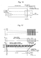
- FIG. 12 is a graph showing a calculation result (3D-SIM) of the relationship between the relative energy distribution ⁇ U/U and the relative temporal distribution ⁇ T/T in the case where ions travel on the central axis of an ion reflector.
- FIGS. 13A and 13B are graphs showing calculation results (3D-SIM) of the displacement Rdet from the central axis of the ions which arrived at a detector and the relative temporal distribution ⁇ T/T, with respect to the relative energy distribution ⁇ U/U, in the case where ions travel on a path dislocated from the central axis of a dual-stage reflectron.
- FIG. 14 is a graph showing an error between an ideal form of the real potential (1D-IDL) for a dual-stage reflectron and a three-dimensional approximate potential distribution (3D-SIM) corresponding to that ideal form.
- FIG. 15A is a graph showing a relationship between the initial energy E and the relative temporal distribution dT/T in a dual-stage reflectron composed of only uniform electric fields
- FIG. 15B is a graph showing the base potential inside the reflector.
- FIG. 16 is a modeled configuration diagram for analyzing the conditions for complete isochronism for a non-periodic motion.
- FIG. 17 is a model diagram showing the electrode shape and the potential shape used in a simulation performed for an orthogonal acceleration reflectron having a single accelerating region consisting of a uniform electric field.
- FIG. 18 is a result of a simulation (3D-SIM) performed on the assumption that the grid electrode in the system shown in FIG. 17 is an ideal grid electrode.
- FIG. 20 is a graph showing an ideal form of the real potential (1D-IDL) in a system using a parallel wire-grid electrode as the boundary of the electric fields, and the discrepancy of a corresponding three-dimensional approximate potential distribution (3D-SIM) from the ideal values.
- FIG. 21 is a graph showing a result of a simulation (3D-SIM) of the system shown in FIG. 17 using a practical grid electrode and taking into account the seeping of the electric field at the grid electrode.
- FIG. 22 is a schematic configuration diagram of a TOFMS according to one embodiment of the present invention.
- FIG. 23 is a schematic potential chart of a commonly used single-stage reflectron.
- FIG. 24 is a schematic potential chart of a commonly used dual-stage reflectron.
- FIGS. 25A and 25B are graphs showing a method for distinguishing between the base potential and the correcting potential.
- the ion source (ion ejector) is not included as a component of the system; ions which have begun their flight from a certain point inside the field-free drift region with different amounts of initial energy are reflected by the reflector and arrive at the detector.
- the guard-ring electrodes used in the simulation (with an electrode thickness of 0.2 mm) have a circular opening (with an inner diameter of 40 mm) and are arranged at intervals of 5 mm, with no upper limit of the number of the electrodes.
- the electric field inside the ion reflector is a uniform electric field.
- a method for designing an ion reflector of the TOFMS according to the present invention is hereinafter described along two specific examples, i.e. a single-stage reflectron and a dial-stage reflectron.
- a method for calculating the base potential X A (U) and the correcting potential X C (U) for a model of a single-stage reflectron having a single uniform electric field is hereinafter described in detail.
- U is the potential value
- X* is the coordinate along the central axis
- “*” is an arbitrary subscript for distinction.
- X*(U) normally means the inverse function of the potential distribution.
- this inverse function X*(U) is also simply called the potential in the following description.
- T S (E) 4 ⁇ [L / ⁇ square root over (2 E/m ) ⁇ ]+( a/U a ) ⁇ square root over (2 mE ) ⁇ (7-1).
- T free (E) is the period of time required for the ion to pass through the field-free drift region
- T ref-a (E) is the period of time required for the ion to fly in the uniform electric field inside the ion reflector.
- a correcting potential is superposed on the base potential X A (U) created by the uniform electric field expressed by equation (6) in order to find a solution for achieving complete isochronism.
- the best case scenario is that isochronism is achieved by simply adding, within the range of
- X R L+a
- Non-Patent Document 6 discloses a method by which the aforementioned real potential X R (U) (i.e. the inverse function of a potential distribution U(X) which yields the given time of flight) can be calculated back from an arbitrary time of flight T(E) for one turn.
- the following equation (8) is an equation originally presented as equation (12.2) in Non-Patent Document 6:
- equation (8) can be rewritten as the following equation (9-1):
- equation (9-3) which has been derived by the present inventors, shows that the correcting potential X C (U) can be maintained at small values by reducing the value of T S (1) ⁇ T S (E) included in the integral.
- Non-Patent Document 5 The presence of such a solution is guaranteed by Non-Patent Document 5.
- a calculation result (1D-IDL) of the real potential X R (U) is shown in FIG. 3A .
- the potential for U ⁇ 1 is the same as the base potential X A (U) created by the uniform electric field, while the potential for U>1 is composed of the base potential X A (U) of the uniform electric field of the same strength with an extremely small correcting potential X C (U) added thereto.
- FIG. 3B is a double logarithmic graph (1D-IDL) of the correcting potential X C (U) plotted against U ⁇ 1, which shows that the correcting potential in the present case lies on an approximately straight line, maintaining the relationship of X C (U) ⁇ (U ⁇ 1) 2.5 within a range where U ⁇ 1 is small.
- the time of flight TOF(E) can be calculated by the following equation (10):
- FIG. 4 shows the calculation results (1D-IDL) for the cases with or without the correcting potential.
- the correcting potential i.e. in the case of the conventional technique of Wiley McLaren solution
- the range within which the discrepancy of the time of flight is small is considerably narrow; the energy range where ⁇ T/T ⁇ 10 ⁇ 4 is achieved is no greater than ⁇ 3%.
- RS mass-resolving power
- Such a disappearance of symmetry cannot occur in a multi-stage reflectron; to realize such a state, it is necessary to add a correcting potential that cannot be extended into the lower-energy region (U ⁇ 1), as in the case of X C (U) ⁇ (U ⁇ 1) 2.5 .
- a half-integer power is indispensible for creating such an asymmetrical state.
- a verification simulation (3D-SIM) has been performed to determine whether a practical isochronism can be achieved even by an approximate potential distribution created by a limited number of guard-ring electrodes.
- 3D-SIM a verification simulation for a single-stage reflectron
- the system parameters were adjusted so that the uniform electric field serving as the base at the starting point of the correcting potential would have the same strength in both simulations.
- the total length of the reflectron was 670 mm.
- the guard-ring electrodes had 134 plate electrodes arranged at intervals of 5 mm, with each plate electrode measuring 40 mm in inner diameter and 0.2 mm in thickness.
- the potential is corrected within the range of equal to or higher than 5600 V so as to enable the energy focusing of the ions with an energy distribution of 7 keV ⁇ 20%.
- An appropriate voltage was applied to each of the guard-ring electrodes so as to create an ideal form of the real potential on the central axis of the reflectron.
- FIG. 5A shows a calculation result (3D-SIM) of the relationship between the discrepancy Rdet from the central axis of the ions which arrived at a detector and the relative energy distribution ⁇ U/U
- FIG. 5B shows a calculation result (3D-SIM) of the relationship between the relative energy distribution ⁇ U/U and the relative temporal distribution ⁇ T/T, in the case where the ions traveled on a path parallel to and dislocated from the central axis of the reflectron (with the amount of displacement denoted by R).
- 5A demonstrates that no divergence occurs within the range of ⁇ U/U ⁇ 0.2, since ions are reflected by the uniform electric field in the region before the first-order focusing position and cannot reach the correcting potential region.
- a divergence occurs within the range of ⁇ 0.2 ⁇ U/U ⁇ 0.2 where ions are reflected in the correcting potential region.
- the equipotential surfaces are approximately parallel to each other and the divergence is suppressed to the minimum. The extent of divergence increases with the increase in the displacement R.
- FIG. 6 shows an error between an ideal form of the real potential (1D-IDL) for a single-stage reflectron and a three-dimensional approximate potential distribution (3D-SIM) corresponding to that ideal form.
- a considerably large magnitude of relative temporal distribution has occurred at the starting point of the correcting potential, as shown in FIG.
- This off-axis temporal aberration is approximately proportional to the square of the displacement R. Therefore, to suppress the off-axis temporal aberration, it is necessary to use a spatial area which lies close to the central axis and has a small displacement R.
- the graph suggests that a mass-resolving power of 50,000 can be achieved within the range of ⁇ 0.2 ⁇ U/U ⁇ 0.2 by limiting the displacement R to approximately 3 mm. Naturally, an even larger spatial distribution of the ions will be allowable if the mass-resolving power can be sacrificed. From the results described thus far, it has been confirmed that a practical isochronism can be achieved even by an approximate potential distribution created by a limited number of guard-ring electrodes.
- the single-stage reflectron described thus far requires a somewhat long ion reflector and has a greater total length than the dual-stage reflectron (which will be described later), an advantage exists in that it requires a fewer number of grid electrodes and hence has a comparatively low probability of the ion loss due to the collision with the grid electrodes, so that the sensitivity can be more easily improved.
- the discrepancy from the uniform electric field, or the curvature of the potential distribution will be larger than in the case where the second-order focusing condition, i.e.
- Equations (11) are only valid for X A (U) ⁇ 0; the potential for X A (U) ⁇ 0 can be obviously determined because of the lateral symmetry.
- the solution thus obtained is none other than the conventional technique of Mamyrin solution.
- the base potential X A (U) represents a potential obtained by extending the uniform electric field of the second stage in equation (11) into the range of U>1, and the correcting potential X C (U) represents the discrepancy from that uniform electric field.
- FIG. 9A shows a calculated result (1D-IDL) of the real potential X R (U).
- the potential for U ⁇ 1 is the base potential X A (U) created by a uniform electric field, while the potential for U ⁇ 1 is composed of the base potential X A (U) of the uniform electric field of the same strength with an extremely small correcting potential X C (U) added thereto.
- the correcting potential X C (U) can be realized with a practical level of accuracy by applying an appropriate voltage to each of the grid-less guard-ring electrodes. Furthermore, due to the same reason, it is also expected that no significant divergence of ions will occur.
- FIG. 9B is a double logarithmic graph (1D-IDL) on which the correcting potential X C (U) is plotted, with the abscissa indicating U ⁇ 1.
- the correcting potential lies on an approximately straight line, maintaining the relationship of X C (U) ⁇ (U ⁇ 1) 3.5 within a range where U ⁇ 1 is small. This result shows that the amount of correction is smaller than the Wiley-McLaren solution, X C (U) ⁇ (U ⁇ 1) 2.5 .
- FIG. 10A is a conceptual diagram showing a relationship between the base potential created by a uniform electric field and the real potential in a dual-stage reflectron.
- the correcting potential X C (U) is added within the section extending from the second-order focusing position into the deeper region as viewed from the side on which ions enter the ion reflector.
- the time of flight can be calculated by the following equation (14):
- FIG. 11 shows the result (1D-IDL) of the calculation of the relative value ( ⁇ T/T) of the discrepancy of the time of flight with respect to the initial energy for the cases with or without the correcting potential X C (U).
- the range within which the discrepancy of the time of flight is small is considerably narrow; the energy range where ⁇ T/T ⁇ 10 ⁇ 4 (mass-resolving power, 5,000) is achieved is approximately ⁇ 8%, and the energy range where ⁇ T/T ⁇ 10 ⁇ 5 (mass-resolving power, 50,000) is achieved is approximately ⁇ 4%.
- Such a disappearance of symmetry cannot occur in a multi-stage reflectron; to realize such a state, it is necessary to add a correcting potential X C (U) which is satisfies X C (U) ⁇ (U ⁇ 1) 3.5 and cannot be extended into the lower-energy region (U ⁇ 1).
- a half-integer power, or more specifically, the 3.5 th power is indispensible for creating such an asymmetrical state.
- the dual-stage reflectron described thus far requires two grid electrodes and hence causes a greater amount of ion loss due to the collision with the grid electrodes as compared to the single-stage reflectron.
- the guard-ring electrodes have 80 electrodes arranged at intervals of 5 mm, with each electrode measuring 40 mm in inner diameter and 0.2 mm in thickness.
- the potential is corrected within the range of equal to or higher than 5600 V so as to enable the energy focusing of the ions with an energy distribution of 7 keV ⁇ 20%.
- An appropriate voltage was applied to each of the guard-ring electrodes so as to create an ideal potential on the central axis of the reflectron.
- FIG. 12 shows the simulation result (3D-SIM) of the relative temporal distribution ⁇ T/T with respect to the relative energy dispersion ⁇ U/U in the case where ions traveled on the central axis of an ion reflector. Also shown in the figure is the level of the Mamyrin solution with no correcting potential (a reproduction of the state of “no correction” in FIG. 11 ) as well as a simulation result obtained by using Patent Document 3 as a level of the existing techniques.
- FIGS. 13A and 13B show simulation results (3D-SIM) of the discrepancy Rdet from the central axis of the ions which arrived at a detector and the relative temporal distribution ⁇ T/T, with respect to the relative energy distribution ⁇ U/U, in the case where ions travel on a path dislocated from the central axis of the dual-stage reflectron (with the amount of displacement denoted by R).
- FIG. 14 shows an error between an ideal form of the real potential (1D-IDL) for a dual-stage reflectron and a three-dimensional approximate potential distribution (3D-SIM) corresponding to that ideal form.
- the dual-stage reflectron has a smaller discrepancy at the starting point of the correcting potential.
- the upper limit of the mass-resolving power (approximately 40,000 to 50,000) of the currently available TOFMS systems can be achieved by merely limiting the ion path within a range of R ⁇ 10 mm from the central axis.
- a primary cause of the off-axis aberration is the error of the actual potential distribution from the ideal potential distribution.
- a real potential X R (U) which satisfies the complete isochronism will be a practically more preferable solution if it is closer to a uniform electric field, because such a solution has a smaller value of the second derivative ⁇ ′′(X). That is to say, in a multi-stage reflectron, choosing the N-th order focusing position as the starting point of the correcting potential and increasing the order N makes the potential closer to a uniform electric field and hence is preferable for reducing the off-axis aberration.
- a component for limiting the passing area of the ions such as an aperture or slit, may be placed before the reflector so as to remove ions with large displacements R from the central axis.
- this method is disadvantageous in terms of sensitivity, because the amount of ions decreases.
- the opening of the guard-ring electrodes was shaped like a circular hole.
- the opening shape is not limited to this one; it is also possible to use guard-ring electrodes whose opening is shaped like a slit or elongated hole.
- using the guard-ring electrodes with the opening shaped like a slit or elongated hole is convenient, because the spatial area in which a high mass-resolving power can be achieved can be widely ensured in one direction. Even in this case, excellent performances can be similarly achieved as in the case of the guard-ring electrodes whose opening is shaped like a circular hole.
- the basic procedure of the present invention can be generalized as follows: First, with a system configuration of a single-stage or multi-stage reflectron as a reference model which approximately achieves isochronism, a base potential X A (U) is created inside the ion reflector, and an N-th order focusing position is created. Then, in the space extending from the N-th order focusing position into deeper regions, a non-uniform correcting potential X C (U) is superposed on the base potential X A (U) to obtain a real potential X R (U) as the final result.
- the “half-integer power” or “N+ 3/2” in the present invention can be interpreted as a range of exponential values with an allowance of approximately 0.2, i.e. the double of 0.1, which may be expressed as an exponential value of “N+1.5 ⁇ 0.2” or an exponential-value range of “N+1.3 to N+1.7.”
- the range in which the distribution of the correcting potential X C (U) can be satisfactorily expressed by a half-integer power is limited to the vicinity of the boundary at which the correcting potential begins. According to the previously described embodiments (see FIGS. 3B and 9B ), the correcting potential X C (U) can be satisfactorily represented by a half-integer power within the range of 0 ⁇ U ⁇ 1 ⁇ 0.01. Increasing this range causes the exponential value to have a greater discrepancy from the half-integer value. For example, in the case of the dual-stage reflectron, the exponential value is 3.48 within the range of 0 ⁇ U ⁇ 1 ⁇ 0.01, while the value becomes 3.30 if the range is widened to 0 ⁇ U ⁇ 1 ⁇ 0.1.
- the “region in the vicinity of the boundary of the starting point” in the present specification is a spatial range which satisfies the condition of approximately 0 ⁇ U ⁇ 1 ⁇ 0.1.
- the range of the “N-th order focusing position” is hereinafter described.
- a single-stage or multi-stage ion reflector with the base potential created by only a uniform electric field or fields before the superposition of the correcting potential X C (U) for achieving isochronism is considered as a reference model.
- RSa denoting a practical target level of the mass-resolving power the ion-reflecting space area inside the reflector in which the mass-resolving power RSa can be achieved by using the N-th order focusing condition is denoted by S, and this ion-reflecting space area S is defined as the range of the “N-th order focusing position” which corresponds to the starting point of the superposition of the correcting potential.
- S the ion-reflecting space area S is defined as the range of the “N-th order focusing position” which corresponds to the starting point of the superposition of the correcting potential.
- a specific example is hereinafter described, in which the second-order
- FIG. 15B is a graph showing the base potential inside this reflector.
- This area S (X ⁇ 1171.9-1202.6 mm) in which the ions included in the energy range corresponding to the target mass-resolving power (E ⁇ 0.955-1.05) is regarded as the spatial range of the “second-order focusing position” in the present specification. If the starting point of the correcting potential is outside this spatial area, the error of the potential distribution in the vicinity of the starting point of the correcting potential (the N-th order focusing position) considerably increases, causing a significant temporal aberration. Therefore, it is difficult to achieve the target mass-resolving power.
- equation (8) is a clear integral equation, it was possible to deduce a new finding for an ideal reflectron and to conceive the previously described technique based on that finding.
- equation (8) is only applicable to periodic motions; it is totally impossible to handle non-periodic motions.
- the ion ejector e.g. the ion source
- the ion ejector is provided only on the forward path of the flying route of the ions; there is also a difference between the forward and return paths as to whether or not an ion-beam optical element, such as an ion lens or deflector, is present.
- a system shown in FIG. 16 is considered as a modeled configuration of the TOFMS.
- the first section includes an area in which the aforementioned non-periodic elements are present, and a base potential composed of a uniform electric field created by a normal multi-stage ion reflector is present in the vicinity of the boundary.
- the second section includes a correcting potential region having a certain correcting potential superposed on the uniform electric field, whereby the total time of flight from the ion source to the detector is maintained at a constant value. Unlike the first section, the second section guarantees the complete symmetry between the forward and return paths.
- T (E) T A-1 (E) denote the sum of the times of flight on the forward and return paths in the first section
- T B (E) the sum of the times of flight on the forward and return paths in the second section.
- ⁇ E 0 ⁇ ⁇ ⁇ T A - 2 ⁇ ( E ) ⁇ - E ⁇ d E 2 ⁇ ⁇ ⁇ ⁇ ⁇ ⁇ X A ⁇ ( ⁇ ) ( 19 ⁇ - ⁇ 4 )
- ⁇ X A ( ⁇ ) is the potential distribution created by extending into the correcting potential region the base potential created by the uniform electric field in the vicinity of the boundary.
- T A (E) is the total time of flight which would be obtained if the base potential created by the uniform electric field was continuously extended from the first section into the second section. From equation (19-6), it can be easily understood that the smaller the value of T(E 0 ) ⁇ T A (E) in the integral equation is, the smaller the discrepancy ⁇ X B ( ⁇ ) ⁇ X A ( ⁇ ) from the uniform electric field is.
- T ( E 0 ) ⁇ T A ( E ) ⁇ ( dT A /dE )( E ⁇ E 0 ) ⁇ (1 ⁇ 2)( d 2 T A /dE 2 )( E ⁇ E 0 ) 2 ⁇ (1 ⁇ 6)( d 3 T A /dE 3 )( E ⁇ E 0 ) 3 ⁇ . . . (19-7)
- an orthogonal acceleration reflectron having a single-stage accelerating region created by a uniform electric field is considered as the ion source.
- the guard-ring electrodes are shaped like a slit (measuring 40 mm in width and 0.4 mm in thickness).
- a model diagram of the electrode shape and the potential profile used in the simulation (3D-SIM) is shown in FIG. 17 .
- T ID ( E ) T is ( E )+ T free ( E )+ T ref-a ( E )+ T ref-b ( E )
- T is (E) is the period of time required for an ion to fly through the ion-accelerating region
- T free (E) is the period of time required for the ion to fly through the field-free
- an ideal correcting potential was calculated, and an appropriate voltage was applied to each guard-ring electrode so as to create an ideal form of the real potential on the central axis of the reflector.
- FIG. 18 shows the simulation result (3D-SIM) obtained on the assumption that the grid electrode is an ideal grid electrode (which causes neither the seeping of the electric field nor the deflection of ions).
- the simulation has also been performed for a system using a parallel wire-grid electrode (with grid intervals of 0.25 mm) as the grid electrode placed at the boundary of the electric fields in the reflector.
- the voltage values applied to the guard-ring electrodes were the same as the previous simulation.
- the isochronism is significantly broken and it is impossible to achieve a high level of mass-resolving power. This is because the second-order focusing condition changes due to the seeping of the electric fields at the grid electrode.
- FIG. 20 shows an ideal form of the real potential V ideal and the discrepancy ⁇ V from the ideal values of the three-dimensional approximate potential distribution (3D-SIM) corresponding to the ideal form.
- the graph shows that the formed potential distribution significantly changed due to the seeping of the electric field through the grid electrode.
- the seeping of the electric field reached close to the starting point of the correcting potential (second-order focusing position), causing the electric field to be non-uniform in the vicinity of the starting point of the correcting potential.
- the conventional techniques which assume the presence of a uniform electric field in the vicinity of the starting point of the correcting potential (as in the documents of Cotter et al. or the document of Doroshenko) have limitations.
- the same method can also be applied in the case where the base potential in the vicinity of the boundary is a non-uniform electric field. That is to say, even if the base potential is a non-uniform electric field, the conclusions deduced on the assumption that a uniform electric field is present also hold true: for example, even in the case of a non-periodic motion, the N-th order focusing position is the best starting point for minimizing the amount of the correcting potential; or even if important components that do not produce periodic motions (e.g. an ion source) are included, complete isochronism for the entire system including such components can be achieved by calculating the N-th order focusing position inside the ion reflector for the entire system and superposing the correcting potential on the region deeper than that position.
- the potential due to the seeping of the electric field through the grid electrode exponentially changes, and this change must be taken into account when determining the second-order focusing condition over the entire system. Since the equation in this case was too complex to be analytically solved, a numerical computation was performed to solve it.
- FIG. 21 shows the simulation result (3D-SIM) in the case where the seeping of the electric field at the grid electrode was included.
- a comparison of the result of FIG. 21 with those of FIG. 18 or 19 demonstrates that a high level of isochronism was restored by the recalculation which took into account the seeping of the electric field.
- the ion source (orthogonal accelerator section) has a comparatively strong electric field created inside so as to reduce the turn-around time of the ions.
- the grid electrode placed at the exit of the ion source causes the ion beam to significantly diverge, forming a broadened beam when entering the reflector, which causes deterioration in the mass-resolving power.
- the first method is to reduce the second derivative ⁇ ′′(X) of the potential on the central axis. As already described, this can be achieved by using a potential distribution as close to the uniform electric field as possible.
- the second method is to reduce the spatial spread of the ion beam in the vicinity of the starting point of the correcting potential.
- One simple method to achieve this is to place an aperture, slit or similar element for limiting the spread of the ion beam between the reflector and the ion source or elsewhere, or to provide the reflector or an electrode of the ion source with the function of limiting the spread of the ion beam, thus removing (blocking) incident ions significantly displaced from the central axis.
- the aperture size or slit width should preferably be adjusted depending on the required mass-resolving power and sensitivity; for example, if a high mass-resolving power is needed, the aperture size or slit width can be reduced.
- One possible method for suppressing the influence of the off-axis aberration without sacrificing the amount of ions is to place a focusing lens on the ion path between the ion source (orthogonal accelerator section) and the reflector so as to reduce the spatial spread of the ion beam in the vicinity of the starting point of the correcting potential.
- Equation (19-3) is the most general equation for deriving the potential distribution ⁇ X B (U) in an arbitrary region (which is hereinafter called the “second section”) from the time of flight T B (E) in that region.
- T B (E) is merely defined as the time of flight in the second section, and the only condition imposed thereon is that the total time of flight should be exactly equal to the constant value T(E 0 ).
- T A-1 (E) is under no restriction other than that it should physically take a positive value as a function of energy E, and as a result, equation (19-3) will hold true by merely imposing the restriction that T B (E) should also be a positive value.
- equation (19-3) will hold true by merely imposing the restriction that T B (E) should also be a positive value.
- equation (19-3) and equation (8) which is the corresponding general equation to be used for periodic motions are a definite integral with respect to energy having an integral kernel of 1/ ⁇ square root over (const. ⁇ E) ⁇ . Therefore, equation (19-3) also satisfies the principle of superposition.
- ⁇ X B1 ( ⁇ ) and ⁇ X B2 ( ⁇ ) denote the potential distributions in the second section which respectively correspond to the times of flight T B1 (E) and T B2 (E) in the second section
- T B1 (E) and T B2 (E) the time of flight in the second section is the sum of the aforementioned times of flight
- ⁇ T B1 (E)+T B2 (E) ⁇ the corresponding potential distribution in the second section will be ⁇ X B1 ( ⁇ )+ ⁇ X B2 ( ⁇ ) ⁇ .
- the correcting potential i.e. the discrepancy ⁇ X B ( ⁇ ) ⁇ X A ( ⁇ ) from the uniform electric field serving as the base potential
- ⁇ X B ( ⁇ ) ⁇ X A ( ⁇ ) from the uniform electric field serving as the base potential
- Equation (19-5) two cases are assumed: In one case, the potential distribution ⁇ X B ( ⁇ ) corresponds to the time of flight T B (E) in the second section, and the isochronism is achieved over the entire system. In the other case, the same uniform electric field ⁇ X A ( ⁇ ) as used in the first section is also continuously extended into the second section, and a time of flight T A-2 (E) in the second section is obtained. Applying the principle of superposition to these two cases naturally leads to the conclusion that, when the difference in the time of flight in the second section is ⁇ T B (E) ⁇ T A-2 (E) ⁇ , the difference in the potential distribution, i.e.
- Equation (19-6) can be obtained by substituting the following equation (20) into equation (19-5).
- Equation (21) specifically shows an expanded expression of the correcting potential ⁇ X B ( ⁇ ) ⁇ X A ( ⁇ ) obtained by actually substituting equation (19-7) into equation (19-6).
- Equation (21) shows that the discrepancy ⁇ X B ( ⁇ ) ⁇ X A ( ⁇ ) from the uniform electric field can be expressed by a half-integer power series of ( ⁇ E 0 ) (N+1/2) , and the expansion coefficient of the (N+1 ⁇ 2)-th power is proportional to the N-th order derivative value a N .
- the correcting potential can be expressed by a half-integer power series, as in the case of the periodic motion, by expanding the entire integral into a Taylor series and processing each of the thereby obtained terms based on the principle of superposition.
- Equation (19-5) has been derived from the principle of superposition and hence holds true even if ⁇ X A ( ⁇ ) is not a uniform electric field.
- Equation (19-7) holds true if the difference T(E 0 ) ⁇ T A (E) in the total time of flight can be expanded into a Taylor series.
- This constraint condition will also be satisfied if ⁇ X A ( ⁇ ) is a function that is smoothly connected at the starting point of the correcting potential (i.e. that is infinitely differentiable), even if the electric field is not uniform.
- ⁇ X A ( ⁇ ) is a function that is smoothly connected at the starting point of the correcting potential (i.e. that is infinitely differentiable), even if the electric field is not uniform.
- the aforementioned constraint condition is automatically satisfied.
- the base potential X A (U) in FIG. 10A is assumed to be a uniform electric field, although a non-uniform electric field may be used as the base potential X A (U).
- the total time of flight T(E) for energy E is determined. This is the “total time of flight due to real potential” shown by the solid line in FIG. 10B . Under ideal conditions, the time of flight in E ⁇ E 0 will be constant.
- the functional form of T D (E) in E ⁇ E 0 can be estimated by using the differential coefficients as approached from the lower-energy side: (dT/dE) E ⁇ E0 ⁇ , (d 2 T/dE 2 ) E ⁇ E0 ⁇ , (d 3 T/dE 3 ) E ⁇ E0 ⁇ , . . . .
- the correcting potential X C (U) is determined by substituting T D (E 0 ) ⁇ T D (E) into the right side of equation (13-3).
- the base potential X A (U) can be determined by subtracting the correcting potential X C (U) from the real potential X R (U).
- FIG. 22 is a schematic configuration diagram of the TOFMS of the present embodiment.
- the ions originating from a sample produced in an ion source 1 are given an amount of initial energy from an electric field created by a voltage applied to an accelerating electrode 2 from an accelerating voltage source 7 , to be injected into a flight space formed within a flight tube 3 .
- the flight tube 3 contains an ion reflector 4 consisting of a plurality of guard-ring electrodes 41 arranged along an ion beam axis. Each ion is reflected by an electric field created by the ion reflector 4 .
- the reflected ions fly backward and arrive at a detector 5 , which produces a detection signal corresponding to the amount of incoming ions.
- a reflector DC voltage source 6 (which corresponds to the reflector driver in the present invention) applies a predetermined voltage to each of the guard-ring electrodes 41 constituting the ion reflector 4 , whereby an electrostatic field (DC electric field) having a predetermined potential distribution is created within the space inside the ion reflector 4 .
- the ion source 1 , accelerating voltage source 7 , reflector DC voltage source 6 and other components are controlled by a controller 8 .
- a data processor 9 receives information about the timing of accelerating ions, i.e. information about the time of departure of the ions, from the controller 8 . With reference to this information, it measures the time of flight of each ion based on the detection signal of the ion, and converts the times of flight into mass-to-charge ratios m/z to create a mass spectrum.
- the ion source 1 may be a MALDI ion source.
- an atmospheric pressure ion source such as an ESI (electrospray ionization) or APCI (atmospheric pressure chemical ionization) may be used for liquid samples, or an EI (electron ionization) or CI (chemical ionization) ion source may be used for gas samples.
- an ion trap may preferably be provided instead of the ion source 1 , in which case the ions are temporarily captured in the ion trap and subsequently ejected toward the flight tube 3 .
- the ions extracted from the ion source 1 are accelerated toward and injected into the flight tube 3 in a direction orthogonal to the extracting direction of the ions.
- the DC voltages V 1 , V 2 , . . . , V n applied from the reflector DC voltage source 6 to the guard-ring electrodes 41 are respectively set at values which have been predetermined so as to create, within the space surrounded by the guard-ring electrodes 41 , a potential in which a uniform electric field extends up to the N-th order focusing position on the flight path of the ions while a predetermined correcting potential is superposed on the uniform electric field in the region deeper than the N-th order focusing position.
- the voltages to be applied to the guard-ring electrodes 41 of the ion reflector 4 and the thereby created potential distribution can be determined by simulation calculations. Therefore, once the desired potential distribution is fixed in the previously described manner, the voltage values for realizing the potential distribution can be determined beforehand (in the system design phase) by calculations.
- the guard-ring electrodes 41 constituting the ion reflector 4 only need to form a structure which surrounds one space in its entirety, and there are some degrees of freedom in terms of specific forms.
- the opening shape of the electrodes as viewed along the central axis C of the ion reflector 4 which is circular in the previous example, may alternatively be shaped like an ellipse, tetragon, polygon, slit or any other form.
- Each guard-ring electrode may be composed of a plurality of electrode segments.
- the guard-ring electrodes 41 instead of individually applying voltages from the reflector DC voltage source 6 to the guard-ring electrodes 41 , it is possible to divide one voltage by resistors and apply one fraction of the voltage to each of the guard-ring electrodes 41 .
- the voltages applied to the guard-ring electrodes 41 can be adjusted by regulating the resistance values of the network resistor used for the resistive division.
- the electrode it is also possible to construct the electrode as a resistive body having a tubular or similar shape whose electric resistance along the ion beam axis can be adjusted so as to create the previously described potential inside.
- a reflector composed of a plurality of printed circuit boards each of which has a group of electrodes formed by an etching or similar process and which are arranged so as to surround a space within which a reflecting electric field is to be created.
- the incident direction of the ions into the ion reflector 4 may be parallel to the central axis C so that both forward and return paths of the ions lie on approximately the same line, as shown in FIG. 22 . It is also possible to inject ions at an angle to the central axis C so that the forward and return paths of the ions will not overlap each other, as shown in FIG. 17 .
- complete isochronism can be realized by appropriately setting the electric fields created by the ion reflector even if a component that does not produce a periodic motion is included. Therefore, it is possible to provide an ion optical element between the ion reflector 4 and the ion source 1 or the detector 5 (i.e. within the field-free drift region) inside the flight tube 3 , such as an ion lens for converging ions, an accelerator or decelerator for increasing or decreasing the speed of ions by an electric or magnetic field, or a deflector for bending the trajectory of ions.
- an ion optical element between the ion reflector 4 and the ion source 1 or the detector 5 (i.e. within the field-free drift region) inside the flight tube 3 , such as an ion lens for converging ions, an accelerator or decelerator for increasing or decreasing the speed of ions by an electric or magnetic field, or a deflector for bending the trajectory of ions.
- the TOFMS in the previous embodiment detects ions after making them fly back and forth by the previously described characteristic ion reflector.
- a multi-reflection TOFMS may be constructed by placing two sets of the previously described ion reflectors across the field-free drift region so as to make ions fly back and forth a plurality of times between the ion reflectors.
- the starting point of the correcting potential was set at the second-order focusing position, using the second-order focusing condition.
- the system is adequate for practical uses, as already stated in the embodiment of the single-stage reflectron.
- the performance can be improved by bringing the first-order focusing position closer to the second-order focusing position.
- the performance will be almost as high as in the case of the second-order focusing.
- the TOFMS according to the present invention is totally independent of the form of the reflector, such as the number of stages or the presence of a grid electrode. That is to say, the characteristics of the TOFMS according to the present invention as defined in the scope of claims of the present patent application can be summarized as follows.
- the reflector only needs to have an inner hollow space with a monotonously changing gradient potential for reflecting ions (a monotonously increasing potential if the target is a positive ion, or a monotonously decreasing potential if the target is a negative ion). It does not matter whether the gradient potential is created by a uniform or non-uniform electric field.
- the system is tuned to satisfy the M-th order focusing condition, so as to ensure a certain range of energy where the energy focusing is achieved (i.e. the time of flight is independent of the initial energy).
- the first-order focusing condition is used for the Wiley-McLaren solution
- the second-order focusing condition for the Mamyrin solution
- the system can be tuned so as to satisfy the focusing condition of up to the M-th order.
- the focusing condition cannot be analytically determined.
- the M-th order focusing condition is determined by analytical or numerical calculations and the result is used for the energy focusing.
- isochronism is achieved for ions reflected in an area deeper than the starting point of the correcting potential (the N-th order focusing position), the divergence of the ion beam and the off-axis aberration are suppressed to the minimum, and furthermore, the potentials before and after the starting point of the correcting potential are smoothly connected.
- this technique can also be applied in the case of handling a non-periodic motion including the ion source.
Landscapes
- Chemical & Material Sciences (AREA)
- Analytical Chemistry (AREA)
- Physics & Mathematics (AREA)
- Life Sciences & Earth Sciences (AREA)
- Electrochemistry (AREA)
- Health & Medical Sciences (AREA)
- Chemical Kinetics & Catalysis (AREA)
- Biochemistry (AREA)
- General Health & Medical Sciences (AREA)
- General Physics & Mathematics (AREA)
- Immunology (AREA)
- Pathology (AREA)
- Optics & Photonics (AREA)
- Other Investigation Or Analysis Of Materials By Electrical Means (AREA)
- Electron Tubes For Measurement (AREA)
Abstract
Description
L=2·a (1)
However, in the case of the first-order focusing, since the compensation for the time-of-flight distribution is not achieved for the second and higher-order derivatives of the energy, a high mass-resolving power can be achieved only for ions having a comparatively narrow energy distribution. In the following description, the position corresponding to the depth a in the single-stage reflectron is called the “first-order focusing position.”
a=[(c−2b)/2(b+c)]·{b+[√{square root over (3)}·(c−2b)3/2/9√{square root over (c)}]}
p=2(b+c)/3c (2)
where a is the penetration depth of the ion into the second stage, b is the length of the first stage, c is the length of the field-free drift region, and p is the proportion of the ion energy to be lost in the first stage. Equations (2) suggest that, if the lengths b and c are given, the values of a and p which satisfy the second-order focusing condition can be uniquely determined. In the dual-stage reflectron, since the time-of-flight distribution is compensated for up to the second derivative of the ion energy, a high mass-resolving power can be achieved for ions having a broader energy distribution than in the case of the single-stage reflectron. In the following description, the position corresponding to the depth a in the dual-stage reflectron is called the “second-order focusing position.”
U=(½)·k·X 2 (3)
TOF=π√{square root over (m/k)} (4)
where m is the mass of the ion, and k is a constant.
T(E)=T(E 0)+(dT/dE)(E−E 0)+(½)(d 2 T/dE 2)·(E−E 0)2+(⅙)(d 3 T/dE 3)(E−E 0)3+ . . . (5),
where E is the initial energy of the ion, and T(E) is the time of flight of the ion.
- Patent Document 1: U.S. Pat. No. 4,625,112
- Patent Document 2: U.S. Pat. No. 5,464,985
- Patent Document 3: JP-B 3797200
- Patent Document 4: U.S. Pat. No. 6,365,892
- Non-Patent Document 1: R. J. Cotter, Time-of-Flight Mass Spectrometry: Instrumentation and Applications in Biological Research, American Chemical Society, 1997
- Non-Patent Document 2: B. A. Mamyrin et al., “The mass-reflectron, a new nonmagnetic time-of-flight mass spectrometer with high resolution”, Soviet Physics—JETP 37, 1973, pp. 45-48
- Non-Patent Document 3: U. Boesl et al., “Reflectron time-of-flight mass spectrometry and laser excitation for the analysis of neutrals, ionized molecules and secondary fragments”, International Journal of Mass Spectrometry and Ion Processes, 112, 1992, pp. 121-166
- Non-Patent Document 4: Yoshikazu Yoshida et al, “An Improvement of Mass Spectral Resolution of a Time-of-Flight Mass Spectrometer by Means of a Gradient Electric Field Type Ion Reflector”, Journal of the Mass Spectrometry Society of Japan, Vol. 36, No. 2, 1988, pp. 49-58
- Non-Patent Document 5: M. R. Scheifein et al., “Time aberrations of uniform field: An improvement reflectron mass spectrometer for an atom-probe filed-ion microscope”, Review of Scientific Instruments, 64, 1993, pp. 3126-3131
- Non-Patent Document 6: L. D. Landau et al., Mechanics, Third Edition:
Volume 1 Course of Theoretical Physics, Pergamon Press, 1976 - Non-Patent Document 7: V. M. Doroshenko et al., “Ideal Velocity Focusing in a Reflectron Time-of-Flight Mass Spectrometer”, Journal of the American Society for Mass Spectrometry, 10, 1999, pp. 992-999
- Non-Patent Document 8: V. M. Doroshenko, “Ideal space focusing in a time-of-flight mass spectrometer: an optimization using an analytical approach”, European Journal of Mass Spectrometry, 6, 2000, pp. 491-499
X A(U)=L+(a/U a)U (6)
It should be noted that this equation (6) is valid only for XA(U)≧0; the potential for XA(U)<0 can be obviously determined because of the lateral symmetry.
T S(E)=4{[L/√{square root over (2E/m)}]+(a/U a)√{square root over (2mE)} (7-1).
Using mass m=1 and energy Ua=1 as the reference values, equation (7-1) can be simplified as follows:
T S(E)=4(T free(E)+T ref-a(E)) (7-2)
T free(E)=L/√{square root over (2E)} (7-3)
T ref-a(E)=a√{square root over (2E)} (7-4)
where Tfree(E) is the period of time required for the ion to pass through the field-free drift region, and Tref-a(E) is the period of time required for the ion to fly in the uniform electric field inside the ion reflector. When the first-order focusing condition is satisfied, i.e. when (dTS/dE)E=1=0, the well-known aforementioned equation (1) is obtained. As a calculation example, a relationship between the energy E and the time of flight TS(E) for one turn for L=1,000 mm is shown in
T S(1)−T S(E)=−(dT S /dE)E=1(E−1)−{1(2!)}(d 2 T S /dE 2)E=1(E−1)2− . . . −{1/(n!)}(d n T S /dE n)E=1(E−1)n (9-4)
where XE is the X coordinate of the turn-around point (position) of the ion, and Ui(X) and U2(X) are potential distributions within the ranges of L≦X≦L+a and X≧L+a, respectively.
X A(U)=c+b(U/U b) (for 0≦U≦U b)
X A(U)=c+b+a{(U−U b)/U a} (for U b ≦U) (11)
T D(E)=4[c/√{square root over (2E/m)}+(b/U b)[√{square root over (2mE)}−√{square root over (2m(E−U b))}]+(a/U a)√{square root over (2m(E−U b))}] (12-1)
T D(E)=4(T free(E)+T ref-a(E)+T ref-b(E)) (12-2)
T free(E)=c/√{square root over (2E)} (12-3)
T ref-a(E)={a/(1−p)}√{square root over (2(E−p))} (12-4)
T ref-b(E)=(b/p)[√{square root over (2E)}−√{square root over (2(E−p))}] (12-5)
where, as in the case of the single-stage reflectron, Tfree(E) is the period of time for an ion to pass through the field-free drift region, Tref-a(E) is the period of time required for the ion to fly within the second stage consisting of a uniform electric field, and Tref-b(E) is the period of time required for the ion to pass through the first stage consisting of a uniform electric field. When the second-order focusing condition of (dT0/dE)E=1=0 and (d2T0/dE2)E=1=0 is imposed, the aforementioned condition of equations (2) will be obtained. Under the condition of E≦p, since ions are reflected in the first stage, the time of flight T(E) for one turn over the entire range of energy will be expressed by the following equations (12-6):
T D(E)=4{T free(E)+(b/p)√{square root over (2E)}} (for 0≦E≦p)
T D(E)=4{T free(E)+T ref-a(E)+T ref-b(E)} (for p≦E) (12-6).
where XE is the X coordinate of the turn-around point (position) of the ion, and U1(X), U2(X) and U3(X) are potential distributions within the ranges of c≦x≦b+c, b+c≦x≦a+b+c and X≧a+b+c, respectively.
U(R,X)=Φ(X)−A·R 2Φ″(X) (15)
where Φ(X) is the potential on the central axis, A is a constant determined by the opening shape of the guard-ring electrodes, and Φ″(X) is the second derivative of Φ(X). Equation (15) shows that there are two possible methods for reducing the influence of the off-axis aberration: decreasing the displacement R or making the second derivative Φ″(X) of the potential smaller. Accordingly, it can be said that a real potential XR(U) which satisfies the complete isochronism will be a practically more preferable solution if it is closer to a uniform electric field, because such a solution has a smaller value of the second derivative Φ″(X). That is to say, in a multi-stage reflectron, choosing the N-th order focusing position as the starting point of the correcting potential and increasing the order N makes the potential closer to a uniform electric field and hence is preferable for reducing the off-axis aberration.
This equation explains the result (1D-IDL) of
This equation explains the result (1D-IDL) of
X C(U)=Σa k(U−1)k+1/2 (18)
where Σ is the sum from k=1 to n.
T(E)=T A-1(E)+T B(E) (19-1)
It should be noted that only the energy levels of E≧E0 are considered, and hence TB(E)≧0. With XE denoting the turn-around point at energy E, the relationship between the time of flight in the second section and the potential distribution UB(E) in the correcting potential region is given by the following equation (19-2):
It should be noted that the parameters q and m are normalized as q=m=1.
Similarly, on the assumption that the base potential created by the uniform electric field in the vicinity of the boundary is extended into the correcting potential region instead of using UB(X) as the potential distribution in the correcting potential region, and that the period of time that ions spend in the correcting potential region is represented by TA-2(E) instead of TB(E), the following equation (19-4) can be obtained by substituting the variables into equation (19-3):
where ΔXA(α) is the potential distribution created by extending into the correcting potential region the base potential created by the uniform electric field in the vicinity of the boundary.
It should be noted that equation (19-1) has been used to obtain the last equation.
where TA(E)=TA-1(E)+TA-2(E). This TA(E) is the total time of flight which would be obtained if the base potential created by the uniform electric field was continuously extended from the first section into the second section. From equation (19-6), it can be easily understood that the smaller the value of T(E0)−TA(E) in the integral equation is, the smaller the discrepancy ΔXB(α)−ΔXA(α) from the uniform electric field is.
T(E 0)−T A(E)=−(dT A /dE)(E−E 0)−(½)(d 2 T A /dE 2)(E−E 0)2−(⅙)(d 3 T A /dE 3)(E−E 0)3− . . . (19-7)
T ID(E)=T is(E)+T free(E)+T ref-a(E)+T ref-b(E)
T is(E)=d/√{square root over (2E)}
T free(E)=2c/√{square root over (2E)}
T ref-a(E)={2a/(1−p)}√{square root over (2(E−p))}
T ref-b(E)=(2b/p)[√{square root over (2E)}−√{square root over (2(E−p))}]
where Tis(E) is the period of time required for an ion to fly through the ion-accelerating region, Tfree(E) is the period of time required for the ion to fly through the field-free drift region, and Tref-a(E) and Tref-b(E) are the periods of time required for the ion to fly through the second and first stages of the reflector, respectively. Even in the case of including the ion source, it is possible to analytically determine the second-order focusing condition (a, p) corresponding to equations (2) by imposing the condition for the second-order focusing, i.e. (dTID/dE)E=1=0 and (d2TID/dE2)E=1=0, although the result will be much more complex than equations (2). That is to say, when the parameters b, c and d are given, the values of (a, p) which satisfies the second-order focusing condition will be uniquely determined.
T B(E)−T A-2(E)={T A-2(E)+T B(E)}−{T A-1(E)+T A-2(E)}=T(E 0)−T A(E) (20)
| EXPLANATION OF |
| 1 | |
| 2 | |
| 3 | |
| 4 | |
| 41 | Guard- |
| 5 | |
| 6 | Reflector |
| 7 | |
| 8 | |
| 9 | Data Processor |
Claims (20)
Applications Claiming Priority (3)
| Application Number | Priority Date | Filing Date | Title |
|---|---|---|---|
| JP2010283187 | 2010-12-20 | ||
| JP2010-283187 | 2010-12-20 | ||
| PCT/JP2011/079471 WO2012086630A1 (en) | 2010-12-20 | 2011-12-20 | Time-of-flight mass spectrometer |
Publications (2)
| Publication Number | Publication Date |
|---|---|
| US20140054456A1 US20140054456A1 (en) | 2014-02-27 |
| US8772708B2 true US8772708B2 (en) | 2014-07-08 |
Family
ID=46313899
Family Applications (1)
| Application Number | Title | Priority Date | Filing Date |
|---|---|---|---|
| US13/996,372 Active US8772708B2 (en) | 2010-12-20 | 2011-12-20 | Time-of-flight mass spectrometer |
Country Status (5)
| Country | Link |
|---|---|
| US (1) | US8772708B2 (en) |
| EP (2) | EP2669930B1 (en) |
| JP (2) | JP5629928B2 (en) |
| CN (1) | CN103380479B (en) |
| WO (1) | WO2012086630A1 (en) |
Cited By (19)
| Publication number | Priority date | Publication date | Assignee | Title |
|---|---|---|---|---|
| US10615022B2 (en) * | 2017-09-28 | 2020-04-07 | Bruker Daltonik Gmbh | Wide-range high mass resolution in reflector time-of-flight mass spectrometers |
| US10950425B2 (en) | 2016-08-16 | 2021-03-16 | Micromass Uk Limited | Mass analyser having extended flight path |
| US11049712B2 (en) | 2017-08-06 | 2021-06-29 | Micromass Uk Limited | Fields for multi-reflecting TOF MS |
| US11081332B2 (en) | 2017-08-06 | 2021-08-03 | Micromass Uk Limited | Ion guide within pulsed converters |
| US11158494B2 (en) * | 2018-05-23 | 2021-10-26 | Thermo Fisher Scientific (Bremen) Gmbh | Ion front tilt correction for time of flight (TOF) mass spectrometer |
| US11205568B2 (en) | 2017-08-06 | 2021-12-21 | Micromass Uk Limited | Ion injection into multi-pass mass spectrometers |
| US11211238B2 (en) | 2017-08-06 | 2021-12-28 | Micromass Uk Limited | Multi-pass mass spectrometer |
| US11239067B2 (en) | 2017-08-06 | 2022-02-01 | Micromass Uk Limited | Ion mirror for multi-reflecting mass spectrometers |
| US11295944B2 (en) | 2017-08-06 | 2022-04-05 | Micromass Uk Limited | Printed circuit ion mirror with compensation |
| US11309175B2 (en) | 2017-05-05 | 2022-04-19 | Micromass Uk Limited | Multi-reflecting time-of-flight mass spectrometers |
| US11328920B2 (en) | 2017-05-26 | 2022-05-10 | Micromass Uk Limited | Time of flight mass analyser with spatial focussing |
| US11342175B2 (en) | 2018-05-10 | 2022-05-24 | Micromass Uk Limited | Multi-reflecting time of flight mass analyser |
| US11367608B2 (en) | 2018-04-20 | 2022-06-21 | Micromass Uk Limited | Gridless ion mirrors with smooth fields |
| US11587779B2 (en) | 2018-06-28 | 2023-02-21 | Micromass Uk Limited | Multi-pass mass spectrometer with high duty cycle |
| US11621156B2 (en) | 2018-05-10 | 2023-04-04 | Micromass Uk Limited | Multi-reflecting time of flight mass analyser |
| US11817303B2 (en) | 2017-08-06 | 2023-11-14 | Micromass Uk Limited | Accelerator for multi-pass mass spectrometers |
| US11848185B2 (en) | 2019-02-01 | 2023-12-19 | Micromass Uk Limited | Electrode assembly for mass spectrometer |
| US11881387B2 (en) | 2018-05-24 | 2024-01-23 | Micromass Uk Limited | TOF MS detection system with improved dynamic range |
| US12205813B2 (en) | 2019-03-20 | 2025-01-21 | Micromass Uk Limited | Multiplexed time of flight mass spectrometer |
Families Citing this family (15)
| Publication number | Priority date | Publication date | Assignee | Title |
|---|---|---|---|---|
| WO2014057777A1 (en) | 2012-10-10 | 2014-04-17 | 株式会社島津製作所 | Time-of-flight mass spectrometer |
| JP6292319B2 (en) * | 2014-12-24 | 2018-03-14 | 株式会社島津製作所 | Time-of-flight mass spectrometer |
| US10621042B2 (en) * | 2014-12-31 | 2020-04-14 | Pure Storage, Inc. | Vault transformation within a dispersed storage network |
| GB201507363D0 (en) | 2015-04-30 | 2015-06-17 | Micromass Uk Ltd And Leco Corp | Multi-reflecting TOF mass spectrometer |
| GB201520130D0 (en) | 2015-11-16 | 2015-12-30 | Micromass Uk Ltd And Leco Corp | Imaging mass spectrometer |
| GB201520134D0 (en) | 2015-11-16 | 2015-12-30 | Micromass Uk Ltd And Leco Corp | Imaging mass spectrometer |
| GB201520540D0 (en) | 2015-11-23 | 2016-01-06 | Micromass Uk Ltd And Leco Corp | Improved ion mirror and ion-optical lens for imaging |
| JP2017098142A (en) | 2015-11-26 | 2017-06-01 | 株式会社島津製作所 | Ion irradiation device and surface analyzing device using the same |
| WO2017122276A1 (en) * | 2016-01-12 | 2017-07-20 | 株式会社島津製作所 | Time-of-flight mass spectrometry device |
| JP6346973B2 (en) * | 2016-04-19 | 2018-06-20 | 亨 絹川 | Time-of-flight mass spectrometer |
| GB2558221B (en) * | 2016-12-22 | 2022-07-20 | Micromass Ltd | Ion mobility separation exit transmission control |
| WO2019220553A1 (en) | 2018-05-16 | 2019-11-21 | 株式会社島津製作所 | Time-of-flight mass spectrometer |
| JP7322650B2 (en) * | 2019-10-11 | 2023-08-08 | 株式会社島津製作所 | Multi-turn time-of-flight mass spectrometer and manufacturing method thereof |
| JP7533393B2 (en) | 2021-07-21 | 2024-08-14 | 株式会社島津製作所 | Orthogonal acceleration time-of-flight mass spectrometer |
| CN118862313B (en) * | 2024-09-24 | 2024-12-06 | 中国空气动力研究与发展中心计算空气动力研究所 | Aircraft flow field plasma environment convergence discrimination method |
Citations (4)
| Publication number | Priority date | Publication date | Assignee | Title |
|---|---|---|---|---|
| US4625112A (en) | 1983-11-30 | 1986-11-25 | Shimadzu Corporation | Time of flight mass spectrometer |
| US5464985A (en) | 1993-10-01 | 1995-11-07 | The Johns Hopkins University | Non-linear field reflectron |
| US6365892B1 (en) | 1997-11-24 | 2002-04-02 | Robert J. Cotter | Method and apparatus for correction of initial ion velocity in a reflectron time-of-flight mass spectrometer |
| JP3797200B2 (en) | 2001-11-09 | 2006-07-12 | 株式会社島津製作所 | Time-of-flight mass spectrometer |
Family Cites Families (14)
| Publication number | Priority date | Publication date | Assignee | Title |
|---|---|---|---|---|
| US5300774A (en) * | 1991-04-25 | 1994-04-05 | Applied Biosystems, Inc. | Time-of-flight mass spectrometer with an aperture enabling tradeoff of transmission efficiency and resolution |
| DE4322101C2 (en) * | 1993-07-02 | 1995-06-14 | Bergmann Thorald | Ion source for time-of-flight mass spectrometers |
| AU2622195A (en) * | 1994-05-31 | 1995-12-21 | University Of Warwick | Tandem mass spectrometry apparatus |
| US5942758A (en) * | 1997-09-10 | 1999-08-24 | Bruker Daltronics, Inc. | Shielded lens |
| US6518569B1 (en) * | 1999-06-11 | 2003-02-11 | Science & Technology Corporation @ Unm | Ion mirror |
| DE10005698B4 (en) * | 2000-02-09 | 2007-03-01 | Bruker Daltonik Gmbh | Gridless reflector time-of-flight mass spectrometer for orthogonal ion injection |
| WO2002001599A2 (en) * | 2000-06-28 | 2002-01-03 | The Johns Hopkins University | Time-of-flight mass spectrometer array instrument |
| DE10156604A1 (en) * | 2001-11-17 | 2003-05-28 | Bruker Daltonik Gmbh | Spatial angle focusing reflector for flight time mass spectrometer has field between last annular aperture and terminating aperture made weaker than between preceding reflector apertures |
| US6900431B2 (en) * | 2003-03-21 | 2005-05-31 | Predicant Biosciences, Inc. | Multiplexed orthogonal time-of-flight mass spectrometer |
| US6998607B1 (en) * | 2004-08-31 | 2006-02-14 | Thermo Finnigan Llc | Temperature compensated time-of-flight mass spectrometer |
| JP4691712B2 (en) * | 2005-03-17 | 2011-06-01 | 独立行政法人産業技術総合研究所 | Time-of-flight mass spectrometer |
| CN107833823B (en) * | 2005-10-11 | 2021-09-17 | 莱克公司 | Multiple reflection time-of-flight mass spectrometer with orthogonal acceleration |
| US7589319B2 (en) * | 2007-05-01 | 2009-09-15 | Virgin Instruments Corporation | Reflector TOF with high resolution and mass accuracy for peptides and small molecules |
| EP2413346B1 (en) * | 2009-03-27 | 2022-05-04 | Osaka University | Ion source, and mass spectroscope provided with same |
-
2011
- 2011-12-20 US US13/996,372 patent/US8772708B2/en active Active
- 2011-12-20 EP EP11851297.9A patent/EP2669930B1/en active Active
- 2011-12-20 WO PCT/JP2011/079471 patent/WO2012086630A1/en not_active Ceased
- 2011-12-20 EP EP17202314.5A patent/EP3306640B1/en active Active
- 2011-12-20 CN CN201180068055.0A patent/CN103380479B/en active Active
- 2011-12-20 JP JP2012549822A patent/JP5629928B2/en active Active
-
2014
- 2014-09-17 JP JP2014188598A patent/JP5924387B2/en active Active
Patent Citations (4)
| Publication number | Priority date | Publication date | Assignee | Title |
|---|---|---|---|---|
| US4625112A (en) | 1983-11-30 | 1986-11-25 | Shimadzu Corporation | Time of flight mass spectrometer |
| US5464985A (en) | 1993-10-01 | 1995-11-07 | The Johns Hopkins University | Non-linear field reflectron |
| US6365892B1 (en) | 1997-11-24 | 2002-04-02 | Robert J. Cotter | Method and apparatus for correction of initial ion velocity in a reflectron time-of-flight mass spectrometer |
| JP3797200B2 (en) | 2001-11-09 | 2006-07-12 | 株式会社島津製作所 | Time-of-flight mass spectrometer |
Non-Patent Citations (8)
| Title |
|---|
| B.A. Mamyrin et al., "The mass-reflectron, a new nonmagnetic time-of-flight mass spectrometer with high resolution", Soviet Physics, JETP 37, 45-48, (1973). |
| L.D. Landau et al., Mechanics Third Editiion vol. 1 Course of Theoretical Physics, Pergamon Press, (1976). |
| M.R. Scheifein et al., "Time aberrations of uniform field: an improvement reflectron mass spectrometer for an atom-probe filed-ion microscope", Review of Scientific Instruments, 64:3126-3131, (1993). |
| R.J. Cotter, "Time-of-Flight Mass Spectrometry Instrumentation and Applications in Biological Research", American Chemical Society, (1997). |
| U. Boesl et al., Reflectron time-of-flight mass spectrometry and laser excitation for the analysis of neutrals, ionized molecules and secondary fragments, Int'l Journal of Mass Spectrometry and Ion Processes, 112:121-166, (1992). |
| V.M. Doroshenko, et al., "Ideal velocity focusing in a reflection time-of-flight mass spectrometer", Journal of the American Society for Mass Spectrometry, 10:992-999, (1999). |
| V.M. Doroshenko, Ídeal space focusing in a time-of-flight mass spectrometer an optimization using an analytical approach, European Journal of Mass Spectrometry, 6:491-499, (2000). |
| Yoshikazu, Yoshida et al., "An improvement of mass spectral resolution of a time-of-flight mass spectrometer by means of a gradient electric field type ion reflector", Journal of the Mass Spectrometry Society of Japan, vol. 36, 2:49-58, (1988). |
Cited By (21)
| Publication number | Priority date | Publication date | Assignee | Title |
|---|---|---|---|---|
| US10950425B2 (en) | 2016-08-16 | 2021-03-16 | Micromass Uk Limited | Mass analyser having extended flight path |
| US11309175B2 (en) | 2017-05-05 | 2022-04-19 | Micromass Uk Limited | Multi-reflecting time-of-flight mass spectrometers |
| US11328920B2 (en) | 2017-05-26 | 2022-05-10 | Micromass Uk Limited | Time of flight mass analyser with spatial focussing |
| US11205568B2 (en) | 2017-08-06 | 2021-12-21 | Micromass Uk Limited | Ion injection into multi-pass mass spectrometers |
| US11081332B2 (en) | 2017-08-06 | 2021-08-03 | Micromass Uk Limited | Ion guide within pulsed converters |
| US11817303B2 (en) | 2017-08-06 | 2023-11-14 | Micromass Uk Limited | Accelerator for multi-pass mass spectrometers |
| US11211238B2 (en) | 2017-08-06 | 2021-12-28 | Micromass Uk Limited | Multi-pass mass spectrometer |
| US11239067B2 (en) | 2017-08-06 | 2022-02-01 | Micromass Uk Limited | Ion mirror for multi-reflecting mass spectrometers |
| US11295944B2 (en) | 2017-08-06 | 2022-04-05 | Micromass Uk Limited | Printed circuit ion mirror with compensation |
| US11049712B2 (en) | 2017-08-06 | 2021-06-29 | Micromass Uk Limited | Fields for multi-reflecting TOF MS |
| US11756782B2 (en) | 2017-08-06 | 2023-09-12 | Micromass Uk Limited | Ion mirror for multi-reflecting mass spectrometers |
| US10615022B2 (en) * | 2017-09-28 | 2020-04-07 | Bruker Daltonik Gmbh | Wide-range high mass resolution in reflector time-of-flight mass spectrometers |
| US10937642B2 (en) * | 2017-09-28 | 2021-03-02 | Bruker Daltonik Gmbh | Wide-range high mass resolution in reflector time-of-flight mass spectrometers |
| US11367608B2 (en) | 2018-04-20 | 2022-06-21 | Micromass Uk Limited | Gridless ion mirrors with smooth fields |
| US11621156B2 (en) | 2018-05-10 | 2023-04-04 | Micromass Uk Limited | Multi-reflecting time of flight mass analyser |
| US11342175B2 (en) | 2018-05-10 | 2022-05-24 | Micromass Uk Limited | Multi-reflecting time of flight mass analyser |
| US11158494B2 (en) * | 2018-05-23 | 2021-10-26 | Thermo Fisher Scientific (Bremen) Gmbh | Ion front tilt correction for time of flight (TOF) mass spectrometer |
| US11881387B2 (en) | 2018-05-24 | 2024-01-23 | Micromass Uk Limited | TOF MS detection system with improved dynamic range |
| US11587779B2 (en) | 2018-06-28 | 2023-02-21 | Micromass Uk Limited | Multi-pass mass spectrometer with high duty cycle |
| US11848185B2 (en) | 2019-02-01 | 2023-12-19 | Micromass Uk Limited | Electrode assembly for mass spectrometer |
| US12205813B2 (en) | 2019-03-20 | 2025-01-21 | Micromass Uk Limited | Multiplexed time of flight mass spectrometer |
Also Published As
| Publication number | Publication date |
|---|---|
| EP2669930A4 (en) | 2015-12-23 |
| EP3306640B1 (en) | 2024-04-10 |
| CN103380479B (en) | 2016-01-20 |
| JPWO2012086630A1 (en) | 2014-05-22 |
| WO2012086630A1 (en) | 2012-06-28 |
| EP2669930B1 (en) | 2018-02-14 |
| EP2669930A1 (en) | 2013-12-04 |
| JP2014241298A (en) | 2014-12-25 |
| JP5924387B2 (en) | 2016-05-25 |
| CN103380479A (en) | 2013-10-30 |
| EP3306640A1 (en) | 2018-04-11 |
| JP5629928B2 (en) | 2014-11-26 |
| US20140054456A1 (en) | 2014-02-27 |
Similar Documents
| Publication | Publication Date | Title |
|---|---|---|
| US8772708B2 (en) | Time-of-flight mass spectrometer | |
| US9455129B2 (en) | Segmented planar calibration for correction of errors in time of flight mass spectrometers | |
| EP2908329B1 (en) | Time-of-flight mass spectrometer | |
| JP6287419B2 (en) | Time-of-flight mass spectrometer | |
| EP2615623B1 (en) | Time-of-flight mass spectrometer | |
| JP6292319B2 (en) | Time-of-flight mass spectrometer | |
| CA2913654C (en) | Method of generating electric field for manipulating charged particles | |
| US12340999B2 (en) | Method for correcting mass spectral data | |
| JP6346973B2 (en) | Time-of-flight mass spectrometer | |
| CA2912506C (en) | Method of generating electric field for manipulating charged particles | |
| Kozlov et al. | Modeling Known Sources of Mass Calibration Deviations in High Resolution ToF MS | |
| JP2001229875A (en) | Vertical acceleration time-of-flight mass spectrometer | |
| GB2516353A (en) | Method of generating electric field for manipulating charged particles |
Legal Events
| Date | Code | Title | Description |
|---|---|---|---|
| FEPP | Fee payment procedure |
Free format text: PAYOR NUMBER ASSIGNED (ORIGINAL EVENT CODE: ASPN); ENTITY STATUS OF PATENT OWNER: LARGE ENTITY |
|
| AS | Assignment |
Owner name: SHIMADZU CORPORATION, JAPAN Free format text: ASSIGNMENT OF ASSIGNORS INTEREST;ASSIGNORS:KINUGAWA, TOHRU;FURUHASHI, OSAMU;SIGNING DATES FROM 20130902 TO 20130904;REEL/FRAME:031830/0350 Owner name: NATIONAL UNIVERSITY CORRPORATION KOBE UNIVERSITY, Free format text: ASSIGNMENT OF ASSIGNORS INTEREST;ASSIGNORS:KINUGAWA, TOHRU;FURUHASHI, OSAMU;SIGNING DATES FROM 20130902 TO 20130904;REEL/FRAME:031830/0350 |
|
| STCF | Information on status: patent grant |
Free format text: PATENTED CASE |
|
| AS | Assignment |
Owner name: SHIMADZU CORPORATION, JAPAN Free format text: ASSIGNMENT OF ASSIGNORS INTEREST;ASSIGNOR:NATIONAL UNIVERSITY CORPORATION KOBE UNIVERSITY;REEL/FRAME:034194/0863 Effective date: 20141020 |
|
| MAFP | Maintenance fee payment |
Free format text: PAYMENT OF MAINTENANCE FEE, 4TH YEAR, LARGE ENTITY (ORIGINAL EVENT CODE: M1551) Year of fee payment: 4 |
|
| MAFP | Maintenance fee payment |
Free format text: PAYMENT OF MAINTENANCE FEE, 8TH YEAR, LARGE ENTITY (ORIGINAL EVENT CODE: M1552); ENTITY STATUS OF PATENT OWNER: LARGE ENTITY Year of fee payment: 8 |
|
| MAFP | Maintenance fee payment |
Free format text: PAYMENT OF MAINTENANCE FEE, 12TH YEAR, LARGE ENTITY (ORIGINAL EVENT CODE: M1553); ENTITY STATUS OF PATENT OWNER: LARGE ENTITY Year of fee payment: 12 |