US8767138B2 - Vacuum adsorption control mechanism device, film applying device, and display device - Google Patents
Vacuum adsorption control mechanism device, film applying device, and display device Download PDFInfo
- Publication number
- US8767138B2 US8767138B2 US12/675,858 US67585808A US8767138B2 US 8767138 B2 US8767138 B2 US 8767138B2 US 67585808 A US67585808 A US 67585808A US 8767138 B2 US8767138 B2 US 8767138B2
- Authority
- US
- United States
- Prior art keywords
- bonding
- film
- recited
- control mechanism
- vacuum suction
- Prior art date
- Legal status (The legal status is an assumption and is not a legal conclusion. Google has not performed a legal analysis and makes no representation as to the accuracy of the status listed.)
- Active, expires
Links
Images


Classifications
-
- B—PERFORMING OPERATIONS; TRANSPORTING
- B65—CONVEYING; PACKING; STORING; HANDLING THIN OR FILAMENTARY MATERIAL
- B65H—HANDLING THIN OR FILAMENTARY MATERIAL, e.g. SHEETS, WEBS, CABLES
- B65H37/00—Article or web delivery apparatus incorporating devices for performing specified auxiliary operations
- B65H37/04—Article or web delivery apparatus incorporating devices for performing specified auxiliary operations for securing together articles or webs, e.g. by adhesive, stitching or stapling
-
- B—PERFORMING OPERATIONS; TRANSPORTING
- B32—LAYERED PRODUCTS
- B32B—LAYERED PRODUCTS, i.e. PRODUCTS BUILT-UP OF STRATA OF FLAT OR NON-FLAT, e.g. CELLULAR OR HONEYCOMB, FORM
- B32B37/00—Methods or apparatus for laminating, e.g. by curing or by ultrasonic bonding
- B32B37/0007—Methods or apparatus for laminating, e.g. by curing or by ultrasonic bonding involving treatment or provisions in order to avoid deformation or air inclusion, e.g. to improve surface quality
- B32B37/003—Methods or apparatus for laminating, e.g. by curing or by ultrasonic bonding involving treatment or provisions in order to avoid deformation or air inclusion, e.g. to improve surface quality to avoid air inclusion
-
- B—PERFORMING OPERATIONS; TRANSPORTING
- B32—LAYERED PRODUCTS
- B32B—LAYERED PRODUCTS, i.e. PRODUCTS BUILT-UP OF STRATA OF FLAT OR NON-FLAT, e.g. CELLULAR OR HONEYCOMB, FORM
- B32B38/00—Ancillary operations in connection with laminating processes
- B32B38/18—Handling of layers or the laminate
- B32B38/1858—Handling of layers or the laminate using vacuum
-
- B—PERFORMING OPERATIONS; TRANSPORTING
- B65—CONVEYING; PACKING; STORING; HANDLING THIN OR FILAMENTARY MATERIAL
- B65C—LABELLING OR TAGGING MACHINES, APPARATUS, OR PROCESSES
- B65C9/00—Details of labelling machines or apparatus
- B65C9/26—Devices for applying labels
-
- G—PHYSICS
- G02—OPTICS
- G02F—OPTICAL DEVICES OR ARRANGEMENTS FOR THE CONTROL OF LIGHT BY MODIFICATION OF THE OPTICAL PROPERTIES OF THE MEDIA OF THE ELEMENTS INVOLVED THEREIN; NON-LINEAR OPTICS; FREQUENCY-CHANGING OF LIGHT; OPTICAL LOGIC ELEMENTS; OPTICAL ANALOGUE/DIGITAL CONVERTERS
- G02F1/00—Devices or arrangements for the control of the intensity, colour, phase, polarisation or direction of light arriving from an independent light source, e.g. switching, gating or modulating; Non-linear optics
- G02F1/01—Devices or arrangements for the control of the intensity, colour, phase, polarisation or direction of light arriving from an independent light source, e.g. switching, gating or modulating; Non-linear optics for the control of the intensity, phase, polarisation or colour
- G02F1/13—Devices or arrangements for the control of the intensity, colour, phase, polarisation or direction of light arriving from an independent light source, e.g. switching, gating or modulating; Non-linear optics for the control of the intensity, phase, polarisation or colour based on liquid crystals, e.g. single liquid crystal display cells
- G02F1/1303—Apparatus specially adapted to the manufacture of LCDs
-
- B—PERFORMING OPERATIONS; TRANSPORTING
- B32—LAYERED PRODUCTS
- B32B—LAYERED PRODUCTS, i.e. PRODUCTS BUILT-UP OF STRATA OF FLAT OR NON-FLAT, e.g. CELLULAR OR HONEYCOMB, FORM
- B32B2315/00—Other materials containing non-metallic inorganic compounds not provided for in groups B32B2311/00 - B32B2313/04
- B32B2315/08—Glass
-
- B—PERFORMING OPERATIONS; TRANSPORTING
- B32—LAYERED PRODUCTS
- B32B—LAYERED PRODUCTS, i.e. PRODUCTS BUILT-UP OF STRATA OF FLAT OR NON-FLAT, e.g. CELLULAR OR HONEYCOMB, FORM
- B32B2457/00—Electrical equipment
- B32B2457/20—Displays, e.g. liquid crystal displays, plasma displays
- B32B2457/202—LCD, i.e. liquid crystal displays
-
- B—PERFORMING OPERATIONS; TRANSPORTING
- B65—CONVEYING; PACKING; STORING; HANDLING THIN OR FILAMENTARY MATERIAL
- B65H—HANDLING THIN OR FILAMENTARY MATERIAL, e.g. SHEETS, WEBS, CABLES
- B65H2406/00—Means using fluid
- B65H2406/30—Suction means
- B65H2406/35—Other elements with suction surface, e.g. plate or wall
- B65H2406/351—Other elements with suction surface, e.g. plate or wall facing the surface of the handled material
-
- B—PERFORMING OPERATIONS; TRANSPORTING
- B65—CONVEYING; PACKING; STORING; HANDLING THIN OR FILAMENTARY MATERIAL
- B65H—HANDLING THIN OR FILAMENTARY MATERIAL, e.g. SHEETS, WEBS, CABLES
- B65H2406/00—Means using fluid
- B65H2406/30—Suction means
- B65H2406/36—Means for producing, distributing or controlling suction
-
- B—PERFORMING OPERATIONS; TRANSPORTING
- B65—CONVEYING; PACKING; STORING; HANDLING THIN OR FILAMENTARY MATERIAL
- B65H—HANDLING THIN OR FILAMENTARY MATERIAL, e.g. SHEETS, WEBS, CABLES
- B65H2701/00—Handled material; Storage means
- B65H2701/10—Handled articles or webs
- B65H2701/17—Nature of material
- B65H2701/175—Plastic
- B65H2701/1752—Polymer film
-
- B—PERFORMING OPERATIONS; TRANSPORTING
- B65—CONVEYING; PACKING; STORING; HANDLING THIN OR FILAMENTARY MATERIAL
- B65H—HANDLING THIN OR FILAMENTARY MATERIAL, e.g. SHEETS, WEBS, CABLES
- B65H2801/00—Application field
- B65H2801/61—Display device manufacture, e.g. liquid crystal displays
-
- Y—GENERAL TAGGING OF NEW TECHNOLOGICAL DEVELOPMENTS; GENERAL TAGGING OF CROSS-SECTIONAL TECHNOLOGIES SPANNING OVER SEVERAL SECTIONS OF THE IPC; TECHNICAL SUBJECTS COVERED BY FORMER USPC CROSS-REFERENCE ART COLLECTIONS [XRACs] AND DIGESTS
- Y10—TECHNICAL SUBJECTS COVERED BY FORMER USPC
- Y10T—TECHNICAL SUBJECTS COVERED BY FORMER US CLASSIFICATION
- Y10T156/00—Adhesive bonding and miscellaneous chemical manufacture
- Y10T156/17—Surface bonding means and/or assemblymeans with work feeding or handling means
Definitions
- the present invention relates to a vacuum suction control mechanism apparatus, a film bonding apparatus comprising a vacuum suction control mechanism apparatus, and a display apparatus manufactured by a film bonding method.
- a display apparatus using liquid crystal or the like is formed by filling liquid crystal or the like between a pair of substrates such as glasses comprising electrodes for display and bonding a polarization film on a surface of one of the substrates.
- Apparatuses for bonding a film on a substrate comprise various types of structures. Some apparatuses use a bonding unit (bonding head) comprising suction holes formed in a surface thereof as shown in Patent Document 1.
- a suction surface of a film support 22 which comprises a curved shape, is formed by a plate comprising a plurality of suction holes defined therein. Suction valves are connected to the suction holes.
- the film support 22 is rotated and moved toward a supply device A, which supplies a film.
- the suction valves are switched so as to exhaust air through the suction holes, thereby attracting the film.
- the film support 22 is rotated and moved above a substrate (liquid crystal panel). Then the film is bonded to the substrate.
- the suction valves are switched so as to supply air, thereby releasing the suction.
- the film support 22 is separated from the substrate.
- air is blown to the film at the time of the bonding in order to prevent a positional deviation when the film is bonded to the substrate.
- suction of a suction hole is controlled with a suction valve. Therefore, it is necessary to provide valves so as to correspond to the number of the suction holes. Thus, the structure is problematically complicated.
- a structure for blowing air at the time of attraction or bonding complicates the structure of an apparatus. Moreover, the air blow may cause dust or air to be mixed on a bonding surface. Thus, there is a problem that the bonding accuracy may be lowered.
- the present invention has been made in view of the above problems. It is an object of the present invention to provide a vacuum suction control mechanism apparatus capable of accurately bonding a film to a bonding object with a simple structure.
- a first invention provides a vacuum suction control mechanism apparatus comprising: a bonding head comprising a space defined therein; a plurality of suction holes for attracting a film, the plurality of suction holes extending from a surface of the bonding head to the space defined in the bonding head; a movable piece for partitioning the space into two regions, the movable piece being movable relative to the bonding head within the space in contact with the suction holes; and a connection portion connectable to a decompression source, the connection portion being provided in a first region of the two regions.
- a second invention provides a film bonding apparatus comprising the vacuum suction control mechanism apparatus according to the first invention.
- a third invention provides a display apparatus manufactured by bonding a film to a bonding object with use of the film bonding apparatus according to the second invention.
- a fourth invention provides a film bonding method comprising: using the film bonding apparatus according to the second invention.
- a vacuum suction control mechanism apparatus capable of accurately bonding a film to a bonding object with a simple structure.
- FIG. 1 is a perspective view showing a film bonding apparatus 1 :
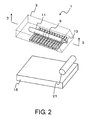
- FIG. 2 is a view showing a bonding head 3 with dotted lines in FIG. 1 :
- FIG. 3 is a side view of FIG. 2 , showing a cross-section of the bonding head 3 taken along line 3 - 3 :
- FIG. 4 is a cross-sectional view of the bonding head 3 taken along line 4 - 4 of FIG. 3 :
- FIG. 5A is a view showing a method attracting a film 17 to the bonding head 3 with use of the film bonding apparatus 1 :
- FIG. 5B is a view showing a method attracting the film 17 to the bonding head 3 with use of the film bonding apparatus 1 :
- FIG. 6A is a view showing a method attracting the film 17 to the bonding head 3 with use of the film bonding apparatus 1 :
- FIG. 6B is a view showing a method attracting the film 17 to the bonding head 3 with use of the film bonding apparatus 1 :
- FIG. 7A is a view showing a method bonding the film 17 onto a glass substrate 19 with use of the film bonding apparatus 1 :
- FIG. 7B is a view showing a method bonding the film 17 onto the glass substrate 19 with use of the film bonding apparatus 1 :
- FIG. 8A is a view showing a method bonding the film 17 onto the glass substrate 19 with use of the film bonding apparatus 1 :
- FIG. 8B is a view showing a method bonding the film 17 onto the glass substrate 19 with use of the film bonding apparatus 1 :
- FIG. 9 is a view showing a display apparatus manufactured by bonding a polarization plate to liquid crystal panels with use of the film bonding apparatus 1 .
- the film bonding apparatus 1 is illustrated as an example of a film bonding apparatus for bonding a film of a flexible polarization film to a bonding object of a glass substrate for a liquid crystal display device.
- the film bonding apparatus 1 as a vacuum suction control mechanism apparatus comprises a bonding head 3 , a bonding surface plate 15 , and a bonding roller 21 as a bonding auxiliary.
- the bonding roller 21 is illustrated as an example of a bonding auxiliary.
- a squeegee bar may be used.
- an end of the bonding head 3 may be used as a squeegee, which serves as a bonding auxiliary.
- the film bonding apparatus 1 includes the bonding head 3 in the form of a block for attracting a film 17 , which will be described later.
- the material of the bonding head 3 is not limited to a specific one. Nevertheless, at least a portion contacting the film 17 is preferably formed of a material comprising elasticity, more preferably rubber or resin comprising a hardness of 20 to 40 by the standard SRIS 0101.
- the bonding head 3 is formed of such a material, bonding pressures are equally generated when the film 17 is bonded onto the glass substrate 19 . Therefore, the glass is prevented from being broken because of local concentration of the bonding pressures, and the thickness of the glass substrate 19 can thus be reduced.
- the bonding head 3 is movable in directions C 1 , C 2 , F 1 , and F 2 of FIG. 3 by an actuator, which is not shown.
- the flat bonding surface plate 15 for holding a bonding object is provided so as to face a surface 3 a of the bonding head 3 .
- the bonding surface plate 15 may be movable in the directions C 1 , C 2 , F 1 , and F 2 of FIG. 3 . Furthermore, the bonding surface plate 15 may comprise a structure for adjusting a ⁇ -direction to adjust the horizontality of the bonding surface plate.
- the material of the bonding surface plate 15 is not limited to a specific one. Nevertheless, the bonding surface plate 15 is preferably formed of a material comprising elasticity, more preferably rubber or resin comprising a hardness of 20 to 40 by the standard SRIS 0101, as with the bonding head 3 .
- the bonding surface plate 15 is formed of such a material, it is possible to attain the same advantages as in the case where the bonding head 3 is formed of such a material.
- cylindrical bonding roller 21 for press the film 17 at the time of bonding is provided so as to face an upper surface 15 a of the bonding surface plate 15 .
- the bonding roller 21 may be rotatable and may be movable in the directions C 1 , C 2 , F 1 , and F 2 of FIG. 3 .
- a space 11 is formed inside of the bonding head 3 .
- a plurality of suction holes 9 are formed in the surface 3 a of the bonding head 3 so as to extend from the surface 3 a to the space 11 .
- a movable piece 5 is provided within the space 11 .
- the movable piece 5 is provided so as to partition the space 11 into a first region 11 a and a second region 11 b .
- the movable piece 5 is movable in contact with the suction holes 9 along directions D 1 and D 2 of FIG. 3 .
- the bonding head 3 comprises a connection portion 13 extending from an inner wall of the first region 11 a to a side surface 3 b of the bonding head 3 .
- a decompression source such as a vacuum pump, which is not shown, is connected to the connection portion 13 .
- a group 9 a of suction holes that communicate with the first region 11 a is connected to the connection portion 13 through the first region 11 a and thus connected to the decompression source.
- the film bonding apparatus 1 connects the suction holes that communicate with the first region 11 a to the decompression source.
- the bonding head 3 is provided such that a predetermined angle of inclination ⁇ is formed between the surface 3 a and the upper surface 15 a of the bonding surface plate 15 . Furthermore, the bonding head 3 is movable in directions E 1 and E 2 . The angle of inclination ⁇ can be changed by this movement.
- Bonding of the film 17 onto the glass substrate 19 with the film bonding apparatus 1 requires a process of attracting the film 17 to the bonding head 3 and a process of bonding the film 17 on the bonding head 3 to the glass substrate 19 .
- the film 17 is first placed and fixed on the bonding surface plate 15 .
- the film 17 has been bonded to a mount 19 a .
- An adhesive layer which is not shown, is provided on a surface of the film 17 that contacts the mount 19 a.
- the film 17 is fixed by vacuum suction or a clamp.
- the bonding head 3 rather than the movable piece 5 , may be moved because the movable piece 5 should only be moved relative to the bonding head 3 .
- the bonding head 3 or the bonding surface plate 15 is moved in the direction C 1 , C 2 , F 1 , or F 2 of FIG. 3 in this state. Furthermore, the bonding head 3 is moved toward the direction E 2 . Thus, as shown in FIG. 5B , all of the suction holes 9 are brought into contact with a surface of the film 17 . Then the decompression source, which is not shown, is operated.
- the position of the film 17 is measured by a sensor, a camera, or the like, which is not shown. Based on the measured position, an actuator, which is not shown, is operated to move the bonding head 3 or the bonding surface plate 15 .
- the suction holes 9 are sequentially brought into communication with the first region 11 a from the rightmost suction hole in FIG. 5B .
- the suction holes 9 are connected to the decompression source in the order in which they have communicated with the first region 11 a . Sequentially, air is exhausted, so that the suction holes 9 attract the film 17 .
- the bonding head 3 and the bonding surface plate 15 may be moved.
- FIG. 6A shows the attraction in progress.
- the group 9 a of the suction holes that communicate with the first region 11 a is connected to the connection portion 13 through the first region 11 a and thus connected to the decompression source. Air in the group 9 a of the suction holes is drawn, so that the group 9 a of the suction holes attracts the film 17 .
- the suction force depends upon the surface roughness and the flexibility of the film 17 .
- the bonding head 3 is inclined toward the direction E 1 of FIG. 3 to the original angle of inclination ⁇ (see FIG. 3 ).
- the bonding head 3 or the bonding surface plate 15 is moved in the directions C 1 , C 2 , F 1 , and F 2 of FIG. 3 so as to separate the bonding head 3 from the bonding surface plate 15 .
- the suction holes are connected to the decompression source in the order in which they have communicated with the first region 11 a , thereby attracting the film 17 .
- the film 17 can be attracted with accuracy without deviation of the film 17 at the time of attraction.
- the glass substrate 19 is fixed on the bonding surface plate 15 .
- the same fixing member fixing the film 17 may be used.
- the bonding head 3 that has attracted the film 17 or the bonding surface plate 15 is moved in the directions C 1 , C 2 , F 1 , and F 2 of FIG. 3 so that the right end of the film 17 is brought into contact with a desired location of the glass substrate 19 .
- the right end of the film 17 is pressed by the bonding roller 21 .
- the desired location of the glass substrate 19 is measured by a sensor, a camera, or the like, which is not shown. Based on the measured location, an actuator, which is not shown, is operated to move the bonding head 3 or the bonding surface plate 15 .
- the bonding surface plate 15 is moved toward the direction C 1 . Furthermore, the movable piece 5 is moved toward the direction D 1 of FIG. 7A in synchronism with the movement of the bonding surface plate 15 .
- the bonding head 3 and the bonding roller 21 are not moved.
- the film 17 is bonded to the glass substrate 19 from its right end by the pressure of the bonding roller 21 . At that time, communications of the suction holes 9 with the first region 11 a are sequentially cut off from the leftmost suction hole, and those suction holes 9 lose a suction force.
- the film 17 moves on the surface of the bonding head 3 toward the direction D 1 with maintaining a tension in a state such that the film 17 has been attracted to the surface of the bonding head 3 , the film 17 is bonded to the glass substrate 19 .
- FIGS. 7B and 8A show the bonding in progress.
- a group 9 a of the suction holes that has communicated with the first region 11 a is connected to the connection portion 13 through the first region 11 a , so that those suction holes attract the film 17 .
- the film 17 is bonded to the glass substrate 19 , and a liquid crystal panel is completed.
- FIG. 9 shows a display apparatus 27 manufactured by bonding a polarization plate to liquid crystal panels with use of the film bonding apparatus 1 .
- a polarization plate 25 is bonded to liquid crystal panels 26 with use of the film bonding apparatus 1 .
- the movable piece 5 is moved so that the suction holes 9 lose a suction force sequentially from the leftmost suction hole.
- the film 17 is bonded to the glass substrate 19 while it moves on the surface of the bonding head 3 toward the direction D 1 in a state such that the film 17 has been attracted to the surface 3 a of the bonding head 3 .
- the film 17 can be bonded with accuracy.
- the film bonding apparatus 1 includes a bonding head 3 comprising a plurality of suction holes and a space 11 defined therein and a movable piece 5 for partitioning the space 11 into two regions.
- the suction holes 9 that communicate with a first region 11 a are connected to or disconnected from a decompression source.
- the film bonding apparatus 1 does not require a plurality of valves for suction control.
- the film bonding apparatus 1 comprises a simple structure.
- the film 17 can be bonded with accuracy.
- the film bonding apparatus 1 when used to bond the film 17 onto the glass substrate 19 for manufacturing a display apparatus, the quality of the manufactured display apparatus can be improved.
- a film bonding apparatus 1 shown in FIG. 1 was prepared.
- a polarization film was bonded to a glass substrate 19 comprising a diagonal of 2 inches to 60 inches.
- the polarization film used for bonding had a surface roughness such that 0.3 ⁇ m ⁇ Ra ⁇ 3.0 ⁇ m.
- the thickness of the polarization film was in a range of from 0.1 mm to 0.5 mm.
- a suction force of each suction hole at the time of a bonding was set in a range of from about 2.0 ⁇ 10 4 Pa to about 4.9 ⁇ 10 4 Pa.
- the present invention is applied to an apparatus for bonding a polarization film to a liquid crystal display substrate.
- the present invention is not limited to that example and is applicable to any apparatus for bonding a film to a bonding object.
- the movable piece may be movable relative to the bonding head at the time of bonding.
- the bonding head may be movable relative to the movable piece at the time of bonding.
- the vacuum suction control mechanism may further comprise a bonding surface plate for holding a bonding object, and a relative position between the bonding head and the bonding surface plate can be changed.
- the relative position may be changed by movement of the bonding head or the bonding surface plate.
- the bonding head and/or the bonding surface plate may comprise elasticity.
- the vacuum suction control mechanism apparatus may further comprise an auxiliary provided so as to face the bonding surface plate for pressing the film at the time of bonding.
- the auxiliary may comprise a rotatable bonding roller or a squeegee bar.
- the film may comprise flexibility.
- the film may be an optical film
- the bonding object may be a substrate that allows visible light to pass therethrough.
- the optical film may be a polarization film
- the display apparatus may be a liquid crystal display apparatus.
- the bonding object may be formed of glass.
- the vacuum suction control mechanism apparatus comprises a movable piece for partitioning a space defined in the bonding head into two regions. Only the suction holes that communicate with a first region, which is one of the regions partitioned by the movable piece, comprise a suction force.
- attraction can be controlled merely by movement of the movable piece.
- a film can accurately be bonded to a bonding object with a simple structure without deviation of the film or mixing of dust or air.
- a display apparatus according to an embodiment of the present invention is manufactured by using a vacuum suction control mechanism apparatus according to the present invention, the quality of the display apparatus can be improved.
Landscapes
- Engineering & Computer Science (AREA)
- Physics & Mathematics (AREA)
- Nonlinear Science (AREA)
- Manufacturing & Machinery (AREA)
- Chemical & Material Sciences (AREA)
- Crystallography & Structural Chemistry (AREA)
- Quality & Reliability (AREA)
- Textile Engineering (AREA)
- General Physics & Mathematics (AREA)
- Optics & Photonics (AREA)
- Liquid Crystal (AREA)
- Labeling Devices (AREA)
- Adhesive Tape Dispensing Devices (AREA)
- Polarising Elements (AREA)
Abstract
Description
- 1 Film bonding apparatus
- 3 Bonding head
- 5 Movable piece
- 9 Suction hole
- 9 a Group of suction holes
- 11 a First region
- 11 b Second region
- 13 Connection portion
- 15 Bonding surface plate
- 15 a Upper surface
- 17 Film
- 19 Glass substrate
- 19 a Mount
- 21 Bonding roller
- 25 Polarization plate
- 26 Liquid crystal panel
- 27 Display apparatus
Claims (21)
Applications Claiming Priority (3)
| Application Number | Priority Date | Filing Date | Title |
|---|---|---|---|
| JP2007-229159 | 2007-09-04 | ||
| JP2007229159A JP5151326B2 (en) | 2007-09-04 | 2007-09-04 | Vacuum adsorption control mechanism device, film sticking device, display device |
| PCT/JP2008/065226 WO2009031440A1 (en) | 2007-09-04 | 2008-08-20 | Vacuum adsorption control mechanism device, film applying device, and display device |
Publications (2)
| Publication Number | Publication Date |
|---|---|
| US20100214504A1 US20100214504A1 (en) | 2010-08-26 |
| US8767138B2 true US8767138B2 (en) | 2014-07-01 |
Family
ID=40428761
Family Applications (1)
| Application Number | Title | Priority Date | Filing Date |
|---|---|---|---|
| US12/675,858 Active 2029-03-27 US8767138B2 (en) | 2007-09-04 | 2008-08-20 | Vacuum adsorption control mechanism device, film applying device, and display device |
Country Status (6)
| Country | Link |
|---|---|
| US (1) | US8767138B2 (en) |
| JP (1) | JP5151326B2 (en) |
| KR (1) | KR101267625B1 (en) |
| CN (1) | CN101795849B (en) |
| TW (1) | TWI410323B (en) |
| WO (1) | WO2009031440A1 (en) |
Families Citing this family (9)
| Publication number | Priority date | Publication date | Assignee | Title |
|---|---|---|---|---|
| KR101550486B1 (en) * | 2011-08-05 | 2015-09-04 | 주식회사 엘지화학 | Attaching Device |
| TWI463180B (en) * | 2012-03-30 | 2014-12-01 | Au Optronics Corp | Attaching method for a stereo imaging film and attaching apparatus for the same |
| US8951373B2 (en) * | 2012-05-07 | 2015-02-10 | Sony Corporation | Replaceable protective layer on flat screen display |
| TW201540611A (en) * | 2014-04-23 | 2015-11-01 | Beac Co Ltd | Member attaching device |
| CN104691086B (en) | 2015-03-30 | 2017-02-01 | 小米科技有限责任公司 | Attachment control system, method and device |
| JP2018111207A (en) * | 2015-05-20 | 2018-07-19 | 長野オートメーション株式会社 | Device for pasting film |
| CN108724689B (en) * | 2018-05-10 | 2020-01-17 | 深圳市志凌伟业技术股份有限公司 | Large-size laminating machine |
| CN109720621B (en) * | 2018-12-29 | 2021-10-22 | 贾瑞霞 | Vegetable bundling machine for vegetable processing capable of improving stability by negative-pressure electrostatic adsorption |
| CN113910735B (en) * | 2020-07-08 | 2023-12-08 | 厦门巨锐自动化设备有限公司 | Test paper pad pasting equipment |
Citations (4)
| Publication number | Priority date | Publication date | Assignee | Title |
|---|---|---|---|---|
| JPH1034476A (en) | 1996-07-18 | 1998-02-10 | Nec Eng Ltd | Sheet sticking device |
| JP2001042315A (en) | 1999-08-04 | 2001-02-16 | Nec Eng Ltd | Film sticking device for liquid crystal display element and film sticking method for liquid crystal display element |
| JP2003019755A (en) | 2001-07-09 | 2003-01-21 | Lintec Corp | Laminating device and method |
| JP2006159488A (en) | 2004-12-03 | 2006-06-22 | Daiichi Seiko Kk | Film sticking apparatus and film sticking method |
Family Cites Families (1)
| Publication number | Priority date | Publication date | Assignee | Title |
|---|---|---|---|---|
| JP4780559B2 (en) * | 2005-12-14 | 2011-09-28 | 株式会社日立プラントテクノロジー | Film sticking method and apparatus |
-
2007
- 2007-09-04 JP JP2007229159A patent/JP5151326B2/en active Active
-
2008
- 2008-08-20 KR KR1020107003817A patent/KR101267625B1/en not_active Expired - Fee Related
- 2008-08-20 WO PCT/JP2008/065226 patent/WO2009031440A1/en not_active Ceased
- 2008-08-20 US US12/675,858 patent/US8767138B2/en active Active
- 2008-08-20 CN CN200880105023.1A patent/CN101795849B/en active Active
- 2008-08-28 TW TW097132894A patent/TWI410323B/en not_active IP Right Cessation
Patent Citations (4)
| Publication number | Priority date | Publication date | Assignee | Title |
|---|---|---|---|---|
| JPH1034476A (en) | 1996-07-18 | 1998-02-10 | Nec Eng Ltd | Sheet sticking device |
| JP2001042315A (en) | 1999-08-04 | 2001-02-16 | Nec Eng Ltd | Film sticking device for liquid crystal display element and film sticking method for liquid crystal display element |
| JP2003019755A (en) | 2001-07-09 | 2003-01-21 | Lintec Corp | Laminating device and method |
| JP2006159488A (en) | 2004-12-03 | 2006-06-22 | Daiichi Seiko Kk | Film sticking apparatus and film sticking method |
Non-Patent Citations (3)
| Title |
|---|
| International Search Report, PCT/JP2008/065226, Oct. 21, 2008. |
| Machine translation of JP 10-034476 A. * |
| Taiwanese Office Action with Search Report dated Dec. 8, 2011. |
Also Published As
| Publication number | Publication date |
|---|---|
| KR20100046023A (en) | 2010-05-04 |
| CN101795849B (en) | 2013-05-29 |
| KR101267625B1 (en) | 2013-05-24 |
| US20100214504A1 (en) | 2010-08-26 |
| TW200925727A (en) | 2009-06-16 |
| CN101795849A (en) | 2010-08-04 |
| JP5151326B2 (en) | 2013-02-27 |
| TWI410323B (en) | 2013-10-01 |
| WO2009031440A1 (en) | 2009-03-12 |
| JP2009062108A (en) | 2009-03-26 |
Similar Documents
| Publication | Publication Date | Title |
|---|---|---|
| US8887781B2 (en) | Vacuum adsorption control mechanism device, film pasting device, method of pasting film, and display device | |
| US8767138B2 (en) | Vacuum adsorption control mechanism device, film applying device, and display device | |
| TWI266104B (en) | Manufacturing method of liquid crystal display apparatus and substrate assembling apparatus | |
| JP4098705B2 (en) | Substrate bonding apparatus for liquid crystal display element manufacturing process | |
| CN116043181B (en) | Film forming device and method for manufacturing organic EL display device using the same | |
| KR20150108481A (en) | Lamination apparatus and lamination method | |
| KR20150113397A (en) | Apparatus and Method of Bonding Flexible Display and Curved Cover Element | |
| WO2006046379A1 (en) | Adhesive chuck device | |
| TW200823535A (en) | Apparatus for attaching substrates | |
| CN100381885C (en) | Loader and joining device for manufacturing liquid crystal display devices and loading method thereof | |
| JP4482395B2 (en) | Substrate bonding method and bonding apparatus | |
| JP3819797B2 (en) | Board assembly equipment | |
| KR100994494B1 (en) | Board Bonding Device | |
| JP4589270B2 (en) | Substrate bonding device for liquid crystal display elements | |
| JP4449923B2 (en) | Substrate assembly method and apparatus | |
| KR101404057B1 (en) | Laminating Device and Method for Apparatus of Bonding Substrates, and Apparatus and Method of Bonding Substrates Having the same | |
| KR20140085235A (en) | Apparatus for attaching substrates | |
| KR20200042692A (en) | A suction jig for roll lamination using psc | |
| JP3848942B2 (en) | Substrate assembly method and apparatus | |
| JP2008216695A (en) | Liquid crystal element manufacturing apparatus, liquid crystal element, and light deflection element | |
| US20090133801A1 (en) | Substrate attaching apparatus | |
| KR102416236B1 (en) | Multi chuck fixing panel and display lamination apparatus using the same | |
| KR100913219B1 (en) | Board Bonding Device and Board Bonding Method | |
| JP4751659B2 (en) | Substrate bonding device | |
| KR20220158624A (en) | Substrate Holding Unit, Substrate Holding Apparatus, Film-Forming System and Method for Manufacturing Electronic Device |
Legal Events
| Date | Code | Title | Description |
|---|---|---|---|
| AS | Assignment |
Owner name: NEC LCD TECHNOLOGIES, LTD., JAPAN Free format text: ASSIGNMENT OF ASSIGNORS INTEREST;ASSIGNOR:KODERA, HIDEKI;REEL/FRAME:024159/0798 Effective date: 20100304 |
|
| AS | Assignment |
Owner name: NLT TECHNOLOGIES, LTD., JAPAN Free format text: CHANGE OF NAME;ASSIGNOR:NEC LCD TECHNOLOGIES, LTD.;REEL/FRAME:027190/0060 Effective date: 20110701 |
|
| STCF | Information on status: patent grant |
Free format text: PATENTED CASE |
|
| FEPP | Fee payment procedure |
Free format text: PAYOR NUMBER ASSIGNED (ORIGINAL EVENT CODE: ASPN); ENTITY STATUS OF PATENT OWNER: LARGE ENTITY |
|
| MAFP | Maintenance fee payment |
Free format text: PAYMENT OF MAINTENANCE FEE, 4TH YEAR, LARGE ENTITY (ORIGINAL EVENT CODE: M1551) Year of fee payment: 4 |
|
| AS | Assignment |
Owner name: TIANMA JAPAN, LTD., JAPAN Free format text: CHANGE OF NAME;ASSIGNOR:NLT TECHNOLOGIES, LTD.;REEL/FRAME:049188/0536 Effective date: 20170703 |
|
| AS | Assignment |
Owner name: TIANMA MICRO-ELECTRONICS CO., LTD., CHINA Free format text: ASSIGNMENT OF ASSIGNORS INTEREST;ASSIGNOR:TIANMA JAPAN, LTD.;REEL/FRAME:049203/0605 Effective date: 20190507 |
|
| AS | Assignment |
Owner name: SHENZHEN TECHVISUM TECHNOLOGIES LIMITED, CHINA Free format text: ASSIGNMENT OF ASSIGNORS INTEREST;ASSIGNOR:TIANMA MICRO-ELECTRONICS CO., LTD.;REEL/FRAME:049644/0278 Effective date: 20190617 |
|
| AS | Assignment |
Owner name: BEIHAI HUIKE PHOTOELECTRIC TECHNOLOGY CO., LTD., C Free format text: ASSIGNMENT OF ASSIGNORS INTEREST;ASSIGNOR:SHENZHEN TECHVISUM TECHNOLOGIES LIMITED;REEL/FRAME:049675/0165 Effective date: 20190621 |
|
| AS | Assignment |
Owner name: BEIHAI HKC OPTOELECTRONICS TECHNOLOGY CO., LTD., C Free format text: CORRECTIVE ASSIGNMENT TO CORRECT THE RECEIVING PARTY NAME AND ADDRESS PREVIOUSLY RECORDED AT REEL: 49675 FRAME: 165. ASSIGNOR(S) HEREBY CONFIRMS THE ASSIGNMENT;ASSIGNOR:SHENZHEN TECHVISUM TECHNOLOGIES LIMITED;REEL/FRAME:050347/0537 Effective date: 20190621 |
|
| MAFP | Maintenance fee payment |
Free format text: PAYMENT OF MAINTENANCE FEE, 8TH YEAR, LARGE ENTITY (ORIGINAL EVENT CODE: M1552); ENTITY STATUS OF PATENT OWNER: LARGE ENTITY Year of fee payment: 8 |
|
| MAFP | Maintenance fee payment |
Free format text: PAYMENT OF MAINTENANCE FEE, 12TH YEAR, LARGE ENTITY (ORIGINAL EVENT CODE: M1553); ENTITY STATUS OF PATENT OWNER: LARGE ENTITY Year of fee payment: 12 |