US8744116B2 - Magnetic circuit for speaker and speaker using same - Google Patents
Magnetic circuit for speaker and speaker using same Download PDFInfo
- Publication number
- US8744116B2 US8744116B2 US13/823,762 US201113823762A US8744116B2 US 8744116 B2 US8744116 B2 US 8744116B2 US 201113823762 A US201113823762 A US 201113823762A US 8744116 B2 US8744116 B2 US 8744116B2
- Authority
- US
- United States
- Prior art keywords
- bond magnet
- magnetic
- yoke
- upper section
- magnetic circuit
- Prior art date
- Legal status (The legal status is an assumption and is not a legal conclusion. Google has not performed a legal analysis and makes no representation as to the accuracy of the status listed.)
- Active
Links
- 238000001746 injection moulding Methods 0.000 claims description 9
- 230000005389 magnetism Effects 0.000 abstract description 10
- 230000004907 flux Effects 0.000 description 42
- 239000006247 magnetic powder Substances 0.000 description 33
- 229920005989 resin Polymers 0.000 description 25
- 239000011347 resin Substances 0.000 description 25
- 239000000696 magnetic material Substances 0.000 description 20
- 239000000463 material Substances 0.000 description 19
- 238000004519 manufacturing process Methods 0.000 description 11
- 230000002349 favourable effect Effects 0.000 description 7
- 230000002093 peripheral effect Effects 0.000 description 6
- 238000010586 diagram Methods 0.000 description 5
- 239000000428 dust Substances 0.000 description 5
- 238000000465 moulding Methods 0.000 description 5
- 239000013585 weight reducing agent Substances 0.000 description 5
- 239000000853 adhesive Substances 0.000 description 4
- 238000009826 distribution Methods 0.000 description 3
- CURLTUGMZLYLDI-UHFFFAOYSA-N Carbon dioxide Chemical compound O=C=O CURLTUGMZLYLDI-UHFFFAOYSA-N 0.000 description 2
- 230000001070 adhesive effect Effects 0.000 description 2
- 230000003064 anti-oxidating effect Effects 0.000 description 2
- 238000005336 cracking Methods 0.000 description 2
- 238000000034 method Methods 0.000 description 2
- 239000000203 mixture Substances 0.000 description 2
- 239000003208 petroleum Substances 0.000 description 2
- 229920002647 polyamide Polymers 0.000 description 2
- -1 polypropylene Polymers 0.000 description 2
- 229920005992 thermoplastic resin Polymers 0.000 description 2
- 239000004952 Polyamide Substances 0.000 description 1
- 239000004698 Polyethylene Substances 0.000 description 1
- 239000004734 Polyphenylene sulfide Substances 0.000 description 1
- 239000004743 Polypropylene Substances 0.000 description 1
- 239000004372 Polyvinyl alcohol Substances 0.000 description 1
- 230000001154 acute effect Effects 0.000 description 1
- 150000001336 alkenes Chemical class 0.000 description 1
- 229910000828 alnico Inorganic materials 0.000 description 1
- 229910002092 carbon dioxide Inorganic materials 0.000 description 1
- 239000001569 carbon dioxide Substances 0.000 description 1
- 239000003795 chemical substances by application Substances 0.000 description 1
- 238000000748 compression moulding Methods 0.000 description 1
- 230000008602 contraction Effects 0.000 description 1
- 230000008878 coupling Effects 0.000 description 1
- 238000010168 coupling process Methods 0.000 description 1
- 238000005859 coupling reaction Methods 0.000 description 1
- 230000007423 decrease Effects 0.000 description 1
- 230000006866 deterioration Effects 0.000 description 1
- 229920001971 elastomer Polymers 0.000 description 1
- 239000000806 elastomer Substances 0.000 description 1
- 150000002148 esters Chemical class 0.000 description 1
- 238000001125 extrusion Methods 0.000 description 1
- 239000004744 fabric Substances 0.000 description 1
- 239000000446 fuel Substances 0.000 description 1
- 238000009434 installation Methods 0.000 description 1
- 239000000314 lubricant Substances 0.000 description 1
- 230000005415 magnetization Effects 0.000 description 1
- 239000002184 metal Substances 0.000 description 1
- 229910052751 metal Inorganic materials 0.000 description 1
- 239000007769 metal material Substances 0.000 description 1
- 150000002739 metals Chemical class 0.000 description 1
- 229910001172 neodymium magnet Inorganic materials 0.000 description 1
- JRZJOMJEPLMPRA-UHFFFAOYSA-N olefin Natural products CCCCCCCC=C JRZJOMJEPLMPRA-UHFFFAOYSA-N 0.000 description 1
- 239000004417 polycarbonate Substances 0.000 description 1
- 229920000515 polycarbonate Polymers 0.000 description 1
- 229920000728 polyester Polymers 0.000 description 1
- 229920000573 polyethylene Polymers 0.000 description 1
- 229920000069 polyphenylene sulfide Polymers 0.000 description 1
- 229920001155 polypropylene Polymers 0.000 description 1
- 229920002451 polyvinyl alcohol Polymers 0.000 description 1
- 229920000915 polyvinyl chloride Polymers 0.000 description 1
- 239000004800 polyvinyl chloride Substances 0.000 description 1
- 238000004064 recycling Methods 0.000 description 1
- 229920002725 thermoplastic elastomer Polymers 0.000 description 1
- 238000010792 warming Methods 0.000 description 1
- 229910000859 α-Fe Inorganic materials 0.000 description 1
Images


Classifications
-
- H—ELECTRICITY
- H04—ELECTRIC COMMUNICATION TECHNIQUE
- H04R—LOUDSPEAKERS, MICROPHONES, GRAMOPHONE PICK-UPS OR LIKE ACOUSTIC ELECTROMECHANICAL TRANSDUCERS; DEAF-AID SETS; PUBLIC ADDRESS SYSTEMS
- H04R3/00—Circuits for transducers, loudspeakers or microphones
-
- H—ELECTRICITY
- H04—ELECTRIC COMMUNICATION TECHNIQUE
- H04R—LOUDSPEAKERS, MICROPHONES, GRAMOPHONE PICK-UPS OR LIKE ACOUSTIC ELECTROMECHANICAL TRANSDUCERS; DEAF-AID SETS; PUBLIC ADDRESS SYSTEMS
- H04R9/00—Transducers of moving-coil, moving-strip, or moving-wire type
- H04R9/02—Details
- H04R9/025—Magnetic circuit
Definitions
- a cavity of a mold for conventional bond magnet 103 is made of a non-magnetic material, and in the shape of bond magnet 103 . Further, bond magnet 103 is formed by filling the cavity with a resin containing magnetic powder.
- a face of the cavity corresponding to upper section of side surface 103 B is provided as an annular magnetic body.
- the annular magnetic body is provided with a hole having a shape of upper section of side surface 103 B, and upper section of side surface 103 B is formed by an inner face of the hole in the annular magnetic body.
- a stick-shaped magnetic body is provided at a position corresponding to through hole 103 A, and through hole 103 A is formed by this second magnetic body. Then, the magnetic orientation of bond magnet 103 is achieved by causing magnetism to pass from the stick-shaped magnetic body toward the annular magnetic body when molding.
- conventional bond magnet 103 includes through hole 103 A.
- magnetism characteristic magnetic flux density in the magnetic gap
- a magnetic circuit using conventional bond magnet 103 has problems that it is difficult to downsize or thin speakers and that the weight of the speakers increases.
- a magnetic circuit for a speaker provided according to the present invention in order to solve the above problems is configured such that a bond magnet has anisotropy, and that a magnetic field is oriented from a lower side surface of the bond magnet and toward an upper section of side surface of the bond magnet. Further, the bond magnet is configured such that the upper section of side surface of the bond magnet is disposed closer to an inner surface of an outer periphery of a yoke than the lower side surface of the bond magnet is, and that the upper section of side surface of the bond magnet faces against the yoke side surface.
- FIG. 2 is a top view of the magnetic circuit for a speaker.
- FIG. 5B is a cross-sectional view of a magnetic circuit for a speaker according to a third example of the first exemplary embodiment of the present invention.
- FIG. 5C is a cross-sectional view of a magnetic circuit for a speaker according to a fourth example of the first exemplary embodiment of the present invention.
- FIG. 6A is a top view of a magnetic circuit for a speaker according to a fifth example of the first exemplary embodiment of the present invention.
- FIG. 9 is a conceptual diagram illustrating a flow of a magnetic flux of the magnetic circuit for a speaker.
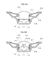
- FIG. 10A is a cross-sectional view of a speaker according to a third exemplary embodiment of the present invention.
- FIG. 10B is a cross-sectional view of a speaker according to a second example of the third exemplary embodiment.
- Yoke 12 includes yoke bottom 12 A, and yoke side surface 12 B provided upright for yoke bottom 12 A.
- Bond magnet 11 is fixed on yoke bottom 12 A.
- Magnetic gap 14 is provided between upper section of side surface 11 B of bond magnet 11 and an inner surface of yoke side surface 12 B.
- First connecting section 11 C connects lowest edge of side surface 11 A with upper section of side surface 11 B.
- bond magnet 11 has magnetic anisotropy in this orientation. With such a configuration, the magnetic flux can be efficiently converged at the gap portion without providing a plate on an upper portion of bond magnet 11 . Accordingly, it is possible to realize the magnetic circuit with only two pieces of components, and thus lead to increased productivity.
- a cross-sectional shape of bond magnet 11 is configured such that upper section of side surface 11 B has a greater diameter than that of bottom surface 11 D, and the connecting section connecting upper section of side surface 11 B with lowest edge of side surface 11 A is inclined with respect to yoke bottom 12 A. Further, upper section of side surface 11 B faces against yoke side surface 12 B.
- a cross-sectional shape is referred to as a quasi trapezoid.
- bond magnet 11 is disposed in a manner that the side of bottom surface 11 D of bond magnet 11 faces toward the side of yoke bottom 12 A.
- a cross-sectional shape of bond magnet 11 when disposed in such a manner is referred to as an inverted trapezoidal shape.
- the magnetism may not leak to yoke bottom 12 A from a portion of first connecting section 11 C near yoke bottom 12 A or lowest edge of side surface 11 A. Therefore, generation of a magnetic flux loss does not increase even if first connecting section 11 C is inclined to yoke bottom 12 A, and it is possible to achieve bond magnet 11 having a favorable magnetism characteristic.
- the shape of magnetic powder 52 used in the material according to this exemplary embodiment is polyhedral or polygonal plate-like. Therefore, an area in which resin 51 is in contact with magnetic powder 52 becomes large, and therefore an adhesive strength with resin 51 can be increased. With this, it is possible to make it less susceptible to cracking and such due to a drop impact.
- upper section of side surface 11 B of bond magnet 11 is less susceptible to deformation of the shape due to dropping and such, and therefore it is possible to make the magnetic force on upper section of side surface 11 B even.
- magnetic powder 52 according to this exemplary embodiment is uneven.
- magnetic powder 52 of so-called quasi infinite form is used for bond magnet 11 .
- an internal loss of bond magnet 11 can be increased in a wide range of vibration frequencies. Therefore, as it is possible to make resonance due to vibration of diaphragm 27 that will be later described less likely to occur, magnetic circuit 13 that is able to reproduce high-quality sound can be achieved.
- magnetic powder 52 having a grain diameter of 400 ⁇ m or smaller be used.
- magnetic powder whose average grain diameter is from 1 ⁇ m to 400 ⁇ m is used as magnetic powder 52 according to this exemplary embodiment.
- bond magnet 11 contains magnetic powder 52 of various sizes mixed therein.
- the internal loss of bond magnet 11 can be increased in a wide range of vibration frequencies. Therefore, as it is possible to make the resonance due to vibration of diaphragm 27 that will be later described less likely to occur, magnetic circuit 13 that is able to reproduce high-quality sound can be achieved.
- magnetic powder 52 whose grain size distribution is from 1 ⁇ m to 30 ⁇ m.
- magnetic powder 52 whose grain diameter and grain size distribution are small, it is possible to increase a filling rate of magnetic powder 52 in resin 51 .
- magnetic powder 52 can be distributed evenly in resin 51 . With this, it is possible to realize bond magnet 11 having favorable orientation of the magnetic powder.
- magnetic powder 52 is less susceptible to contraction in injection molding. Therefore, it is possible to make shape stability of bond magnet 11 favorable (size variation is reduced) by filling a large amount of such magnetic powder 52 . With this, as an interval of magnetic gap 14 can be reduced, the magnetic flux density in magnetic gap 14 can be increased.
- a material of resin 51 that constitutes bond magnet 11 is not particularly limited as long as it is made of a thermoplastic resin material.
- a thermoplastic resin materials such as polypropylene, polyethylene, polyvinyl chloride, polyester, polyamide, polycarbonate, polyvinyl alcohol, and polyphenylene sulfide can be used, for example.
- a thermoplastic elastomer materials such as olefin based, ester based, and polyamide based can be used, for example.
- the resin or the elastomer can be made of a single material or of a mixture of two or more materials.
- the resin for bond magnet 11 As the resin for bond magnet 11 according to this exemplary embodiment, a virgin material is used. However, the resin for bond magnet 11 can be partly or entirely made of a recycled resin. With this, it is possible to reduce a consumed amount of petroleum resources. Therefore, as reduction of depletion of petroleum resources and carbon dioxide emissions can be realized, it is possible to protect the global environment.
- antioxidizing agent may be added.
- first connecting section 11 C is in a circular arc cross-sectional shape. With this, as the distance between the magnetic poles of bond magnet 11 increases, the permeance coefficient increases and a value of the magnetic flux density also increases. With this, it is possible to further improve the magnetic efficiency, and reduce the required cubic volume and weight.
- first connecting section 11 C is curved in a direction of the recess. With this, it becomes easier to make the orientation of the magnetic field at upper section of side surface 11 B perpendicular to upper section of side surface 11 B and yoke side surface 12 B. Therefore, as the magnetic flux can be converged to upper section of side surface 11 B, and to magnetic gap 14 , it is possible to reduce the cubic volume, as well as the weight, of bond magnet 11 without reducing the magnetic flux density at magnetic gap 14 .
- first connecting section 11 C is not limited to the shape according to this example, and can be in a different shape such as a linear shape.
- FIG. 5A is a cross-sectional view of the magnetic circuit for a speaker having a first connecting section according to a second example
- FIG. 5B is a cross-sectional view of the magnetic circuit for a speaker having a first connecting section according to a third example
- FIG. 5C is a cross-sectional view of the magnetic circuit for a speaker having a second connecting section according to a fourth example.
- first connecting section 11 C in the second, the third, or the fourth example is linear, and this is a difference from first connecting section 11 C according to the first example.
- first connecting section 11 C in a linear shape as in the second and the third examples, it is possible to facilitate manufacturing of a mold, and thus to reduce the cost for the mold.
- first connecting section 11 C in the second example is different from first connecting section 11 C in the third example in that first connecting section 11 C in the second example includes a bent portion.
- the bent portion has a shape such that the bent portion is flexed toward a direction of the recess in its cross-section. With this, it becomes easier to make the orientation of the magnetic field at upper section of side surface 11 B perpendicular to upper section of side surface 11 B and yoke side surface 12 B. Therefore, as the magnetic flux can be converged to upper section of side surface 11 B, and to magnetic gap 14 , it is possible to reduce the cubic volume, as well as the weight, of bond magnet 11 without reducing the magnetic flux density at magnetic gap 14 .
- first connecting section 11 C in the fourth example is different from first connecting section 11 C in the second example in that first connecting section 11 C in the fourth example is perpendicular to yoke bottom 12 A and that an angle of the bent portion is 90 degrees.
- first connecting section 11 C also functions as second connecting section 11 E.
- bond magnet 11 is described in this example, the shape of bond magnet 11 according to the present invention is not limited to such an example, and can be polygonal, ellipsoidal, track-shaped, rectangular, or the like. In the following, cases to which bond magnet 11 according to the present invention is applied are used to magnetic circuit 13 of representative shapes.
- FIG. 6A is a top view of a magnetic circuit for a speaker according to a fifth example
- FIG. 6B is a top view of a magnetic circuit for a speaker according to a sixth example.
- bond magnet 11 and yoke bottom 12 A are both track-shaped.
- bond magnet 11 and yoke bottom 12 A are both rectangular.
- FIG. 7 is a manufacturing apparatus used for manufacturing bond magnet 11 according to this exemplary embodiment.
- Bond magnet 11 according to this exemplary embodiment is provided by injection molding a mixed material of a resin, magnetic powder, and such.
- the manufacturing apparatus for manufacturing bond magnet 11 performs injection molding of the mixed material of a resin, magnetic powder, and such into cavity 6 .
- cavity 6 has a shape (of bond magnet 11 ) such that its cross-section is in an inverted trapezoidal shape.
- a wall surface of cavity 6 is made of non-magnetic material 3 .
- an upper surface of cavity 6 is defined by upper non-magnetic material 3 A, and surfaces corresponding to lowest edge of side surface 11 A, first connecting section 11 C, and second connecting section 11 E are defined by lower non-magnetic material 3 B.
- Lower non-magnetic material 3 B is disposed on lower magnetic material 4 , and a side surface of lower magnetic material 4 is exposed from the lower non-magnetic material.
- lower magnetic material 4 includes projection 4 A, and projection 4 A is enclosed by non-magnetic material 3 B. However, a tip end of projection 4 A is exposed at a portion corresponding to bottom surface 11 D of bond magnet 11 within an inner wall of cavity 6 .
- Outer peripheral magnetic material 5 is disposed between upper non-magnetic material 3 A and lower non-magnetic material 3 B, and outer peripheral magnetic material 5 includes a hole for forming side walls. Then, by exposing an inner periphery of hole for forming side walls to the inner wall of cavity 6 , a surface corresponding to upper section of side surface 11 B is provided for cavity 6 .
- Coil 2 is provided so as to form a magnetic field within cavity 6 , and disposed so as to enclose an exposed portion of lower magnetic material 4 . Then, by supplying a current to coil 2 , a magnetic field is generated in a vertical direction (from upside toward downside in FIG. 7 ). Further, as lower magnetic material 4 and outer peripheral magnetic material 5 are magnetic bodies, the magnetic field generated by coil 2 flows within cavity 6 following the shape of cavity 6 (first connecting section 11 C and second connecting section 11 E). With this, it is possible to achieve orientation of the magnetic field directed from an upper surface of the projection toward hole for forming side walls 5 A of outer peripheral magnetic material 5 within cavity 6 .
- the magnetic field is efficiently oriented within cavity 6 by the magnetic field generated by coil 2 being directed from outer peripheral magnetic material 5 back toward lower magnetic material 4 via pole 7 A of the magnetic body and base portion 7 B of the magnetic body.
- the magnetic field generated by energized coil 2 the magnetic field is generated within cavity 6 such that the magnetic field is directed from the upper surface of projection 4 A toward the inner surface of hole for forming side walls 5 A (see an arrow in FIG. 7 ).
- resin molding the mixed material of the resin and the magnetic powder in such a magnetic field it is possible to make an easy axis of magnetization of bond magnet 11 oriented in a direction of a magnetic line generated within cavity 6 .
- bond magnet 11 whose magnetic field is oriented from lowest edge of side surface 11 A toward upper section of side surface 11 B as illustrated in FIG. 3 (as shown by an arrow in FIG. 3 ) can be provided.
- first connecting section 11 C As in the cases from the first to the third examples, it is possible to make flowability of the resin favorable, and to ensure the orientation of the magnetic field. Furthermore, as in the case of the fourth example, R may be provided at the bent portion of first connecting section 11 C. With this, it is possible to make flowability of the resin favorable, and the orientation of the magnetic field can be further ensured.
- the molding method is not particularly limited, and extrusion molding, compression molding, or injection molding can be employed, for example. It should be noted that it is particularly preferable that the molding be performed by injection molding in terms of productivity and easiness in installation of orientation facilities.
- yoke 12 and bond magnet 11 can be molded integrally by preliminarily placing yoke 12 within the cavity of the mold.
- yoke side surface 12 B is not provided along a short side of yoke 12 .
- yoke 12 is provided with a magnetic field directed from the outer periphery along a long side of yoke 12 toward the center. With this, the magnetic field generated by coil 2 may not flow to yoke 12 , but flows within cavity 6 . Therefore, the bond magnet and the yoke can be joined without using an adhesive agent, and it is possible to achieve magnetic circuit 13 with higher productivity.
- FIG. 8 is a cross-sectional view of a magnetic circuit for a speaker according to the exemplary embodiment of the present invention.
- FIG. 9 is a conceptual diagram illustrating a flow of a magnetic flux of the magnetic circuit for a speaker.
- bond magnet 61 having a projection is used for magnetic circuit 13 according to this exemplary embodiment. Bond magnet 61 having a projection is provided with projection 62 in a central portion in the upper surface of bond magnet 11 .
- bond magnet 61 having a projection has magnetic orientation directed from bottom surface 11 D toward upper section of side surface 11 B.
- bond magnet 61 having a projection also has magnetic orientation directed from upper surface 62 A of projection 62 toward upper section of side surface 11 B.
- a magnetic flux from upper surface 62 A of projection 62 to upper section of side surface 11 B is directed toward a repulsive direction with respect to the magnetic flux from bottom surface 11 D toward upper section of side surface 11 B. This is a configuration in which a so-called repulsive magnetic field is added.
- the magnetic flux density in magnetic gap 14 is increased by the magnetic flux directed from upper surface 62 A of projection 62 toward upper section of side surface 11 B. Further, the magnetic flux directed from bottom surface 11 D toward upper section of side surface 11 B is overpowered from upside, a magnetic field leakage at an upper surface of bond magnet 61 having a projection can be made small. With these, the magnetic flux density in magnetic gap 14 is further increased.
- a plate of a magnetic body (undepicted) on the upper surface of projection 62 .
- the upper surface of projection 62 be made flat. With this, it is possible to manufacture the plate of the magnetic body easily.
- FIG. 10A is a cross-sectional view of a speaker according to this exemplary embodiment.
- bond magnet 11 according to any of the examples of first exemplary embodiment is used as bond magnet 11 according to this exemplary embodiment.
- bond magnet 11 is magnetized from bottom surface 11 D toward upper section of side surface 11 B.
- inner-pole type magnetic circuit 13 is configured by fixing bond magnet 11 to yoke 12 .
- Frame 26 is coupled to yoke 12 of magnetic circuit 13 . Further, an outer periphery of diaphragm 27 is adhered to circumference of frame 26 via an edge 29 . Then, one end of voice coil 28 is coupled to a central portion of diaphragm 27 , and the other end of voice coil 28 is fitted into magnetic gap 14 of magnetic circuit 13 . Here, dust cap 31 is connected to the central portion of diaphragm 27 .
- bond magnet 11 As described above, by using bond magnet 11 according to first exemplary embodiment, it is possible to achieve speaker 30 capable of realizing both of high productivity and size and weight reduction that cannot be realized with the conventional example.
- FIG. 10B is a cross-sectional view of a speaker according to a second example of this exemplary embodiment. As illustrated in FIG. 10B , bond magnet 61 having a projection is used in speaker 30 of the second example.
- dust cap 31 is provided so as to project from diaphragm 27 , projection 62 can be stored within dust cap 31 . Therefore, it is not necessary to increase the size of speaker 30 even if projection 62 is provided.
- upper surface 62 A of projection 62 of bond magnet 61 having a projection has a shape following the shape of dust cap 31 .
- dust cap 31 may not be easily brought into contact with projection 62 of bond magnet 61 having a projection due to vibration of diaphragm 27 .
- the present invention is useful for a speaker that is small and light, and for which high productivity is required.
Abstract
Description
Claims (11)
Applications Claiming Priority (3)
| Application Number | Priority Date | Filing Date | Title |
|---|---|---|---|
| JP2010230216 | 2010-10-13 | ||
| JP2010-230216 | 2010-10-13 | ||
| PCT/JP2011/005696 WO2012049837A1 (en) | 2010-10-13 | 2011-10-12 | Magnetic circuit for speaker and speaker using same |
Publications (2)
| Publication Number | Publication Date |
|---|---|
| US20130170676A1 US20130170676A1 (en) | 2013-07-04 |
| US8744116B2 true US8744116B2 (en) | 2014-06-03 |
Family
ID=45938078
Family Applications (1)
| Application Number | Title | Priority Date | Filing Date |
|---|---|---|---|
| US13/823,762 Active US8744116B2 (en) | 2010-10-13 | 2011-10-12 | Magnetic circuit for speaker and speaker using same |
Country Status (4)
| Country | Link |
|---|---|
| US (1) | US8744116B2 (en) |
| JP (1) | JP5273315B2 (en) |
| CN (1) | CN103155595B (en) |
| WO (1) | WO2012049837A1 (en) |
Families Citing this family (1)
| Publication number | Priority date | Publication date | Assignee | Title |
|---|---|---|---|---|
| WO2011126026A1 (en) * | 2010-04-05 | 2011-10-13 | 愛知製鋼株式会社 | Case-body bonded magnet, and method for producing same |
Citations (4)
| Publication number | Priority date | Publication date | Assignee | Title |
|---|---|---|---|---|
| JP2002084595A (en) | 2000-09-08 | 2002-03-22 | Alpine Electronics Inc | Speaker |
| JP2003009284A (en) | 2001-06-22 | 2003-01-10 | Sony Corp | Speaker |
| US20090296979A1 (en) | 2008-06-02 | 2009-12-03 | Hosiden Corporation | Speaker |
| JP2009296160A (en) | 2008-06-03 | 2009-12-17 | Hosiden Corp | Speaker |
Family Cites Families (4)
| Publication number | Priority date | Publication date | Assignee | Title |
|---|---|---|---|---|
| US2141595A (en) * | 1937-01-13 | 1938-12-27 | Cinaudagraph Corp | Magnet structure |
| GB625591A (en) * | 1947-03-04 | 1949-06-30 | Paul Gustavus Adolphus Helmuth | Improvements in magnets |
| CN2220710Y (en) * | 1994-12-02 | 1996-02-21 | 陈正宗 | Radial magnet loudspeaker of radial magnetic field |
| GB2371165B (en) * | 2001-01-16 | 2004-12-22 | Kh Technology | Magnet system for loudspeakers |
-
2011
- 2011-10-12 CN CN201180048948.9A patent/CN103155595B/en active Active
- 2011-10-12 JP JP2012538570A patent/JP5273315B2/en not_active Expired - Fee Related
- 2011-10-12 US US13/823,762 patent/US8744116B2/en active Active
- 2011-10-12 WO PCT/JP2011/005696 patent/WO2012049837A1/en active Application Filing
Patent Citations (4)
| Publication number | Priority date | Publication date | Assignee | Title |
|---|---|---|---|---|
| JP2002084595A (en) | 2000-09-08 | 2002-03-22 | Alpine Electronics Inc | Speaker |
| JP2003009284A (en) | 2001-06-22 | 2003-01-10 | Sony Corp | Speaker |
| US20090296979A1 (en) | 2008-06-02 | 2009-12-03 | Hosiden Corporation | Speaker |
| JP2009296160A (en) | 2008-06-03 | 2009-12-17 | Hosiden Corp | Speaker |
Non-Patent Citations (1)
| Title |
|---|
| International Search Report of PCT Application No. PCT/JP2011/005696 dated Nov. 29, 2011. |
Also Published As
| Publication number | Publication date |
|---|---|
| JP5273315B2 (en) | 2013-08-28 |
| US20130170676A1 (en) | 2013-07-04 |
| CN103155595A (en) | 2013-06-12 |
| CN103155595B (en) | 2016-02-10 |
| JPWO2012049837A1 (en) | 2014-02-24 |
| WO2012049837A1 (en) | 2012-04-19 |
Similar Documents
| Publication | Publication Date | Title |
|---|---|---|
| US9049521B2 (en) | Loudspeaker magnetic circuit and loudspeaker using same | |
| US20140056468A1 (en) | Magnetic circuit for loudspeaker and loudspeaker using the same | |
| US20140363035A1 (en) | Multi-way coaxial loudspeaker with magnetic cylinder | |
| US7957551B2 (en) | Loudspeaker | |
| CN110178383B (en) | Bridge-type edge-mode high-resolution electromagnetic speaker | |
| JPWO2009034627A1 (en) | Magnetic circuit for speaker, speaker device, and method for manufacturing magnetic circuit for speaker | |
| CN207518845U (en) | Loud speaker | |
| JP2007306214A (en) | Speaker magnetic circuit | |
| JP5100546B2 (en) | Electroacoustic transducer | |
| US8131002B2 (en) | Electric-acoustic transducer and electronic device | |
| US8358801B2 (en) | Magnetic circuit for electrodynamic moving voice coil actuators | |
| US7068807B2 (en) | Speaker device | |
| US8744116B2 (en) | Magnetic circuit for speaker and speaker using same | |
| US20130287245A1 (en) | Loudspeaker with reinforced frame | |
| US9277304B2 (en) | Magnetic circuit for loudspeaker, and loudspeaker using same | |
| JP2007214393A (en) | Annular polar anisotropic plastic magnet and rotor used for motor | |
| WO2001018787A1 (en) | Electromagnetic electroacoustic transducer | |
| US20060239499A1 (en) | Semi-radially-charged conical magnet for electromagnetic transducer | |
| JP2007135346A (en) | Yoke-integrated magnet | |
| JP6822519B2 (en) | A field unit, a bond magnet constituting the field unit, and a method for manufacturing the bond magnet. | |
| US7062062B2 (en) | Electromagnetic sound producing device | |
| JP5724767B2 (en) | Outer magnet type magnetic circuit unit for speaker and manufacturing method thereof | |
| US9491536B2 (en) | Headphone driver, loudspeaker, and method of manufacturing headphone driver or loudspeaker | |
| JP2009171475A (en) | Ring-shaped speaker, and manufacturing method thereof | |
| US9281110B2 (en) | External-magnet-type magnetic circuit |
Legal Events
| Date | Code | Title | Description |
|---|---|---|---|
| AS | Assignment |
Owner name: PANASONIC CORPORATION, JAPAN Free format text: ASSIGNMENT OF ASSIGNORS INTEREST;ASSIGNORS:ITANO, TETSUSHI;SUZUMURA, MASAKI;SIGNING DATES FROM 20130208 TO 20130214;REEL/FRAME:030498/0437 |
|
| STCF | Information on status: patent grant |
Free format text: PATENTED CASE |
|
| MAFP | Maintenance fee payment |
Free format text: PAYMENT OF MAINTENANCE FEE, 4TH YEAR, LARGE ENTITY (ORIGINAL EVENT CODE: M1551) Year of fee payment: 4 |
|
| MAFP | Maintenance fee payment |
Free format text: PAYMENT OF MAINTENANCE FEE, 8TH YEAR, LARGE ENTITY (ORIGINAL EVENT CODE: M1552); ENTITY STATUS OF PATENT OWNER: LARGE ENTITY Year of fee payment: 8 |
|
| AS | Assignment |
Owner name: PANASONIC HOLDINGS CORPORATION, JAPAN Free format text: CHANGE OF NAME;ASSIGNOR:PANASONIC CORPORATION;REEL/FRAME:066644/0600 Effective date: 20220401 |
|
| AS | Assignment |
Owner name: PANASONIC AUTOMOTIVE SYSTEMS CO., LTD., JAPAN Free format text: ASSIGNMENT OF ASSIGNORS INTEREST;ASSIGNOR:PANASONIC HOLDINGS CORPORATION;REEL/FRAME:066957/0984 Effective date: 20240228 |