US8727292B2 - Image reading system using an angle adjustment device - Google Patents
Image reading system using an angle adjustment device Download PDFInfo
- Publication number
- US8727292B2 US8727292B2 US13/444,331 US201213444331A US8727292B2 US 8727292 B2 US8727292 B2 US 8727292B2 US 201213444331 A US201213444331 A US 201213444331A US 8727292 B2 US8727292 B2 US 8727292B2
- Authority
- US
- United States
- Prior art keywords
- bracket
- movable
- fixed
- shaft
- elastic member
- Prior art date
- Legal status (The legal status is an assumption and is not a legal conclusion. Google has not performed a legal analysis and makes no representation as to the accuracy of the status listed.)
- Expired - Fee Related, expires
Links
Images


Classifications
-
- H—ELECTRICITY
- H04—ELECTRIC COMMUNICATION TECHNIQUE
- H04N—PICTORIAL COMMUNICATION, e.g. TELEVISION
- H04N1/00—Scanning, transmission or reproduction of documents or the like, e.g. facsimile transmission; Details thereof
- H04N1/0035—User-machine interface; Control console
- H04N1/00496—Constructional details of the interface or console not otherwise provided for, e.g. rotating or tilting means
-
- H—ELECTRICITY
- H04—ELECTRIC COMMUNICATION TECHNIQUE
- H04N—PICTORIAL COMMUNICATION, e.g. TELEVISION
- H04N1/00—Scanning, transmission or reproduction of documents or the like, e.g. facsimile transmission; Details thereof
- H04N1/0035—User-machine interface; Control console
- H04N1/00493—Particular location of the interface or console
-
- H—ELECTRICITY
- H04—ELECTRIC COMMUNICATION TECHNIQUE
- H04N—PICTORIAL COMMUNICATION, e.g. TELEVISION
- H04N1/00—Scanning, transmission or reproduction of documents or the like, e.g. facsimile transmission; Details thereof
- H04N1/00519—Constructional details not otherwise provided for, e.g. housings, covers
- H04N1/00557—Connection or assembly of components or elements
-
- Y—GENERAL TAGGING OF NEW TECHNOLOGICAL DEVELOPMENTS; GENERAL TAGGING OF CROSS-SECTIONAL TECHNOLOGIES SPANNING OVER SEVERAL SECTIONS OF THE IPC; TECHNICAL SUBJECTS COVERED BY FORMER USPC CROSS-REFERENCE ART COLLECTIONS [XRACs] AND DIGESTS
- Y10—TECHNICAL SUBJECTS COVERED BY FORMER USPC
- Y10T—TECHNICAL SUBJECTS COVERED BY FORMER US CLASSIFICATION
- Y10T403/00—Joints and connections
- Y10T403/32—Articulated members
- Y10T403/32254—Lockable at fixed position
- Y10T403/32262—At selected angle
- Y10T403/32319—At selected angle including pivot stud
- Y10T403/32327—At selected angle including pivot stud including radially spaced detent or latch component
- Y10T403/32344—Side of rod engages recess in radial face
-
- Y—GENERAL TAGGING OF NEW TECHNOLOGICAL DEVELOPMENTS; GENERAL TAGGING OF CROSS-SECTIONAL TECHNOLOGIES SPANNING OVER SEVERAL SECTIONS OF THE IPC; TECHNICAL SUBJECTS COVERED BY FORMER USPC CROSS-REFERENCE ART COLLECTIONS [XRACs] AND DIGESTS
- Y10—TECHNICAL SUBJECTS COVERED BY FORMER USPC
- Y10T—TECHNICAL SUBJECTS COVERED BY FORMER US CLASSIFICATION
- Y10T403/00—Joints and connections
- Y10T403/32—Articulated members
- Y10T403/32254—Lockable at fixed position
- Y10T403/32426—Plural distinct positions
- Y10T403/32434—Unidirectional movement, e.g., ratchet, etc.
-
- Y—GENERAL TAGGING OF NEW TECHNOLOGICAL DEVELOPMENTS; GENERAL TAGGING OF CROSS-SECTIONAL TECHNOLOGIES SPANNING OVER SEVERAL SECTIONS OF THE IPC; TECHNICAL SUBJECTS COVERED BY FORMER USPC CROSS-REFERENCE ART COLLECTIONS [XRACs] AND DIGESTS
- Y10—TECHNICAL SUBJECTS COVERED BY FORMER USPC
- Y10T—TECHNICAL SUBJECTS COVERED BY FORMER US CLASSIFICATION
- Y10T403/00—Joints and connections
- Y10T403/32—Articulated members
- Y10T403/32541—Rotatable members resiliently biased to one position
-
- Y—GENERAL TAGGING OF NEW TECHNOLOGICAL DEVELOPMENTS; GENERAL TAGGING OF CROSS-SECTIONAL TECHNOLOGIES SPANNING OVER SEVERAL SECTIONS OF THE IPC; TECHNICAL SUBJECTS COVERED BY FORMER USPC CROSS-REFERENCE ART COLLECTIONS [XRACs] AND DIGESTS
- Y10—TECHNICAL SUBJECTS COVERED BY FORMER USPC
- Y10T—TECHNICAL SUBJECTS COVERED BY FORMER US CLASSIFICATION
- Y10T403/00—Joints and connections
- Y10T403/32—Articulated members
- Y10T403/32975—Rotatable
Definitions
- the present invention relates to an angle adjustment device and an image reading system.
- An image reading system such as a facsimile machine and a copy machine has an operation panel operated by a user.
- the operation panel having an improved operability is needed and also it has to be designed with universal design.
- Japanese Patent Application Laid-Open No. 2003-259048 discloses a support device for supporting a display panel which includes a rotary connection portion and an elastic member. If the display panel is set with a predetermined posture, an amount of deformation of the elastic member decreases. That is, deformation of the elastic member in the predetermined posture is smaller than the deformation before and after this posture. Accordingly, the display panel is kept in the predetermined posture.
- Japanese Patent Application Laid-Open No. 2007-334157 proposes an image forming device in which a posture of an operation panel can be adjusted at multiple postures by a posture adjustment mechanism.
- the posture adjustment mechanism includes a plurality of lock pins concentrically arranged around a rotating shaft and an engagement member composed of an elastic material engaging with the lock pins.
- One of the lock pin and the engagement member is provided on a main-body side of the image forming device, and the other is provided on an operation panel.
- the engagement member is largely elastically deformed to engage with the lock pin.
- an amount of elastic deformation of the engagement member becomes small. Therefore, the posture of the operation panel is kept as it is.
- Japanese Patent Application Laid-Open No. 2001-146874 proposes a tilt mechanism in which a torque value changes when a display portion rotates.
- the tilt mechanism includes a fixed side bracket having a rotation center hole and an elongate hole that is concentric with respect to the rotation center hole, and a rotation side bracket in which a shaft and a sub-shaft are provided.
- a plate thickness of the surrounding fixed side bracket of the elongate hole changes with position.
- the shaft is inserted into the rotation center hole and the sub-shaft is inserted into the elongate hole.
- the rotation side bracket is fixed to the fixed side bracket by screwing a nut on the shaft and the sub-shaft with a friction body composed of a spring washer.
- the torque value changes according to a plate thickness of the elongate hole part.
- Japanese Patent Application Laid-Open No. 1995-319396 proposes a tilt mechanism in which a movable part of an operation display portion or the like on which external force or own weight acts can be firmly fixed and supported to a main-body at a desired angle.
- the tilt mechanism includes a screw shaft, a spring, a joint part of the main-body and the joint part of the operation display.
- One end of the screw shaft is screwed into the main-body side, and the other end forms a knob.
- An engagement slot is formed on a contact face between the joint part of the main-body and the joint part of the operation display.
- the joint part of the operation display is fixed to the operation panel.
- the screw shaft is screwed into the main-body side while penetrating the spring, the joint part of the main-body and the joint part of the operation display.
- An exemplary object of the present invention is to provide an angle adjustment device and an image reading system in which impacts which occur when a posture is changed can be suppressed.
- An angle adjustment device include a fixed portion; a movable portion; a connection portion which rotatably connects the movable portion to the fixed portion; and an elastic member which is arranged between the movable portion and the fixed portion and restricts rotational movement of the movable portion with kinetic friction generated between the movable portion and the fixed portion.
- FIG. 1 is a fragmentary sectional view of an angle adjustment device according to a first exemplary embodiment
- FIG. 2 is a perspective view showing an external appearance of an operation panel using an angle adjustment device according to a second exemplary embodiment
- FIG. 3 is a side view of the operation panel
- FIG. 4 is a side view of the operation panel in which a connection portion cover of the angle adjustment device is removed;
- FIG. 5 is a cross section along a line A-A of the operation panel in FIG. 2 ;
- FIG. 6 is a perspective view of a rear side in the operation panel
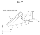
- FIG. 7A is a side view of the operation panel in an initial posture position
- FIG. 7B is a side view of the operation panel in a second posture position
- FIG. 7C is a side view of the operation panel in a third posture position
- FIG. 7D is a side view of the operation panel in a release posture position
- FIG. 8 is a perspective view of the angle adjustment device
- FIG. 9A is a top view of the angle adjustment device
- FIG. 9B is a side view of the angle adjustment device
- FIG. 9C is a front view of the angle adjustment device
- FIG. 10 is an exploded perspective view of an upper side of the angle adjustment device
- FIG. 11 is an exploded perspective view of a rear side of the angle adjustment device
- FIG. 12 is a perspective view of a shaft bracket used for a first connection portion
- FIG. 13 is a fragmentary sectional view of the first connection portion
- FIG. 14 is a perspective view of a shaft bracket used for a second connection portion
- FIG. 15 is a cross sectional view of the second connection portion
- FIG. 16 is a perspective view of a restriction bracket
- FIG. 17 is a side view showing a positional relationship among respective elements of the first connection portion
- FIG. 18A is a plan view of a lock piece
- FIG. 18B is a plan view of a side plate of a fixed bracket
- FIG. 18C is a plan view of a side plate of a movable bracket
- FIG. 19A is a plan view of the movable bracket located at the initial posture position
- FIG. 19B is a plan view of the movable bracket located at the second posture position
- FIG. 19C is a plan view of the movable bracket located at the third posture position.
- FIG. 19D is a plan view of the movable bracket located at the release posture position.
- FIG. 1 is a fragmentary sectional view of an angle adjustment device of an operation panel in an image reading system according to the first exemplary embodiment.
- the angle adjustment device of the operation panel includes a fixed portion 101 , a movable portion 102 , a connection portion 132 and an elastic member 104 .
- the fixed portion 101 is fixed on a chassis of the image reading system or the like.
- the movable portion 102 can rotate with respect to the fixed portion 101 .
- the connection portion 132 connects the fixed portion 101 and the movable portion 102 .
- the elastic member 104 is arranged between the movable portion 102 and the fixed portion 101 . A kinetic friction generated between the movable portion 102 and the fixed portion 101 restricts a rotational movement of the movable portion 102 .
- the image reading system can be provided in which an impact which is generated when a posture of the operation panel is changed is eased by restricting the rotational movement of the movable portion 102 with the kinetic friction.
- FIG. 2 is a perspective view of an angle adjustment device of an operation panel according to the second exemplary embodiment. Further, for convenience of explanation, a longitudinal direction of the operation panel is defined as an X-axis, a depth direction of the operation panel is defined as a Y-axis, and a vertical direction of the operation panel is defined as a Z-axis. In FIG. 2 , a panel surface of the operation panel is on an X-Y plane.
- a right hand side indicates a positive X(+X) direction
- a left hand side indicates a negative X( ⁇ X) direction
- a rear side indicates a positive Y(+Y) direction
- a front side indicates a negative Y( ⁇ Y) direction
- an upper side indicates a positive Z(+Z) direction
- a lower side indicates a negative Z( ⁇ Z) direction.
- the angle adjustment device of the second exemplary embodiment is used for setting a posture of an operation panel 31 provided in an image reading system such as a facsimile machine and a copy machine.
- the angle adjustment device includes a fixed portion 30 a and a movable portion 30 b .
- the operation panel 31 is provided in the movable portion 30 b .
- the movable portion 30 b is fixed on a rear side of the operation panel 31 .
- the movable portion 30 b is connected by using a connection portion 32 so as to rotate around an axis line 33 along the X-axis.
- the axis line 33 is a rotational axis of the movable portion 30 b and also is a center axis of the connection portion 32 .
- the connection portion 32 is fixed on the fixed portion 30 a .
- the connection portion 32 is provided at both ends of the movable portion 30 b in the X-axis direction.
- the operation panel 31 includes a panel portion 31 a of a touch panel type liquid crystal display (LCD) device or the like and a key portion 31 b such as an operation key or the like.
- the operation panel 31 has an operation substrate (not shown) arranged therein.
- FIG. 3 is a side view from the (+X) direction side in the angle adjustment device. As shown in FIG. 3 , the connection portion 32 located at the end of the movable portion 30 b in the (+X) direction side is covered with a connection portion cover 21 .
- the connection portion cover 21 is detachable.
- the movable portion 30 b is covered with a movable portion cover 34 .
- the movable portion cover 34 is fixed on the movable portion 30 b , and covers a rear surface of the operation panel 31 .
- a fixed portion cover 35 having approximately semi-cylindrical shape is provided to cover the fixed portion 30 a in the ( ⁇ Z) direction side.
- FIG. 4 is a side view of the operation panel in which the connection portion cover of the angle adjustment device is removed. As shown in FIG. 4 , inside of the connection portion 32 is exposed by removing the connection portion cover 21 in FIG. 3 .
- FIG. 5 is a cross sectional view showing a cross section along a line A-A in FIG. 2 . As shown in FIG. 5 , an edge 34 a of the movable portion cover 34 in the (+Y) direction side has contact with an outer surface of the fixed portion cover 35 .
- FIG. 6 is a perspective view of the angle adjustment device from the ( ⁇ Z) direction side (a rear side of the operation panel). As shown in FIG. 6 , a plurality of fixed portion cover grooves 35 a with a circular arc shape of which center is located on the axis line 33 are formed on the outer surface of the fixed portion cover 35 .
- a plurality of movable portion cover projections 34 a (refer to FIG. 5 ) which fit into a plurality of the fixed portion cover grooves 35 a are provided at the edge 34 a of the movable portion cover 34 in the (+Y) direction side.
- a method for setting the posture of the operation panel 31 will be described with reference to FIG. 7A to FIG. 7D .
- a ratchet mechanism is adopted in the connection portion 32 .
- the movable portion 30 b can be set at several postures. Further, the ratchet mechanism will be described in detail later.
- the user When the user wants to change an angle of the operation panel 31 , the user pushes up the movable portion 30 b in the (+Z) direction.
- the direction of pushing up the movable portion 30 b is described as a forward direction R 1 .
- the direction of pushing down the movable portion 30 b is described as a backward direction R 2 .
- the movable portion 30 b When the movable portion 30 b is pushed up in the forward direction R 1 , the movable portion 30 b can take three different posture positions, that are an initial posture position ( FIG. 7A ), a second posture position ( FIG. 7B ) and a third posture position ( FIG. 7C ).
- the initial posture position is the most tilted position in the ( ⁇ Z) direction of the operation panel 31 .
- the user wants to return the movable portion 30 b to the initial posture position from the third posture position again, the user rotates the movable portion 30 b in the direction R 1 and pushes up the movable portion 30 b to a release posture position ( FIG. 7D ).
- the ratchet mechanism prevents the movable portion 30 b from rotating in the backward direction R 2 when a posture of the operation panel 31 is changed.
- the posture of the operation panel 31 can be changed only by pushing up the movable portion 30 b . If the locking is released by pushing up the movable portion 30 b to the release posture position, the operation panel 31 and the movable portion 30 b return to the initial posture position by their own weight.
- the movable portion 30 b rotates in the backward direction R 2 . Because potential energy of the movable portion 30 b at the initial posture position is smaller than the potential energy at the release posture position, the movable portion 30 b returns to the initial posture position by its own weight.
- the spring is set so that a spring force acts at least in the forward direction R 1 . Accordingly, a speed at which the movable portion 30 b returns to the initial posture position is reduced and occurrence of the impact is suppressed.
- the operation panel 31 may rotate in the forward direction R 1 by the spring force, for example, when the user touches the operation panel 31 .
- the posture of the operation panel 31 is changed unnecessarily, operability of the operation panel 31 is deteriorated and commercial value of the image reading system is reduced.
- the impact which is generated when the operation panel 31 returns to the initial posture position is reduced without deteriorating the operability of the operation panel 31 .
- FIG. 8 is a perspective view showing an inside of the angle adjustment device according to the second exemplary embodiment.
- FIG. 9A is a top view from the (+Z) direction side in the angle adjustment device
- FIG. 9B is aside view from the (+X) direction side in the angle adjustment device
- FIG. 9C is a side view from the ( ⁇ Y) direction side in the angle adjustment device.
- the fixed portion 30 a includes a fixed bracket 1
- the movable portion 30 b includes a movable bracket 2
- the fixed bracket 1 and the movable bracket 2 are regarded as a rigid body.
- connection portion 32 includes a first connection portion 3 a located in the (+X) direction and a second connection portion 3 b located in the ( ⁇ X) direction that connect the fixed bracket 1 with the movable bracket 2 .
- connection portion 32 includes a pair of springs 13 .
- the springs 13 are located inside the connection portion 32 .
- One ends of these springs 13 are connected to the first connection portion 3 a and the second connection portion 3 b and the other ends are connected to the fixed bracket 1 .
- the fixed bracket 1 is provided along the X-axis, and a side plate la is provided at each of both ends of the fixed bracket 1 .
- a plate surface of the side plate la is a plane parallel to a Y-Z plane.
- the movable bracket 2 is provided along the X-axis, and a side plate 2 a is provided at each of both ends of the movable bracket 2 . Apart of the side plate 1 a overlaps a part of the side plate 2 a.
- the first connection portion 3 a and the second connection portion 3 b connect the fixed bracket 1 to the movable bracket 2 .
- a width T 1 of the fixed bracket 1 along the X-axis is narrower than a width T 2 of the movable bracket 2 . Therefore, the side plate 1 a of the fixed bracket 1 is arranged inside the side plate 2 a of the movable bracket 2 .
- FIG. 10 is an exploded perspective view showing a configuration of the side plate 1 a of the fixed bracket 1 and the side plate 2 a of the movable bracket 2 .
- the burring tap 9 is a screw hole into which shaft portion of the first connection portion 3 a or the second connection portion 3 b is screwed as mentioned below.
- the opening 8 is an opening for setting the movable portion 30 b at several positions.
- the shaft insertion hole 7 is a hole into which the shaft portion of the first connection portion 3 a or the second connection portion 3 b is inserted.
- the opening 5 is set to a position corresponding to the opening 8 .
- the fixed bracket 1 and the movable bracket 2 are connected with each other while the burring tap 9 is set to a position corresponding to the shaft insertion hole 7 .
- an elastic member 4 such as a silicon rubber or the like is arranged between the side plate 1 a of the fixed bracket 1 and the side plate 2 a of the movable bracket 2 on the first connection portion 3 a side.
- a shape of the elastic member 4 is of a washer shape and the elastic member 4 is arranged so as to have contact with plate faces of the side plate 1 a and the side plate 2 a.
- the elastic member 4 When the shape of the elastic member 4 is not of the washer shape, because distribution of the kinetic friction becomes non-isotropic with respect to the axis line 33 , the elastic member 4 is twisted and a desired braking force may not be obtained.
- the shape of the elastic member 4 is of the washer shape, the distribution of the kinetic friction becomes isotropic centering around the axis line 33 . Therefore, the elastic member 4 is not twisted, and the desired braking force can be obtained.
- connection portion 32 Next, a configuration of the connection portion 32 will be described with reference to an exploded perspective view shown in FIG. 11 .
- the first connection portion 3 a is provided in the (+X) direction side, and also the first connection portion 3 a is provided in the ( ⁇ X) direction side.
- the first connection portion 3 a to which the elastic member 4 is provided includes a lock piece 10 , a shaft bracket 11 a and a restriction bracket 12 , and these are arranged coaxially with the axis line 33 .
- the second connection portion 3 b includes the lock piece 10 , the shaft bracket 11 b and the restriction bracket 12 , and these are arranged coaxially with the axis line 33 .
- the lock piece 10 and the restriction bracket 12 of the first connection portion 3 a have the same construction as those of the second connection portion 3 b . Accordingly, the shaft bracket 11 a of the first connection portion 3 a is different from the shaft bracket 11 b of the second connection portion 3 b.
- the lock piece 10 , the shaft brackets 11 a and 11 b , and the restriction bracket 12 are arranged on an outer surface of the side plate 2 a of the movable bracket 2 in this order.
- a shaft insertion opening 10 c is provided on the lock piece 10 to configure the ratchet mechanism.
- the shaft brackets 11 a and 11 b connect the movable bracket 2 and the fixed bracket 1 and include shaft portions 14 a and 14 b extending along the axis line 33 , respectively.
- the shaft portions 14 a and 14 b are inserted through the opening 10 c of the lock piece 10 and the shaft insertion hole 7 and are screwed into the burring tap 9 , respectively.
- the lock piece 10 , the movable bracket 2 and the fixed bracket 1 are fixed by the shaft portions 14 a and 14 b.
- FIG. 12 is a perspective view of the shaft bracket 11 a .
- a fine pitch thread (not shown) screwed into the burring tap 9 is formed at a tip part of the shaft portion 14 a
- a step part 19 is formed at a base end (root part) of the shaft portion 14 a.
- a plurality of tooth parts 16 for restricting rotation of the shaft bracket 11 a are formed on an outer circumference of a plate portion 15 .
- FIG. 13 is a fragmentary sectional view of the first connection portion 3 a along a line B-B in FIG. 11 .
- FIG. 11 is an exploded perspective view
- FIG. 13 is a cross sectional view of the assembled first connection portion 3 a.
- the shaft portion 14 a is screwed into the burring tap 9 of the fixed bracket 1 .
- the step part 19 touches the outer surface of the movable bracket 2 .
- An insertion amount of the shaft portion 14 a screwed into the burring tap 9 is adjusted according to a rotation amount of the shaft bracket 11 a.
- a force with which the step part 19 pushes the movable bracket 2 can be adjusted by adjusting the insertion amount.
- the force with which the step part 19 pushes the movable bracket 2 is a fastening force for fastening the movable bracket 2 to the fixed bracket 1 .
- a compression amount of the elastic member 4 provided between the movable bracket 2 and the fixed bracket 1 varies according to the fastening force.
- the compression amount of the elastic member 4 corresponds to the kinetic friction generated by the elastic member 4 .
- the kinetic friction can be adjusted by adjusting the compression amount.
- the compression amount of the elastic member 4 can be adjusted within a range from 0.1 mm to 0.3 mm.
- the step part 19 A includes a gap K formed between the movable bracket 2 and the plate portion 15 so that the lock piece 10 can move.
- a size of the gap K is longer than the thickness of the lock piece 10 by about 0.5 mm.
- FIG. 14 is a perspective view of the shaft bracket 11 b .
- FIG. 15 is a fragmentary sectional view of the second connection portion 3 b along a line C-C in FIG. 11 .
- FIG. 11 is an exploded perspective view, and
- FIG. 15 is a cross sectional view of the assembled second connection portion 3 b.
- the shaft bracket 11 b includes a shaft portion 14 b and a plate portion 15 like the shaft bracket 11 a .
- a coarse thread (not shown) screwed into the burring tap 9 is formed at a tip part of the shaft portion 14 b
- the step part 19 is formed at a base end (root part) of the shaft portion 14 b.
- a screw pitch formed at a tip part of the shaft portion 14 a is different from that formed at a tip part of the shaft portion 14 b . Therefore, the screw pitch of the burring tap 9 in the first connection portion 3 a is also different from the screw pitch of the burring tap 9 in the second connection portion 3 b . For the following reasons, the screw pitch of the shaft portion 14 a and the shaft portion 14 b are different.
- the kinetic friction can be adjusted according to the insertion amount of the shaft portion 14 a screwed into the burring tap 9 .
- the insertion amount In order to adjust the kinetic friction with high accuracy, the insertion amount has to be set with high accuracy. Accordingly, in order to set the insertion amount with high accuracy, the screw pitch of the shaft portion 14 a is made small.
- the step part 19 includes the gap K formed between the movable bracket 2 and the plate portion 15 so that the lock piece 10 can move. Furthermore, the gap K absorbs a part tolerance of an entire width dimension T 2 (refer to FIG. 8 ) of the fixed bracket 1 and the part tolerance of an entire width dimension T 1 (refer to FIG. 8 ) of the movable bracket 2 .
- the shaft bracket 11 a is rotated by the kinetic friction.
- the shaft bracket 11 a rotates, the insertion amount of the shaft bracket 11 a screwed into the burring tap 9 varies.
- a change of the amount of screwing means a change of the braking force.
- the movable portion 30 b does not move smoothly. If the braking force becomes small, when the movable portion 30 b returns to the initial posture position, the impact generates. Accordingly, the rotational movement of the shaft brackets 11 a and 11 b is restricted by the restriction bracket 12 .
- FIG. 16 is a perspective view of the restriction bracket 12 .
- the restriction bracket 12 includes two dowels 17 , an opening 20 and an arch hole 18 .
- Two dowels 17 restrict rotation of the shaft brackets 11 a and 11 b.
- the arch hole 18 is a through hole of arch-like shape into which a screw for fixing the restriction bracket 12 on the fixed bracket 1 is inserted.
- FIG. 17 is a side view showing a positional relationship among respective elements of the first connection portion 3 a shown in FIG. 11 .
- Operations of the restriction bracket 12 of the first connection potion 3 a are the same as operations of the restriction bracket 12 of the second connection portion 3 b . Therefore, the operations of the restriction bracket 12 of the first connection portion 3 a will be described as an example.
- the tooth part 16 of the shaft bracket 11 a is provided at thirty degree intervals around the axis line 33 as a center axis.
- the two dowels 17 provided on the restriction bracket 12 engage with the tooth part 16 . Accordingly, the two dowels 17 restrict the rotation of the shaft bracket 11 a.
- a screw 18 a is inserted into the arch hole 18 of the restriction bracket 12 .
- the screw 18 a fixes the restriction bracket 12 on the fixed bracket 1 .
- the arch hole 18 of the restriction bracket 12 is located in the range of ⁇ 15 degrees around the axis line 33 from a reference position P.
- the restriction bracket 12 can be rotated within the range after loosening the screw 18 a inserted into the arch hole 18 , and the shaft bracket 11 a engaging via the dowels 17 can be rotated.
- the insertion amount of the shaft bracket 11 a screwed into the fixed bracket 1 that is, the braking force against the movable portion 30 b can be adjusted. Since the shaft bracket 11 a is fixed by fastening the screw 18 a , the adjusted braking force does not varies.
- connection portion cover 21 By removing the connection portion cover 21 shown in FIG. 3 , the restriction bracket 12 is exposed outside (refer to FIG. 4 ). Accordingly, the braking force can be easily adjusted by removing the connection portion cover 21 .
- the ratchet mechanism includes the side plate 2 a of the movable bracket 2 , the side plate 1 a of the fixed bracket 1 , the lock piece 10 , the opening 5 of the side plate 2 a , the opening 8 of the side plate 1 a , the shaft portion 14 a and the spring 13 .
- the ratchet mechanism of the first connection portion 3 a has the same construction as that of the second connection portion 3 b , only the first connection portion 3 a is exemplified.
- FIG. 18A is a plan view of the lock piece 10 .
- the lock piece 10 includes a claw portion 10 b , the opening 10 c and a plate portion 10 a . As shown in FIG. 10 and FIG. 11 , the claw portion 10 b is inserted into the opening 5 of the movable bracket 2 and the opening 8 of the fixed bracket 1 .
- the opening 10 c is an elongate hole provided in the plate portion 10 a . Since a major axis (Y-axis) of the opening 10 c is formed so as to be larger than a diameter of the shaft portion 14 a , a space S is formed in the direction of the major axis. Accordingly, the shaft portion 14 a can move the distance of the space S in the Y-axis direction.
- the claw portion 10 b of the lock piece 10 is formed by bending an edge portion of the ( ⁇ Y) direction of the lock piece 10 for the ( ⁇ X) direction.
- One end of the spring 13 is connected to the claw portion 10 b .
- the other end of the spring 13 is connected to the fixed bracket 1 . This spring 13 always pulls the lock piece 10 to the forward direction R 1 .
- FIG. 18B is an expanded plan view of the side plate la of the fixed bracket 1 .
- the opening 8 of the fixed bracket 1 is provided in the side plate 1 a , and a shape of the opening 8 is approximately L shape.
- the opening 8 includes a first contact portion 8 a and a second contact portion 8 b.
- a distance between the second contact portion 8 b and the axis line 33 is larger than the distance between the first contact portion 8 a and the axis line 33 .
- FIG. 18C is an expanded plan view of the side plate 2 a of the movable bracket 2 .
- the opening 5 is provided in the side plate 2 a .
- a plurality of lock portions 5 aa , 5 ab and 5 ac to which the claw portion 10 b of the lock piece 10 contacts are formed in the opening 5 .
- the opening 5 includes an edge 5 b to the forward direction R 1 , and includes an edge 5 c to the backward direction R 2 .
- FIG. 19A is an enlarged plan view from the (+X) direction side showing a positional relationship among the lock piece 10 , the side plate 1 a of the fixed bracket 1 and the side plate 2 a of the movable bracket 2 when the movable bracket 2 is located at the initial posture position ( FIG. 7A ).
- the claw portion 10 b of the lock piece 10 touches the edge 5 b of the opening 5 and touches the first contact portion 8 a of the opening 8 .
- the movable bracket 2 when the movable bracket 2 is in the initial posture position, the movable bracket 2 can be rotated only in the forward direction R 1 .
- FIG. 19B is an enlarged plan view showing the movable bracket 2 which is located at the second posture position ( FIG. 7B ).
- the lock portion 5 aa of the side plate 2 a touches the claw portion 10 b.
- the side plate 2 a cannot rotate in the backward direction R 2 from the second posture position.
- FIG. 19C is an enlarged plan view showing the movable bracket 2 which is located at the third posture position ( FIG. 7C ). If the movable bracket 2 is located at the third posture position, the lock portion 5 ab of the side plate 2 a touches the claw portion 10 b.
- the side plate 2 a cannot rotate in the backward direction R 2 from the third posture position.
- FIG. 19D is an enlarged plan view showing the movable bracket 2 which is located at the release posture position ( FIG. 7D ).
- the edge 5 c of the opening 5 touches the claw portion 10 b.
- the claw portion 10 b climbs over the first contact portion 8 a and moves in the ( ⁇ Y) direction side, and the claw portion 10 b touches the second contact portion 8 b . If touching the second contact portion 8 b , the claw portion 10 b moves away from the axis line 33 in the space S.
- the lock state is released, because the lock portion 5 a does not touch the claw portion 10 b , when the movable bracket 2 moves in the backward direction R 2 .
- the movable bracket 2 can return to the initial posture position due to a restoring force of the spring 13 .
- the elastic member 4 generates the kinetic friction when the movable bracket 2 rotates. Because the kinetic friction acts as the braking force when the movable bracket 2 returns from the release posture position to the initial posture position, the movable bracket 2 returns to the initial posture position at the slow speed.
- the braking force can be adjusted by adjusting the insertion amount of the shaft bracket.
- the elastic member is made of an abrasion resistance material such as silicon rubber or the like.
- an abrasion resistance material such as silicon rubber or the like.
- the braking force has to be readjusted.
- readjustment of the braking force can be easily performed because the shaft bracket is exposed only by removing the connection portion cover.
- the fixed bracket is integrally formed and the movable bracket is also integrally formed.
- at least one of the fixed bracket and the movable bracket can be formed by using a plurality of parts.
- the elastic member is provided in the first connection portion.
- the elastic member can be provided in the second connection portion.
- the elastic member can be provided in both the first connection portion and the second connection portion side.
- the elastic member is provided in both the first connection portion and the second connection portion, it is advantageous that twist of the operation panel is unlikely to occur.
- Each member used for the exemplary embodiment can be a metal plate or made of a molding material of resin.
- the angle adjustment device used for adjusting an angle of the operation panel is described as an example.
- the invention can be applied to the operation panel as well as to a general mechanism which receives a downward force and needs a force to be moved upward.
- An angle adjustment device includes a fixed bracket, a movable bracket having a side panel corresponding to a side panel of the fixed bracket, a connection portion which connects the fixed bracket to the movable bracket so as to rotate around the axis line perpendicular to the side plate of the movable bracket and an elastic member arranged between the side plate of the fixed bracket and the side plate of the movable bracket.
- the elastic member touches the side plate of the fixed bracket and the side plate of the movable bracket to generate a kinetic friction when the movable bracket rotates.
Landscapes
- Engineering & Computer Science (AREA)
- Multimedia (AREA)
- Signal Processing (AREA)
- Facsimiles In General (AREA)
- Pivots And Pivotal Connections (AREA)
Abstract
Description
Claims (4)
Priority Applications (1)
| Application Number | Priority Date | Filing Date | Title |
|---|---|---|---|
| US13/444,331 US8727292B2 (en) | 2008-04-09 | 2012-04-11 | Image reading system using an angle adjustment device |
Applications Claiming Priority (4)
| Application Number | Priority Date | Filing Date | Title |
|---|---|---|---|
| JP2008101853A JP4530296B2 (en) | 2008-04-09 | 2008-04-09 | Variable angle structure |
| JP2008-101853 | 2008-04-09 | ||
| US12/408,269 US20090257818A1 (en) | 2008-04-09 | 2009-03-20 | Angle adjustment device and image reading system using the same |
| US13/444,331 US8727292B2 (en) | 2008-04-09 | 2012-04-11 | Image reading system using an angle adjustment device |
Related Parent Applications (1)
| Application Number | Title | Priority Date | Filing Date |
|---|---|---|---|
| US12/408,269 Division US20090257818A1 (en) | 2008-04-09 | 2009-03-20 | Angle adjustment device and image reading system using the same |
Publications (2)
| Publication Number | Publication Date |
|---|---|
| US20120193495A1 US20120193495A1 (en) | 2012-08-02 |
| US8727292B2 true US8727292B2 (en) | 2014-05-20 |
Family
ID=41164118
Family Applications (2)
| Application Number | Title | Priority Date | Filing Date |
|---|---|---|---|
| US12/408,269 Abandoned US20090257818A1 (en) | 2008-04-09 | 2009-03-20 | Angle adjustment device and image reading system using the same |
| US13/444,331 Expired - Fee Related US8727292B2 (en) | 2008-04-09 | 2012-04-11 | Image reading system using an angle adjustment device |
Family Applications Before (1)
| Application Number | Title | Priority Date | Filing Date |
|---|---|---|---|
| US12/408,269 Abandoned US20090257818A1 (en) | 2008-04-09 | 2009-03-20 | Angle adjustment device and image reading system using the same |
Country Status (3)
| Country | Link |
|---|---|
| US (2) | US20090257818A1 (en) |
| JP (1) | JP4530296B2 (en) |
| CN (1) | CN101557449B (en) |
Families Citing this family (8)
| Publication number | Priority date | Publication date | Assignee | Title |
|---|---|---|---|---|
| JP5821533B2 (en) * | 2011-10-31 | 2015-11-24 | ブラザー工業株式会社 | Operation panel unit and image forming apparatus |
| US10323682B2 (en) * | 2015-07-25 | 2019-06-18 | Kolberg-Pioneer, Inc. | Apparatus and method for an actuator mounting assembly with a rocker pin |
| US10285496B2 (en) * | 2016-06-03 | 2019-05-14 | Designa Inc. | Height adjustment mechanism and platform |
| CN105901923B (en) | 2016-06-03 | 2017-10-24 | 佛山市迪赛纳科技有限公司 | Elevating mechanism and self-powered platform and worktable lifting method comprising elevating mechanism |
| USD841369S1 (en) | 2016-08-01 | 2019-02-26 | Designa Inc. | Height adjustment platform |
| RU2641433C9 (en) * | 2016-11-25 | 2020-04-06 | Общество с ограниченной ответственностью "СТРОЙИННОВАЦИЯ" | Fastening bracket |
| USD843137S1 (en) | 2017-08-21 | 2019-03-19 | Designa Inc. | Height adjustable workstation |
| CN111941115A (en) * | 2020-08-18 | 2020-11-17 | 徐州工业职业技术学院 | Clamp for machining inclined hole on workpiece |
Citations (41)
| Publication number | Priority date | Publication date | Assignee | Title |
|---|---|---|---|---|
| US213775A (en) | 1879-04-01 | Improvement in adjustable brackets | ||
| US702304A (en) | 1902-03-03 | 1902-06-10 | Edwin M Hulse | Hinge. |
| US1836053A (en) * | 1931-02-26 | 1931-12-15 | John E Sjostrom Company | Adjustable drawing board |
| US2030348A (en) * | 1935-05-27 | 1936-02-11 | American Seating Co | Desk |
| JPS5181188A (en) | 1975-01-10 | 1976-07-15 | Hitachi Ltd | |
| JPS58181876A (en) | 1982-01-21 | 1983-10-24 | オロンジオ・ド・ノラ・ソシエテ・アノニム | Anode |
| US4421035A (en) * | 1980-04-15 | 1983-12-20 | Triumph-Adler A.G. Fur Buro-Und Informationstechnik | Apparatus for locking a keyboard at selected inclinations to a horizontal reference |
| JPS6052412A (en) | 1983-08-11 | 1985-03-25 | コサン クリスプラント アクチ−セルスカブ | Leading-in conveyor |
| JPS6377122A (en) | 1986-09-19 | 1988-04-07 | Matsushita Electric Ind Co Ltd | Manufacture of semiconductor device |
| US4934645A (en) | 1989-03-20 | 1990-06-19 | Rtc Industries, Inc. | Shelving assembly |
| JPH0351475A (en) | 1989-07-17 | 1991-03-05 | Sanwa Kako Kk | Manufacture of corner member of building plate |
| JPH03106739A (en) | 1989-09-21 | 1991-05-07 | Koufu Nippon Denki Kk | Sheet carrying device |
| US5109572A (en) | 1989-09-23 | 1992-05-05 | Hyundai Electronics Ind. Co., Ltd. | Locking hinge device for the LCD screen of a word processor |
| US5228873A (en) * | 1992-02-28 | 1993-07-20 | Honda Tsushin Kogyo Kabushiki Kaisha | Metallic-shell-equipped electrical connector |
| US5292097A (en) | 1989-10-31 | 1994-03-08 | Russell Edwin R | Work surface support |
| JPH07319396A (en) | 1994-05-30 | 1995-12-08 | Nec Eng Ltd | Tilting mechanism |
| US5765794A (en) | 1996-09-12 | 1998-06-16 | Chen; Ping | Angle adjusting device for an instrument panel |
| US6116557A (en) * | 1998-07-10 | 2000-09-12 | Acco Brands, Inc. | Keyboard support system |
| JP3106739B2 (en) | 1992-11-19 | 2000-11-06 | 株式会社豊田自動織機製作所 | Scroll compressor |
| JP2001146874A (en) | 1999-11-22 | 2001-05-29 | Nec Shizuoka Ltd | Tilt structure for oa equipment, and liquid crystal monitor using it |
| US6296217B1 (en) | 1998-09-29 | 2001-10-02 | Pioneer Corporation | Movable body supporting mechanism |
| US6354549B2 (en) * | 1999-11-02 | 2002-03-12 | Ergotron, Inc. | Ratcheted pivot |
| US6353968B1 (en) * | 1999-09-14 | 2002-03-12 | Acer Peripherals, Inc. | Single-button support mechanism |
| US6354552B1 (en) * | 1999-03-18 | 2002-03-12 | Posiflex Business Machines, Inc. | Tilt angle adjustable stand for LCD display |
| US6378830B1 (en) * | 2000-10-05 | 2002-04-30 | Lu Sheng-Nan | Adjustable support for an LCD monitor |
| US20030001057A1 (en) * | 1996-06-07 | 2003-01-02 | Ergotron, Inc. | Pivot assembly and support system |
| US6502792B1 (en) * | 1999-10-26 | 2003-01-07 | Samsung Electronics Co., Ltd. | LCD monitor stand having a multistage structure |
| JP2003259048A (en) | 2002-02-27 | 2003-09-12 | Panasonic Communications Co Ltd | Supporting device of display panel body, and communication device using the device |
| CN1610496A (en) | 2003-10-17 | 2005-04-27 | 三星电子株式会社 | Display apparatus |
| US20050103960A1 (en) | 2003-11-18 | 2005-05-19 | 3M Innovative Properties Company | Adjustable keyboard support assembly method of use |
| US20050205735A1 (en) * | 2004-02-13 | 2005-09-22 | Fujitsu Limited | Display tilting apparatus |
| US20060145038A1 (en) | 2005-01-04 | 2006-07-06 | Benq Corporation | Hanger for electronic apparatus |
| US20060273228A1 (en) | 2005-06-06 | 2006-12-07 | Knape & Vogt Manufacturing Company | Adjustable support assembly |
| US7261267B2 (en) * | 2003-02-03 | 2007-08-28 | Bang & Olufsen A/S | Tilt mechanism |
| US7261272B2 (en) * | 2005-05-18 | 2007-08-28 | Lang Mekra North America, Llc | Conical support arm joint for a vehicle mirror |
| JP2007334157A (en) | 2006-06-16 | 2007-12-27 | Murata Mach Ltd | Image forming apparatus |
| US7335119B2 (en) | 2005-09-29 | 2008-02-26 | Russell Corporation | Ratchet elevator system |
| US7417695B2 (en) * | 2005-08-08 | 2008-08-26 | Posiflex Inc. | Mechanism for adjusting an elevation angle of an LCD |
| US7679892B2 (en) * | 2007-08-01 | 2010-03-16 | Samsung Electronics Co., Ltd. | Supporting device for display apparatus and display apparatus having the same |
| US7690081B2 (en) * | 2006-12-21 | 2010-04-06 | Jr-Jiun Chern | Hinge for laptop computer |
| US7694922B2 (en) | 2006-08-10 | 2010-04-13 | Samsung Electronics Co., Ltd. | Supporting apparatus for display devices and display device having the same |
Family Cites Families (12)
| Publication number | Priority date | Publication date | Assignee | Title |
|---|---|---|---|---|
| JPS438854Y1 (en) * | 1964-02-05 | 1968-04-18 | ||
| JPS434883Y1 (en) * | 1964-08-27 | 1968-03-02 | ||
| JPS5181188U (en) * | 1974-12-20 | 1976-06-28 | ||
| JPS58181876U (en) * | 1982-05-31 | 1983-12-05 | 株式会社エ−ワ | Hinge device for art cases |
| JPS6052412U (en) * | 1983-09-20 | 1985-04-12 | 株式会社ヨコオ | refraction mechanism |
| JPH0443589Y2 (en) * | 1986-11-07 | 1992-10-14 | ||
| JPH0638449Y2 (en) * | 1988-02-08 | 1994-10-05 | 富士通株式会社 | Cover structure |
| JPH03106739U (en) * | 1990-02-17 | 1991-11-05 | ||
| US6809713B2 (en) * | 2002-02-27 | 2004-10-26 | Ching-Lung Peng | Aluminum-extruded LCD frame |
| KR100463524B1 (en) * | 2002-05-29 | 2004-12-29 | 엘지전자 주식회사 | Hinge assembly for video display appliance |
| CN2630983Y (en) * | 2003-07-29 | 2004-08-04 | 王鼎 | Inclined-block precise driving mechanism for bar code analytic image electronic display screen |
| JP3106739U (en) * | 2004-07-22 | 2005-01-20 | 呈杰股▲ふん▼有限公司 | Axial device with elevation mounting part |
-
2008
- 2008-04-09 JP JP2008101853A patent/JP4530296B2/en not_active Expired - Fee Related
-
2009
- 2009-03-20 US US12/408,269 patent/US20090257818A1/en not_active Abandoned
- 2009-04-09 CN CN2009101341731A patent/CN101557449B/en not_active Expired - Fee Related
-
2012
- 2012-04-11 US US13/444,331 patent/US8727292B2/en not_active Expired - Fee Related
Patent Citations (43)
| Publication number | Priority date | Publication date | Assignee | Title |
|---|---|---|---|---|
| US213775A (en) | 1879-04-01 | Improvement in adjustable brackets | ||
| US702304A (en) | 1902-03-03 | 1902-06-10 | Edwin M Hulse | Hinge. |
| US1836053A (en) * | 1931-02-26 | 1931-12-15 | John E Sjostrom Company | Adjustable drawing board |
| US2030348A (en) * | 1935-05-27 | 1936-02-11 | American Seating Co | Desk |
| JPS5181188A (en) | 1975-01-10 | 1976-07-15 | Hitachi Ltd | |
| US4421035A (en) * | 1980-04-15 | 1983-12-20 | Triumph-Adler A.G. Fur Buro-Und Informationstechnik | Apparatus for locking a keyboard at selected inclinations to a horizontal reference |
| JPS58181876A (en) | 1982-01-21 | 1983-10-24 | オロンジオ・ド・ノラ・ソシエテ・アノニム | Anode |
| JPS6052412A (en) | 1983-08-11 | 1985-03-25 | コサン クリスプラント アクチ−セルスカブ | Leading-in conveyor |
| JPS6377122A (en) | 1986-09-19 | 1988-04-07 | Matsushita Electric Ind Co Ltd | Manufacture of semiconductor device |
| US4934645A (en) | 1989-03-20 | 1990-06-19 | Rtc Industries, Inc. | Shelving assembly |
| JPH0351475A (en) | 1989-07-17 | 1991-03-05 | Sanwa Kako Kk | Manufacture of corner member of building plate |
| JPH03106739A (en) | 1989-09-21 | 1991-05-07 | Koufu Nippon Denki Kk | Sheet carrying device |
| US5109572A (en) | 1989-09-23 | 1992-05-05 | Hyundai Electronics Ind. Co., Ltd. | Locking hinge device for the LCD screen of a word processor |
| US5292097A (en) | 1989-10-31 | 1994-03-08 | Russell Edwin R | Work surface support |
| US5228873A (en) * | 1992-02-28 | 1993-07-20 | Honda Tsushin Kogyo Kabushiki Kaisha | Metallic-shell-equipped electrical connector |
| JP3106739B2 (en) | 1992-11-19 | 2000-11-06 | 株式会社豊田自動織機製作所 | Scroll compressor |
| JPH07319396A (en) | 1994-05-30 | 1995-12-08 | Nec Eng Ltd | Tilting mechanism |
| US20030001057A1 (en) * | 1996-06-07 | 2003-01-02 | Ergotron, Inc. | Pivot assembly and support system |
| US5765794A (en) | 1996-09-12 | 1998-06-16 | Chen; Ping | Angle adjusting device for an instrument panel |
| US6116557A (en) * | 1998-07-10 | 2000-09-12 | Acco Brands, Inc. | Keyboard support system |
| US6296217B1 (en) | 1998-09-29 | 2001-10-02 | Pioneer Corporation | Movable body supporting mechanism |
| US6354552B1 (en) * | 1999-03-18 | 2002-03-12 | Posiflex Business Machines, Inc. | Tilt angle adjustable stand for LCD display |
| US6353968B1 (en) * | 1999-09-14 | 2002-03-12 | Acer Peripherals, Inc. | Single-button support mechanism |
| US6502792B1 (en) * | 1999-10-26 | 2003-01-07 | Samsung Electronics Co., Ltd. | LCD monitor stand having a multistage structure |
| US6354549B2 (en) * | 1999-11-02 | 2002-03-12 | Ergotron, Inc. | Ratcheted pivot |
| JP2001146874A (en) | 1999-11-22 | 2001-05-29 | Nec Shizuoka Ltd | Tilt structure for oa equipment, and liquid crystal monitor using it |
| US6378830B1 (en) * | 2000-10-05 | 2002-04-30 | Lu Sheng-Nan | Adjustable support for an LCD monitor |
| JP2003259048A (en) | 2002-02-27 | 2003-09-12 | Panasonic Communications Co Ltd | Supporting device of display panel body, and communication device using the device |
| US7261267B2 (en) * | 2003-02-03 | 2007-08-28 | Bang & Olufsen A/S | Tilt mechanism |
| CN1610496A (en) | 2003-10-17 | 2005-04-27 | 三星电子株式会社 | Display apparatus |
| US7267312B2 (en) | 2003-10-17 | 2007-09-11 | Samsung Electronics Co., Ltd. | Display apparatus |
| US20050103960A1 (en) | 2003-11-18 | 2005-05-19 | 3M Innovative Properties Company | Adjustable keyboard support assembly method of use |
| US20050205735A1 (en) * | 2004-02-13 | 2005-09-22 | Fujitsu Limited | Display tilting apparatus |
| US20060145038A1 (en) | 2005-01-04 | 2006-07-06 | Benq Corporation | Hanger for electronic apparatus |
| US7523907B2 (en) * | 2005-01-04 | 2009-04-28 | Benq Corporation | Hanger for electronic apparatus |
| US7261272B2 (en) * | 2005-05-18 | 2007-08-28 | Lang Mekra North America, Llc | Conical support arm joint for a vehicle mirror |
| US20060273228A1 (en) | 2005-06-06 | 2006-12-07 | Knape & Vogt Manufacturing Company | Adjustable support assembly |
| US7417695B2 (en) * | 2005-08-08 | 2008-08-26 | Posiflex Inc. | Mechanism for adjusting an elevation angle of an LCD |
| US7335119B2 (en) | 2005-09-29 | 2008-02-26 | Russell Corporation | Ratchet elevator system |
| JP2007334157A (en) | 2006-06-16 | 2007-12-27 | Murata Mach Ltd | Image forming apparatus |
| US7694922B2 (en) | 2006-08-10 | 2010-04-13 | Samsung Electronics Co., Ltd. | Supporting apparatus for display devices and display device having the same |
| US7690081B2 (en) * | 2006-12-21 | 2010-04-06 | Jr-Jiun Chern | Hinge for laptop computer |
| US7679892B2 (en) * | 2007-08-01 | 2010-03-16 | Samsung Electronics Co., Ltd. | Supporting device for display apparatus and display apparatus having the same |
Non-Patent Citations (5)
| Title |
|---|
| Chinese Office Action dated Nov. 5, 2012 in corresponding Chinese Patent Application No. 200910134173.1 with English translation of Chinese Office Action. |
| First Office Action issued on Sep. 23, 2011 by State Intellectual Property Office, P.R. China with English Translation, 13 pages. |
| Japanese Patent Office issued a Japanese Office Action dated Feb. 24, 2010, Application No. 2008-101853. |
| uhmwpe technical data, http://web.archive.org/web/20040414051832/http://k-mac-plastics.net/date%020sheets/uhmwpe-typical-properties.htm, Apr. 14, 2004. * |
| uhmwpe technical data, http://web.archive.org/web/20040414051832/http://k-mac-plastics.net/date%020sheets/uhmwpe—typical—properties.htm, Apr. 14, 2004. * |
Also Published As
| Publication number | Publication date |
|---|---|
| US20090257818A1 (en) | 2009-10-15 |
| US20120193495A1 (en) | 2012-08-02 |
| JP4530296B2 (en) | 2010-08-25 |
| CN101557449B (en) | 2013-10-30 |
| JP2009253851A (en) | 2009-10-29 |
| CN101557449A (en) | 2009-10-14 |
Similar Documents
| Publication | Publication Date | Title |
|---|---|---|
| US8727292B2 (en) | Image reading system using an angle adjustment device | |
| JP5014245B2 (en) | Support device with tilt mechanism | |
| JP3859009B2 (en) | LCD TV stand and display stand | |
| US20080062444A1 (en) | Angle adjustment device and image forming apparatus | |
| US20180081405A1 (en) | Hinge, stand device, and electronic apparatus | |
| US20140007379A1 (en) | Hinge and an Electronic Device Incorporating the Same | |
| CN110418737A (en) | The mounting structure with dropping mechanism of car-mounted device | |
| US20080109993A1 (en) | Hinge module for an electronic device and electronic device having the same | |
| KR102273674B1 (en) | Display Mirror Toggle Paddle | |
| TWI727805B (en) | Notebook computer | |
| CN103377589A (en) | Display capable of limiting pivoting function | |
| US7937012B2 (en) | Angle adjusting device and image forming apparatus | |
| JP5313060B2 (en) | Hinge | |
| TWI448160B (en) | Logo unit and casing thereof | |
| JP4768291B2 (en) | Angle adjusting device and image forming apparatus | |
| US6729662B2 (en) | Lockable bezel | |
| JP6663025B2 (en) | Locking of toggle switch for full screen display mirror (FDM) and toggle switch with cushioning material | |
| EP1696169B1 (en) | Adjustable support frame for a display screen | |
| US20060230689A1 (en) | Position adjustable control panel for image forming device | |
| US10596968B2 (en) | Prism toggle spring | |
| KR20120041607A (en) | Display apparatus | |
| JP4379456B2 (en) | Display screen support mechanism | |
| JP2019054475A (en) | Terminal device | |
| JP4582780B2 (en) | Angle adjusting device and image forming apparatus | |
| US11971742B2 (en) | Display assembly |
Legal Events
| Date | Code | Title | Description |
|---|---|---|---|
| AS | Assignment |
Owner name: NEC ENGINEERING LTD., JAPAN Free format text: ASSIGNMENT OF ASSIGNORS INTEREST;ASSIGNORS:SUGIYAMA, NAMIE;HATOMI, KEISUKE;REEL/FRAME:028028/0683 Effective date: 20090306 Owner name: NEC ACCESS TECHNICA, LTD, JAPAN Free format text: ASSIGNMENT OF ASSIGNORS INTEREST;ASSIGNORS:SUGIYAMA, NAMIE;HATOMI, KEISUKE;REEL/FRAME:028028/0683 Effective date: 20090306 |
|
| AS | Assignment |
Owner name: NEC PLATFORMS, LTD., JAPAN Free format text: MERGER AND CHANGE OF NAME;ASSIGNORS:NEC ACCESSTECHNICA, LTD.;NEC INFRONTIA CORPORATION;REEL/FRAME:034906/0402 Effective date: 20140701 |
|
| AS | Assignment |
Owner name: NEC PLATFORMS, LTD., JAPAN Free format text: MERGER;ASSIGNOR:NEC ENGINEERING, LTD.;REEL/FRAME:043590/0213 Effective date: 20170401 |
|
| FEPP | Fee payment procedure |
Free format text: MAINTENANCE FEE REMINDER MAILED (ORIGINAL EVENT CODE: REM.) |
|
| LAPS | Lapse for failure to pay maintenance fees |
Free format text: PATENT EXPIRED FOR FAILURE TO PAY MAINTENANCE FEES (ORIGINAL EVENT CODE: EXP.) |
|
| STCH | Information on status: patent discontinuation |
Free format text: PATENT EXPIRED DUE TO NONPAYMENT OF MAINTENANCE FEES UNDER 37 CFR 1.362 |
|
| FP | Lapsed due to failure to pay maintenance fee |
Effective date: 20180520 |