US8723522B2 - Superconductor RF coil array - Google Patents
Superconductor RF coil array Download PDFInfo
- Publication number
- US8723522B2 US8723522B2 US12/887,474 US88747410A US8723522B2 US 8723522 B2 US8723522 B2 US 8723522B2 US 88747410 A US88747410 A US 88747410A US 8723522 B2 US8723522 B2 US 8723522B2
- Authority
- US
- United States
- Prior art keywords
- superconducting
- coil
- thermally conductive
- coil array
- array according
- Prior art date
- Legal status (The legal status is an assumption and is not a legal conclusion. Google has not performed a legal analysis and makes no representation as to the accuracy of the status listed.)
- Active, expires
Links
- 239000002887 superconductor Substances 0.000 title claims description 19
- 239000000463 material Substances 0.000 claims abstract description 11
- 238000004458 analytical method Methods 0.000 claims abstract description 4
- 239000000758 substrate Substances 0.000 claims description 53
- 238000003384 imaging method Methods 0.000 claims description 28
- PNEYBMLMFCGWSK-UHFFFAOYSA-N aluminium oxide Inorganic materials [O-2].[O-2].[O-2].[Al+3].[Al+3] PNEYBMLMFCGWSK-UHFFFAOYSA-N 0.000 claims description 24
- 229910052594 sapphire Inorganic materials 0.000 claims description 12
- 239000010980 sapphire Substances 0.000 claims description 12
- 239000010409 thin film Substances 0.000 claims description 11
- 125000006850 spacer group Chemical group 0.000 claims description 3
- 238000000926 separation method Methods 0.000 claims description 2
- 238000002595 magnetic resonance imaging Methods 0.000 description 31
- 238000000034 method Methods 0.000 description 9
- 239000000523 sample Substances 0.000 description 9
- 238000013461 design Methods 0.000 description 8
- 230000008901 benefit Effects 0.000 description 7
- 210000000481 breast Anatomy 0.000 description 7
- 238000003491 array Methods 0.000 description 6
- 238000001816 cooling Methods 0.000 description 6
- 230000003595 spectral effect Effects 0.000 description 5
- 238000004804 winding Methods 0.000 description 5
- 238000010276 construction Methods 0.000 description 4
- 238000004611 spectroscopical analysis Methods 0.000 description 4
- RYGMFSIKBFXOCR-UHFFFAOYSA-N Copper Chemical compound [Cu] RYGMFSIKBFXOCR-UHFFFAOYSA-N 0.000 description 3
- 239000004593 Epoxy Substances 0.000 description 3
- 238000000701 chemical imaging Methods 0.000 description 3
- 239000010949 copper Substances 0.000 description 3
- 229910052802 copper Inorganic materials 0.000 description 3
- 230000008878 coupling Effects 0.000 description 3
- 238000010168 coupling process Methods 0.000 description 3
- 238000005859 coupling reaction Methods 0.000 description 3
- 238000009792 diffusion process Methods 0.000 description 3
- 238000005516 engineering process Methods 0.000 description 3
- 239000004519 grease Substances 0.000 description 3
- 239000007788 liquid Substances 0.000 description 3
- 230000008569 process Effects 0.000 description 3
- IJGRMHOSHXDMSA-UHFFFAOYSA-N Atomic nitrogen Chemical compound N#N IJGRMHOSHXDMSA-UHFFFAOYSA-N 0.000 description 2
- 229910001275 Niobium-titanium Inorganic materials 0.000 description 2
- 230000017531 blood circulation Effects 0.000 description 2
- 239000000919 ceramic Substances 0.000 description 2
- 238000002598 diffusion tensor imaging Methods 0.000 description 2
- 239000003814 drug Substances 0.000 description 2
- 238000002599 functional magnetic resonance imaging Methods 0.000 description 2
- 230000014509 gene expression Effects 0.000 description 2
- 239000001307 helium Substances 0.000 description 2
- 229910052734 helium Inorganic materials 0.000 description 2
- SWQJXJOGLNCZEY-UHFFFAOYSA-N helium atom Chemical compound [He] SWQJXJOGLNCZEY-UHFFFAOYSA-N 0.000 description 2
- 239000001257 hydrogen Substances 0.000 description 2
- 229910052739 hydrogen Inorganic materials 0.000 description 2
- 230000004807 localization Effects 0.000 description 2
- 230000005415 magnetization Effects 0.000 description 2
- 230000004060 metabolic process Effects 0.000 description 2
- 238000012986 modification Methods 0.000 description 2
- 230000004048 modification Effects 0.000 description 2
- RJSRQTFBFAJJIL-UHFFFAOYSA-N niobium titanium Chemical compound [Ti].[Nb] RJSRQTFBFAJJIL-UHFFFAOYSA-N 0.000 description 2
- 239000000615 nonconductor Substances 0.000 description 2
- 238000001208 nuclear magnetic resonance pulse sequence Methods 0.000 description 2
- 238000005476 soldering Methods 0.000 description 2
- 230000002123 temporal effect Effects 0.000 description 2
- UFHFLCQGNIYNRP-UHFFFAOYSA-N Hydrogen Chemical compound [H][H] UFHFLCQGNIYNRP-UHFFFAOYSA-N 0.000 description 1
- DGAQECJNVWCQMB-PUAWFVPOSA-M Ilexoside XXIX Chemical compound C[C@@H]1CC[C@@]2(CC[C@@]3(C(=CC[C@H]4[C@]3(CC[C@@H]5[C@@]4(CC[C@@H](C5(C)C)OS(=O)(=O)[O-])C)C)[C@@H]2[C@]1(C)O)C)C(=O)O[C@H]6[C@@H]([C@H]([C@@H]([C@H](O6)CO)O)O)O.[Na+] DGAQECJNVWCQMB-PUAWFVPOSA-M 0.000 description 1
- 238000012307 MRI technique Methods 0.000 description 1
- 238000005481 NMR spectroscopy Methods 0.000 description 1
- 230000006978 adaptation Effects 0.000 description 1
- 238000007792 addition Methods 0.000 description 1
- 210000003484 anatomy Anatomy 0.000 description 1
- 125000004429 atom Chemical group 0.000 description 1
- 230000005540 biological transmission Effects 0.000 description 1
- 230000000747 cardiac effect Effects 0.000 description 1
- 150000001875 compounds Chemical class 0.000 description 1
- 230000003247 decreasing effect Effects 0.000 description 1
- 238000002597 diffusion-weighted imaging Methods 0.000 description 1
- 230000003467 diminishing effect Effects 0.000 description 1
- 229940079593 drug Drugs 0.000 description 1
- 230000000694 effects Effects 0.000 description 1
- 210000003414 extremity Anatomy 0.000 description 1
- 230000005714 functional activity Effects 0.000 description 1
- 239000011521 glass Substances 0.000 description 1
- 230000036541 health Effects 0.000 description 1
- 125000004435 hydrogen atom Chemical class [H]* 0.000 description 1
- 230000003116 impacting effect Effects 0.000 description 1
- 230000008676 import Effects 0.000 description 1
- 238000001727 in vivo Methods 0.000 description 1
- 238000002955 isolation Methods 0.000 description 1
- 229910052746 lanthanum Inorganic materials 0.000 description 1
- -1 lanthanum aluminate Chemical class 0.000 description 1
- 238000012423 maintenance Methods 0.000 description 1
- 238000004519 manufacturing process Methods 0.000 description 1
- 239000002207 metabolite Substances 0.000 description 1
- 238000000386 microscopy Methods 0.000 description 1
- 229910000657 niobium-tin Inorganic materials 0.000 description 1
- 229910052757 nitrogen Inorganic materials 0.000 description 1
- 230000007170 pathology Effects 0.000 description 1
- 239000004033 plastic Substances 0.000 description 1
- 239000002985 plastic film Substances 0.000 description 1
- 238000012545 processing Methods 0.000 description 1
- 238000011160 research Methods 0.000 description 1
- 230000029058 respiratory gaseous exchange Effects 0.000 description 1
- 230000035945 sensitivity Effects 0.000 description 1
- 238000004088 simulation Methods 0.000 description 1
- 229910052708 sodium Inorganic materials 0.000 description 1
- 239000011734 sodium Substances 0.000 description 1
- 230000003068 static effect Effects 0.000 description 1
- 210000000689 upper leg Anatomy 0.000 description 1
- 229910021521 yttrium barium copper oxide Inorganic materials 0.000 description 1
Images


Classifications
-
- G—PHYSICS
- G01—MEASURING; TESTING
- G01R—MEASURING ELECTRIC VARIABLES; MEASURING MAGNETIC VARIABLES
- G01R33/00—Arrangements or instruments for measuring magnetic variables
- G01R33/20—Arrangements or instruments for measuring magnetic variables involving magnetic resonance
- G01R33/28—Details of apparatus provided for in groups G01R33/44 - G01R33/64
- G01R33/32—Excitation or detection systems, e.g. using radio frequency signals
- G01R33/34—Constructional details, e.g. resonators, specially adapted to MR
- G01R33/34015—Temperature-controlled RF coils
- G01R33/34023—Superconducting RF coils
-
- G—PHYSICS
- G01—MEASURING; TESTING
- G01R—MEASURING ELECTRIC VARIABLES; MEASURING MAGNETIC VARIABLES
- G01R33/00—Arrangements or instruments for measuring magnetic variables
- G01R33/20—Arrangements or instruments for measuring magnetic variables involving magnetic resonance
- G01R33/28—Details of apparatus provided for in groups G01R33/44 - G01R33/64
- G01R33/32—Excitation or detection systems, e.g. using radio frequency signals
- G01R33/34—Constructional details, e.g. resonators, specially adapted to MR
- G01R33/34007—Manufacture of RF coils, e.g. using printed circuit board technology; additional hardware for providing mechanical support to the RF coil assembly or to part thereof, e.g. a support for moving the coil assembly relative to the remainder of the MR system
-
- G—PHYSICS
- G01—MEASURING; TESTING
- G01R—MEASURING ELECTRIC VARIABLES; MEASURING MAGNETIC VARIABLES
- G01R33/00—Arrangements or instruments for measuring magnetic variables
- G01R33/20—Arrangements or instruments for measuring magnetic variables involving magnetic resonance
- G01R33/28—Details of apparatus provided for in groups G01R33/44 - G01R33/64
- G01R33/32—Excitation or detection systems, e.g. using radio frequency signals
- G01R33/34—Constructional details, e.g. resonators, specially adapted to MR
- G01R33/34015—Temperature-controlled RF coils
- G01R33/3403—Means for cooling of the RF coils, e.g. a refrigerator or a cooling vessel specially adapted for housing an RF coil
-
- G—PHYSICS
- G01—MEASURING; TESTING
- G01R—MEASURING ELECTRIC VARIABLES; MEASURING MAGNETIC VARIABLES
- G01R33/00—Arrangements or instruments for measuring magnetic variables
- G01R33/20—Arrangements or instruments for measuring magnetic variables involving magnetic resonance
- G01R33/28—Details of apparatus provided for in groups G01R33/44 - G01R33/64
- G01R33/32—Excitation or detection systems, e.g. using radio frequency signals
- G01R33/34—Constructional details, e.g. resonators, specially adapted to MR
- G01R33/341—Constructional details, e.g. resonators, specially adapted to MR comprising surface coils
- G01R33/3415—Constructional details, e.g. resonators, specially adapted to MR comprising surface coils comprising arrays of sub-coils, i.e. phased-array coils with flexible receiver channels
Definitions
- the present invention relates generally to magnetic resonance imaging and spectroscopy, and, more particularly, to superconductor coil arrays comprising a plurality of coil elements configured as a surface or volume coil array for receiving signals from and/or transmitting signals to a sample to be examined according to magnetic resonance techniques, and, further, to magnetic resonance imaging and/or spectroscopy apparatus and/or methods employing such a superconductor coil array.
- Magnetic Resonance Imaging (MRI) technology is commonly used today in larger medical institutions worldwide, and has led to significant and unique benefits in the practice of medicine. While MRI has been developed as a well-established diagnostic tool for imaging structure and anatomy, it has also been developed for imaging functional activities and other biophysical and biochemical characteristics or processes (e.g., blood flow, metabolites/metabolism, diffusion), some of these magnetic resonance (MR) imaging techniques being known as functional MRI, spectroscopic MRI or Magnetic Resonance Spectroscopic Imaging (MRSI), diffusion weighted imaging (DWI), and diffusion tensor imaging (DTI). These magnetic resonance imaging techniques have broad clinical and research applications in addition to their medical diagnostic value for identifying and assessing pathology and determining the state of health of the tissue examined.
- MR magnetic resonance
- a patient's body (or a sample object) is placed within the examination region and is supported by a patient support in an MRI scanner where a substantially constant and uniform primary (main) magnetic field is provided by a primary (main) magnet.
- the magnetic field aligns the nuclear magnetization of precessing atoms such as hydrogen (protons) in the body.
- a gradient coil assembly within the magnet creates a small variation of the magnetic field in a given location, thus providing resonance frequency encoding in the imaging region.
- a radio frequency (RF) coil is selectively driven under computer control according to a pulse sequence to generate in the patient a temporary oscillating transverse magnetization signal that is detected by the RF coil and that, by computer processing, may be mapped to spatially localized regions of the patient, thus providing an image of the region-of-interest under examination.
- RF radio frequency
- the static main magnetic field is typically produced by a solenoid magnet apparatus, and a patient platform is disposed in the cylindrical space bounded by the solenoid windings (i.e. the main magnet bore).
- the windings of the main field are typically implemented as a low temperature superconductor (LTS) material, and are super-cooled with liquid helium in order to reduce resistance, and, therefore, to minimize the amount of heat generated and the amount of power necessary to create and maintain the main field.
- LTS low temperature superconductor
- the majority of existing LTS superconducting MRI magnets are made of a niobium-titanium (NbTi) and/or Nb 3 Sn material which is cooled with a cryostat to a temperature of 4.2 K.
- the magnetic field gradient coils generally are configured to selectively provide linear magnetic field gradients along each of three principal Cartesian axes in space (one of these axes being the direction of the main magnetic field), so that the magnitude of the magnetic field varies with location inside the examination region, and characteristics of the magnetic resonance signals from different locations within the region of interest, such as the frequency and phase of the signals, are encoded according to position within the region (thus providing for spatial localization).
- the gradient fields are created by current passing through coiled saddle or solenoid windings, which are affixed to cylinders concentric with and fitted within a larger cylinder containing the windings of the main magnetic field.
- the coils used to create the gradient fields typically are common room temperature copper windings.
- the gradient strength and field linearity are of fundamental importance both to the accuracy of the details of the image produced and to the information on tissue chemistry (e.g., in MRSI).
- imaging (acquisition) speed is desired to minimize imaging blurring caused by temporal variations in the imaged region during image acquisition, such as variations due to patient movement, natural anatomical and/or functional movements (e.g., heart beat, respiration, blood flow), and/or natural biochemical variations (e.g., caused by metabolism during MRSI).
- the pulse sequence for acquiring data encodes spectral information in addition to spatial information
- minimizing the time required for acquiring sufficient spectral and spatial information to provide desired spectral resolution and spatial localization is particularly important for improving the clinical practicality and utility of spectroscopic MRI.
- SNR signal-to-noise ratio
- Increasing SNR by increasing the signal before the preamplifier of the MRI system is important in terms of increasing the quality of the image.
- One way to improve SNR is to increase the magnetic field strength of the magnet as the SNR is proportional to the magnitude of the magnetic field. In clinical applications, however, MRI has a ceiling on the field strength of the magnet (the US FDA's current ceiling is 3 T (Tesla)).
- Other ways of improving the SNR involve, where possible, reducing sample noise by reducing the field-of-view (where possible), decreasing the distance between the sample and the RF coils, and/or reducing RF coil noise.
- Various embodiments of the present invention provide a superconducting RF coil array which may be used in whole-body MRI scanners and/or in dedicated MRI systems. Some embodiments of the invention provide a superconducting RF coil array for at least one of receiving signals from and transmitting signals to a sample during magnetic resonance analysis of the sample, the superconducting RF coil array comprising a thermally conductive member configured to be cryogenically cooled, and a plurality of coils elements comprising superconducting material, wherein each coil element is thermally coupled to the thermally conductive member and is configured for at least one of (i) receiving a magnetic resonance signal from a spatial region that is contiguous with and/or overlaps a spatial region from which at least one other of the plurality of coil elements is configured to receive a signal and (ii) transmitting a radiofrequency signal to a spatial region that is contiguous with and/or overlaps a spatial region to which at least one other of the plurality coil elements is configured to transmit a radiofrequency signal.
- each coil element may comprise a thin film superconducting coil disposed on a thermally conductive substrate.
- the thermally conductive substrate may comprise at least one of alumina and sapphire, and the thermally conductive member may be implemented as an alumina or sapphire plate.
- the thermally conductive substrate of each coil element may be directly or indirectly thermally coupled to the thermally conductive member.
- a plurality of the thermally conductive substrates are each directly thermally coupled to the thermally conductive member, and each of at least one other of the thermally conductive substrates is indirectly and not directly thermally coupled to said thermally conductive member.
- Such other thermally conductive substrates may be directly thermally coupled to at least one of the thermally conductive substrates that are directly thermally coupled to the thermally conductive member, such other thermally conductive substrates thereby being indirectly thermally coupled to the thermally conductive member.
- Thermally conductive spacer members e.g., standoffs
- one or more of the superconducting coils may comprise a high temperature superconductor, which may be implemented, for example, as a thin film and/or with high temperature superconducting tape.
- neighboring superconducting coils may be configured such that they are separate with respect to electrical conductivity and overlap spatially. Such neighboring overlapping coils may be disposed on or above a common surface of the thermally conductive member and/or disposed on opposing surfaces of the thermally conductive member.
- the superconducting RF coil array may be configured as a linear array or a two-dimensional array or a volumetric array. Coils may be implemented as receive-only, transmit-only, or transmit-and-receive.
- each coil element comprises at least one high temperature superconducting coil and a thermally conductive substrate that is thermally coupled to (i) the at least one high temperature superconducting coil and (ii) the thermally conductive member.
- the thermally conductive substrate may be configured as a generally cylindrical structure having an outer surface upon which at least one superconducting coil is disposed.
- each thermally conductive substrate may (i) be generally ring-shaped, having a small height relative to diameter, and (ii) have one superconducting coil disposed about the outer surface thereof.
- the superconducting RF coil array may further comprise at least one thermally conductive substrate that is thermally coupled to the thermally conductive member, and wherein each coil element comprises a high temperature superconducting coil.
- each of the at least one thermally conductive substrate may be configured as a generally cylindrical structure having an outer surface upon which at least one of the high temperature superconducting coils is disposed.
- each of the at least one thermally conductive substrate includes at least two of the superconducting coils configured such that neighboring superconducting coils (i) are separate with respect to electrical conductivity and (ii) are displaced and overlap along the axial direction of the cylindrically-shaped thermally conductive substrate.
- the thermally conductive member may be generally planar and the RF coil array may comprise two of the generally cylindrical thermally conductive substrates, each having one axial end thereof thermally coupled to a common surface of the thermally conductive member, and wherein the dimensions of the thermally conductive substrates and their separation are configured to provide the RF coil array as a dedicated breast-imaging RF coil array.
- the thermally conductive substrate may include at least two of the superconducting coils configured such that neighboring superconducting coils (i) are separate with respect to electrical conductivity and (ii) are displaced and overlap circumferentially about the cylindrically-shaped thermally conductive substrate.
- the number of circumferentially displaced and overlapping superconducting coils may, for example, be at least four.
- each of the plurality of coil elements may comprise a high temperature superconducting coil
- the thermally conductive member may be configured as a generally cylindrical structure having an outer surface upon which the high temperature superconducting coils are disposed such that neighboring superconducting coils (i) are separate with respect to electrical conductivity and (ii) are displaced and overlap circumferentially about the cylindrically-shaped thermally conductive member.
- At least one of the coil elements may be configured as a multiple resonance radiofrequency coil element operable to receive signals corresponding to different magnetic resonance frequencies at the same magnetic field.
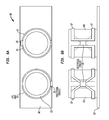
- FIGS. 1A and 1B schematically depict a plan view and side view, respectively, of an illustrative superconducting RF coil array comprising generally circular coils, in accordance with some embodiments of the present invention
- FIGS. 2A and 2B schematically depict a plan view and side view, respectively, of an illustrative superconducting RF coil array comprising generally rectangular coils, in accordance with some embodiments of the present invention
- FIGS. 3A , 3 B, and 3 C schematically illustrate a top view, side view, and oblique view, respectively, of a two-dimensional array of overlapping coil elements, in accordance with some embodiments of the present invention
- FIG. 4A and FIG. 4B schematically depict a plan view and a cross-sectional side view, respectively, of an illustrative superconducting RF coil array which employs high temperature superconductor (HTS) tape for the coils, in accordance with some embodiments of the present invention
- FIG. 5A and FIG. 5B schematically depict a plan view and a side view, respectively, of an illustrative superconducting RF coil array configured for breast imaging in a horizontal main magnetic field, in accordance with some embodiments of the present invention
- FIG. 6A and FIG. 6B schematically depict a plan view and a side view, respectively, of an illustrative superconducting RF coil array configured for breast imaging in a vertical main magnetic field, in accordance with some embodiments of the present invention
- FIG. 7A and FIG. 7B schematically depict a plan view and a side view, respectively, of an illustrative superconducting RF coil array configured for breast imaging in a vertical main magnetic field, in accordance with some embodiments of the present invention
- FIG. 7C and FIG. 7D schematically depict a plan view and a side view, respectively, of an illustrative superconducting RF coil array configured for breast imaging, in accordance with some embodiments of the present invention
- FIGS. 8A and 8B schematically depict an HTS tape coil array comprising a generally cylindrical thermally conductive support and circumferentially disposed overlapping HTS coils, in accordance with some embodiments of the present invention.
- FIGS. 9A and 9B show simulated results of the RF signal profile associated with one HTS coil ( FIG. 9B ) and with a linear array of five overlapping HTS coils according to some embodiments of the present invention.
- cryogenically cooled superconducting RF coil array which may be used in whole-body MRI scanners and/or in dedicated MRI systems (e.g., head-dedicated, limb-dedicated, breast-dedicated, pediatric-dedicated, spine-dedicated, etc.).
- embodiments of the present invention include surface and volume coil array designs and, in various implementations, two or more superconducting coil array modules (e.g., two or more substantially planar coil array modules, such as one or two dimensional surface coil array modules) such as the herein described embodiments (and variations thereof) may be used together (e.g., by independently positioning them and/or by mounting them in a fixed spatial relationship with respect to each other, such as by mechanically coupling them, directly to each other or via one or more intervening support structures) to essentially form a larger array.
- two or more superconducting coil array modules e.g., two or more substantially planar coil array modules, such as one or two dimensional surface coil array modules
- two or more superconducting coil array modules e.g., two or more substantially planar coil array modules, such as one or two dimensional surface coil array modules
- two or more superconducting coil array modules e.g., two or more substantially planar coil array modules, such as one or two dimensional surface coil array modules
- two or more superconducting surface coil array modules may be configured to surround an extremity (e.g., thigh, head, etc.) or the torso (e.g., for cardiac imaging) to provide for imaging over a desired region of interest (ROI) (e.g., the desired field of view (FOV)).
- ROI region of interest
- FOV desired field of view
- each superconducting coil array embodiment having a certain general overall geometry may be configured according to various embodiments for any of a variety of applications, such as for whole-body imaging, head-dedicated imaging, extremity-dedicated imaging, pediatric-dedicated imaging, etc.
- design parameters of the coil array of a given general overall geometry may be varied.
- Such design parameters may include, for example, dimensions of the overall geometric configuration, the dimensions and/or geometry (e.g., circular, square, hexagonal, etc.) and/or number of the coil elements in the array, etc.
- a generally cylindrical array geometry may be applicable for whole-body imaging, head-dedicated imaging, and breast-dedicated imaging; however, if the array is particularly intended for one of these applications, then its design parameters may be determined accordingly (e.g., cylinder length and radius, number and dimensions of coil elements, type of coil elements, spatial arrangement of coil elements about the generally cylindrical geometry, etc.).
- a cylindrical array intended for head-dedicated applications may be arranged such that the cylindrical structure is open at both ends, whereas for breast-dedicated applications one end of the cylindrical structure may be closed (e.g., allowing for a cryocooler to be disposed adjacent to the closed end).
- a cryogenically-cooled superconducting RF coil array coil may be implemented in myriad magnetic resonance imaging and spectroscopy systems, such as systems employing conventional copper gradient coils, systems employing superconducting gradient coils (e.g., such as disclosed in U.S. patent application Ser. No. 12/416,606, filed Apr. 1, 2009, and in Provisional Application No. 61/170,135, filed Apr. 17, 2009, each of which is hereby incorporated by reference in its entirety), whole body systems, dedicated head-only systems, systems with a vertically or horizontally oriented main magnetic field, open or closed systems, etc.
- MRI magnetic resonance
- DTI diffusion tensor imaging
- superconducting coil arrays may be configured or adapted for use as receive-only, or transmit-only, or transmit-and-receive.
- FIGS. 1A and 1B schematically depict a plan view (with the contours of underlying features depicted for clarity) and side view, respectively, of an illustrative superconducting RF coil array 10 , in accordance with some embodiments of the present invention. More specifically, FIGS. 1A and 1B illustrate a configuration of five superconducting RF coil elements 14 a - 14 e (also referred to herein as coils 14 a - 14 e , and collectively as superconductor RF coil elements 14 or coils 14 ) arranged in two layers to provide a linear array.
- coil elements 14 a , 14 c , and 14 e are each disposed in direct thermal contact with a heat conducting substrate (plate) 12
- coil elements 14 b and 14 d are disposed above the lower coil elements and are thermally coupled to the lower coil elements and to the plate 12 via standoffs 16 a and 16 b (referred to collectively as standoffs 16 ), respectively.
- Epoxy and/or thermal grease/compound may be provided between the coils 14 and plate 12 and/or standoffs 16 to provide thermal and mechanical contact therebetween.
- Heat conducting plate 12 and each heat conducting standoff 16 may be formed, for example, of any of one or more high thermal conductivity materials, such as sapphire or alumina, or other non-metallic high thermal conductivity material, such as high thermal conductivity ceramic.
- heat conducting plate 12 is thermally coupled (not shown herein) to a cryogenic cooling system, and superconducting coil array 10 is enclosed within a housing that maintains array 10 within a vacuum (e.g., at least a low vacuum).
- heat conducting plate 12 may be narrower than the diameter of the coil elements and, in some embodiments, plate 12 may be implemented as two separate, parallel elongated members that each contact a backside portion of coil elements 14 a , 14 c , 14 e.
- each coil element 14 comprises a substrate 15 (e.g., a sapphire wafer) and a thin film superconducting coil 17 (also referred to as a trace 17 ).
- substrate 15 e.g., a sapphire wafer
- thin film superconducting coil 17 also referred to as a trace 17 .
- thin film traces 17 are formed on the upper surface (facing away from plate 12 ) of substrates 15 , though in various alternative embodiments the traces may be disposed on the lower surface (facing plate 12 ) of substrates 15 .
- each RF coil element 14 a - 14 e may be implemented as a high temperature superconductor (HTS), such as YBCO and/or BSCCO, etc. (e.g., using an HTS thin film or HTS tape), though a low temperature superconductor (LTS) may be used in various embodiments.
- HTS high temperature superconductor
- LTS low temperature superconductor
- each of RF coil elements 14 a - 14 e is an HTS thin film spiral coil and/or an HTS thin film spiral-interdigitated coil on a substrate such as sapphire or lanthanum aluminate.
- superconducting RF coil array 10 is implemented as an HTS thin film RF coil array.
- each coil element e.g., trace diameter, number of turns
- the design of each coil element may depend on the application, and may include considerations of homogeneity, signal-to-noise ratio, and field of view (FOV). Similar considerations may factor into determining the number of coil elements that will be employed (e.g., while five coil elements are shown in the embodiment of FIGS. 1A and 1B , a linear array may include fewer or more coil elements).
- the traces 17 of neighboring coil elements 14 overlap, with this overlap being provided by vertically displacing neighboring coil elements.
- the amount of overlap between neighboring coils may be optimized with respect to decoupling.
- standoffs 16 may assist in thermal conduction (e.g., between upper coils and plate 12 ) and in mechanical support (e.g., assisting support of the upper coils). Using standoffs 16 a disposed over the traces of the lower coil elements may also assist in preventing damage that may occur to these traces if the upper coil elements directly contacted the lower coil elements. In various embodiments, standoffs 16 a may include a narrow recessed region that is disposed over the underlying trace of the lower coil elements such that the lower trace is not mechanically contacted by the overlying standoff 16 a.
- one or more (e.g., all) of the standoffs 16 may be eliminated.
- some embodiments may include the standoffs 16 a between lower and upper coil elements while not employing standoffs 16 b between plate 12 and upper coil elements 14 b , 14 d , as the inter-coil element standoffs 16 a may provide sufficient thermal conduction for cooling the upper coil elements.
- various embodiments may include an additional high thermal conductivity plate in direct contact with upper coil elements 14 b and 14 d.
- plate 12 may have a thickness of about 3-5 mm
- each coil element trace 17 may have a diameter of about 1 cm to about 10 cm or greater
- each coil element substrate 15 may have a thickness of about 0.3 mm to about 0.6 mm
- standoffs 16 a may have a thickness of about 0.1 mm to about 0.5 mm.
- an electronics module for each coil element may be disposed on plate 12 and/or substrates 15 , and may include at least a preamplifier, and may also include additional circuitry, such as for impedance matching, decoupling, etc.
- superconducting RF coil array 10 depicted in FIGS. 1A and 1B is disposed in a vacuum chamber and is cooled by plate 12 being thermally coupled with a cryogenic cooling system.
- the coils elements 14 a - 14 e may be cooled to a temperature in the range of about 4K to 100K, and more particularly, to a temperature below the critical temperature of the superconducting material (e.g., in some embodiments, below the critical temperature of a high temperature superconductor (HTS) material used for the RF coils 17 ).
- HTS high temperature superconductor
- the cryogenic cooling system may comprise a cryocooler implemented as any of various single stage or multi-stage cryocoolers, such as, for example, a Gifford McMahon (GM) cryocooler, a pulse tube (PT) cooler, a Joule-Thomson (JT) cooler, a Stirling cooler, or other cryocooler.
- GM Gifford McMahon
- PT pulse tube
- JT Joule-Thomson
- the superconductor RF coil array 10 may be configured for cooling such that coils 17 are cooled by a cryogen, such as liquid helium and liquid nitrogen.
- the vacuum chamber may be implemented, for example, as a double-walled Dewar structure. More specifically, in accordance with some embodiments of the present invention, the vacuum chamber may comprise a double-walled Dewar made of glass and/or other non-conductive, mechanically strong material(s), such as G10, RF4, plastic, and/or ceramic.
- a double-walled Dewar may be implemented in accordance with, or similar to, the hermetically sealed double-walled structures (and vacuum thermal isolation housing) described in U.S. application Ser. No. 12/212,122, filed Sep. 17, 2008, in U.S. application Ser. No. 12/212,147, filed Sep. 17, 2008, and in U.S. Provisional application Ser. No.
- two or more linear arrays such as, or in accordance with, the linear array depicted in FIGS. 1A and 1B may be combined to provide a two or three dimensional array assembly.
- eight linear arrays e.g., each having two or more linearly arranged coil elements
- each linear array extending longitudinally, and azimuthally displaced by about 45 degrees.
- Such a configuration may be implemented similarly to embodiments of the superconductor RF head coil array disclosed in Provisional Application No. 61/171,074, filed Apr. 20, 2009, which is herein incorporated by reference in its entirety.
- superconducting RF coil array 10 may be implemented as a receive-only array, with an RF transmitter being implemented as a separate RF coil (not shown), which in various embodiments may be a conventional (e.g., non-superconducting, such as a conventional copper RF coil) RF transmitter coil or a superconducting RF transmitting coil.
- superconducting RF coil array 10 may be implemented as a transmit and receive coil array (a transceiver array), with each superconducting RF coil element 14 being used for both transmission and reception of RF signals.
- one or more of the superconducting RF coil elements 14 may be implemented as a multiple resonance RF coil element (e.g., comprising two or more receiving coils having different resonant frequencies, such as for detecting sodium and hydrogen resonances at a given magnetic field (e.g., at 3 Tesla (T)).
- a multiple resonance RF coil element e.g., comprising two or more receiving coils having different resonant frequencies, such as for detecting sodium and hydrogen resonances at a given magnetic field (e.g., at 3 Tesla (T)).
- FIGS. 2A and 2B shown are a plan view (with the contours of underlying features depicted for clarity) and side view, respectively, of an illustrative superconducting RF coil array 20 , in accordance with some embodiments of the present invention. More specifically, FIGS. 2A and 2B illustrate a configuration of five superconducting RF coil elements 24 a - 24 e (referred to herein collectively as superconductor RF coil elements 24 or coils 24 ) arranged in two layers to provide a linear array, similar to the linear array of FIGS. 1A and 1B , formed on a heat conducting plate 22 . Compared to the linear array of FIGS. 1A and 1B , the linear array of FIGS.
- Rectangular substrates 25 may be formed by cutting or scribing a circular substrate, such as a circular sapphire or alumina substrate. Rectangular shaped traces may provide for improved image reconstruction due to the substantially constant trace overlap distance. Rectangular coil elements may also be better suited than circular coil elements for forming two-dimensional arrays.
- FIGS. 3A-3C illustrate a two-dimensional (2 ⁇ 5) rectangular array 30 of substantially rectangular coil elements 34 a 1 , 34 b 1 . . . 34 e 1 , 34 a 2 , 34 b 2 . . . 34 e 2 , having substantially rectangular substrates and substantially rectangular traces 37 , assembled in four layers using a standoff element 36 directly coupled between heat conducting plate 32 and the coil elements of the second uppermost layer (comprising elements 34 a 2 , 34 c 2 , and 34 e 2 ), thereby providing thermal conduction and mechanical support for the elements of the second uppermost layer and those of the overlying uppermost layer (comprising elements 34 b 2 , 34 d 2 ). More specifically, FIG.
- FIG. 3A is a top view (with the contours of underlying features depicted for clarity), FIG. 3B is a side view, and FIG. 3C is an oblique view (with the contours of underlying features depicted for clarity).
- the traces 37 of each adjacent coil element overlap each other (i.e., a coil element trace overlaps the traces of its nearest neighbors and next-nearest neighbors (i.e., diagonally disposed neighbors).
- standoff disk elements may also be included to directly couple elements of the lowermost layer (comprising elements 34 a 1 , 34 c 1 , 34 e 1 ) and elements of the second uppermost layer (comprising elements 34 a 2 , 34 c 2 , and 34 e 2 ) in regions where the lowermost layer elements and second uppermost layer elements overlap.
- standoff disks may be disposed between plate 32 and each of coil elements 34 a 2 , 34 c 2 , and 34 e 2 .
- FIGS. 3A-3C may be used to provide a two-dimensional array of overlapping coil elements of arbitrary dimension (e.g., 3 ⁇ 5, 4 ⁇ 5, 4 ⁇ 8, 8 ⁇ 8, etc.).
- FIG. 4A and FIG. 4B shown are a plan view (with the contours of underlying features depicted for clarity) and a cross-sectional side view (sectioned along the diameter of coil elements), respectively, of an illustrative superconducting RF coil array 40 which employs high temperature superconductor (HTS) tape for the coils, in accordance with some embodiments of the present invention.
- array 40 comprises three linearly arranged coil elements 44 a , 44 b , 44 c , alternately disposed on opposite surfaces of heat conducting plate 42 .
- Each coil element comprises a thermally conductive (e.g., alumina) supporting ring 43 , an HTS coil 47 , and an electrical circuit 49 .
- thermally conductive (e.g., alumina) supporting ring 43 is thermally coupled to heat conducting (e.g., alumina or sapphire) plate 42 , and HTS tape 47 is wrapped circumferentially around alumina supporting ring 43 and may be fixed in place by attachment (e.g., soldering) of electrical circuit 49 .
- Epoxy and/or thermal grease may also be used to thermally couple and affix tape 47 to the circumferential surface of supporting ring 43 .
- Electrical circuit 49 may include at least a preamplifier, and may also include additional circuitry, such as for impedance matching, decoupling, etc.
- ring 43 may have a diameter between about 2.5 cm to about 25 cm or greater, and may have a height (along cylindrical axis) of about 5 mm to about 25 mm; HTS tape 47 may have a thickness of about 0.1 mm to about 0.5 mm and a width of about 5 mm to about 13 mm and may be wrapped a single loop around alumina ring 43 .
- FIG. 5A and FIG. 5B shown are a plan view (with the contours of underlying features depicted for clarity) and a side view, respectively, of an illustrative superconducting RF coil array 50 which employs high temperature superconductor (HTS) tape for the coils and is configured for breast imaging in a horizontal main magnetic field (i.e., orthogonal to the longitudinal axis of the generally cylindrically shaped coil elements), in accordance with some embodiments of the present invention.
- the construction of coil array 50 is similar to coil array 40 at least insofar as the coil elements are implemented as HTS tape mounted about a generally cylindrical thermally conductive (e.g., alumina) support ring which is thermally coupled to a heat conducting plate.
- HTS high temperature superconductor
- each generally cylindrical coil element of array 50 comprises a thermally conductive (e.g., alumina) supporting ring 53 , an HTS coil 57 , and an electrical circuit 59 .
- thermally conductive (e.g., alumina) supporting ring 53 is thermally coupled to heat conducting (e.g., alumina or sapphire) plate 52
- HTS tape 57 is wrapped circumferentially around alumina supporting ring 53 in a coil configuration for use with a horizontal magnetic field, and may be fixed in place by attachment (e.g., soldering) of electrical circuit 59 .
- Epoxy and/or thermal grease may also be used to thermally couple and affix tape 57 to the circumferential surface of supporting ring 53 .
- Electrical circuit 59 may include at least a preamplifier, and may also include additional circuitry, such as for impedance matching, decoupling, etc.
- ring 43 may have a diameter of about 15 cm to about 25 cm or greater, and may have a height (along cylindrical axis) of about 15 cm to about 25 cm or greater.
- FIG. 6A and FIG. 6B shown are a plan view (with the contours of underlying features depicted for clarity) and a side view, respectively, of an illustrative superconducting RF coil array 60 which employs high temperature superconductor (HTS) tape for the coils and is configured for breast imaging in a vertical main magnetic field (i.e., parallel to the longitudinal axis of the generally cylindrically shaped coil elements), in accordance with some embodiments of the present invention.
- HTS high temperature superconductor
- each generally cylindrical coil element of array 60 comprises a thermally conductive (e.g., alumina) supporting ring 63 , an HTS coil 67 , and an electrical circuit 69 , and the thermally conductive (e.g., alumina) supporting ring 63 is thermally coupled to heat conducting (e.g., alumina or sapphire) plate 62 .
- the construction of coil array 60 is similar to coil array 50 ; however, HTS coils 67 are wound in a configuration suitable for use in a vertical field (e.g., a saddle coil configuration).
- FIG. 7A and FIG. 7B shown are a plan view (with the contours of underlying features depicted for clarity) and a side view, respectively, of an illustrative superconducting RF coil array 70 which employs high temperature superconductor (HTS) tape for the coils and is configured for breast imaging in a vertical main magnetic field (i.e., parallel to the longitudinal axis of the generally cylindrically shaped coil elements), in accordance with some embodiments of the present invention.
- HTS high temperature superconductor
- each generally cylindrical coil element of array 70 comprises a thermally conductive (e.g., alumina) supporting ring 73 , HTS tape 77 , and an electrical circuit 79 , and the thermally conductive (e.g., alumina) supporting ring 73 is thermally coupled to heat conducting (e.g., alumina or sapphire) plate 72 .
- the construction of coil array 70 is similar to coil array 60 ; however, the HTS tape 77 associated with each supporting ring is implemented as two overlapping coils to provide a coil array for each generally cylindrical element.
- overlapping HTS coils 77 a 1 (upper) and 77 b 1 (lower) are wound on one common supporting ring 73
- overlapping HTS coils 77 a 2 (upper) and 77 b 2 (lower) are wound on the other common supporting ring 73
- Electrical insulators 71 are disposed where the upper and lower coils overlap to separate the overlapping upper and lower coils.
- the coil group 77 a 1 / 77 b 1 and group 77 a 2 / 77 b 2 can be arranged such that their respective associated fields (B1 field) are orthogonal with each other to minimize the coupling between them, as shown in FIG. 7C and FIG. 7D .
- FIGS. 8A and 8B schematically depict an HTS tape coil array comprising a generally cylindrical thermally conductive support (e.g., alumina tube) 83 and HTS coils ( 87 ) implemented as HTS tape and formed on the alumina tube directly or through a thin plastic sheet, in accordance with some embodiments of the present invention. More specifically, FIG. 8B depicts the overlapping six element coil array configuration that is circumferentially disposed about support 83 . As noted, high temperature superconductor (HTS) tape is used for the coils, in accordance with various embodiments. Additionally, as shown, electrical insulators (dielectric spacers) 81 are disposed where the coils overlap to separate the overlapping coils.
- HTS high temperature superconductor
- FIGS. 9A and 9B show simulated results of the RF signal profile associated with one HTS coil ( FIG. 9A ) and with a linear array of five overlapping HTS coils, illustrating the uniformity that may be provided by such arrays.
- a cryogenically-cooled superconducting RF coil array coil may be implemented in a magnetic resonance imaging system that employs superconducting gradient coils such as those disclosed in U.S. patent application Ser. No. 12/416,606, filed Apr. 1, 2009, and in Provisional Application No. 61/170,135, filed Apr. 17, 2009, each of which is hereby incorporated by reference in its entirety.
Priority Applications (2)
| Application Number | Priority Date | Filing Date | Title |
|---|---|---|---|
| US12/887,474 US8723522B2 (en) | 2009-09-21 | 2010-09-21 | Superconductor RF coil array |
| US14/276,942 US20150077116A1 (en) | 2009-09-21 | 2014-05-13 | Superconductor RF Coil Array |
Applications Claiming Priority (2)
| Application Number | Priority Date | Filing Date | Title |
|---|---|---|---|
| US24413209P | 2009-09-21 | 2009-09-21 | |
| US12/887,474 US8723522B2 (en) | 2009-09-21 | 2010-09-21 | Superconductor RF coil array |
Related Child Applications (1)
| Application Number | Title | Priority Date | Filing Date |
|---|---|---|---|
| US14/276,942 Continuation US20150077116A1 (en) | 2009-09-21 | 2014-05-13 | Superconductor RF Coil Array |
Publications (2)
| Publication Number | Publication Date |
|---|---|
| US20110121830A1 US20110121830A1 (en) | 2011-05-26 |
| US8723522B2 true US8723522B2 (en) | 2014-05-13 |
Family
ID=43302905
Family Applications (2)
| Application Number | Title | Priority Date | Filing Date |
|---|---|---|---|
| US12/887,474 Active 2031-10-23 US8723522B2 (en) | 2009-09-21 | 2010-09-21 | Superconductor RF coil array |
| US14/276,942 Abandoned US20150077116A1 (en) | 2009-09-21 | 2014-05-13 | Superconductor RF Coil Array |
Family Applications After (1)
| Application Number | Title | Priority Date | Filing Date |
|---|---|---|---|
| US14/276,942 Abandoned US20150077116A1 (en) | 2009-09-21 | 2014-05-13 | Superconductor RF Coil Array |
Country Status (9)
| Country | Link |
|---|---|
| US (2) | US8723522B2 (ru) |
| EP (1) | EP2480906A1 (ru) |
| JP (2) | JP5893560B2 (ru) |
| CN (1) | CN102812377B (ru) |
| BR (1) | BR112012006367A2 (ru) |
| CA (1) | CA2774983A1 (ru) |
| MX (1) | MX2012003415A (ru) |
| RU (1) | RU2012116148A (ru) |
| WO (1) | WO2011035333A1 (ru) |
Cited By (7)
| Publication number | Priority date | Publication date | Assignee | Title |
|---|---|---|---|---|
| US20120286786A1 (en) * | 2011-05-09 | 2012-11-15 | Wayne Schellekens | Phased Array MR RF Coil Which is Not Visible in X-Ray Image |
| US20120319690A1 (en) * | 2009-03-10 | 2012-12-20 | Qiyuan Ma | Superconductor Magnetic Resonance Imaging System and Method (SUPER-MRI) |
| US20130063148A1 (en) * | 2011-05-10 | 2013-03-14 | Qiyuan Ma | Cryogenically Cooled Whole-Body RF Coil Array and MRI System Having Same |
| US20150077116A1 (en) * | 2009-09-21 | 2015-03-19 | Time Medical Holdings Company Limited | Superconductor RF Coil Array |
| US20150241528A1 (en) * | 2014-02-27 | 2015-08-27 | Andreas Fackelmeier | Transmitting and/or Receiving MRI Signals for a MRI Examination |
| US20170287625A1 (en) * | 2014-12-11 | 2017-10-05 | Ckd Corporation | Coil cooling structure |
| US20180045794A1 (en) * | 2016-04-22 | 2018-02-15 | New York University | Trellis coil arrangement and methods for use thereof |
Families Citing this family (13)
| Publication number | Priority date | Publication date | Assignee | Title |
|---|---|---|---|---|
| TWI449256B (zh) * | 2010-08-19 | 2014-08-11 | Ind Tech Res Inst | 電磁傳遞裝置 |
| DE102011006164B8 (de) * | 2011-03-25 | 2013-04-18 | Bruker Biospin Ag | Kompakter kryogener NMR-Sensor mit integriertem, aktivem Kühlaggregat |
| US9519037B2 (en) * | 2011-11-10 | 2016-12-13 | Mayo Foundation For Medical Education And Research | Spatially coincident MRI receiver coils and method for manufacturing |
| US9971001B2 (en) * | 2011-11-28 | 2018-05-15 | The Texas A&M University System | Volume array coil with enforced uniform element currents for improved excitation homogeneity |
| US10209325B2 (en) * | 2016-02-29 | 2019-02-19 | Siemens Healthcare Gmbh | Magnetic resonance imaging coil with adjustable opening |
| US10132883B2 (en) * | 2016-05-31 | 2018-11-20 | General Electric Company | Foldable coil array |
| CN109963507B (zh) * | 2016-11-23 | 2023-07-04 | 通用电气公司 | 用于磁共振成像(mri)系统的前部射频(rf)线圈阵列 |
| JP7171566B2 (ja) * | 2016-11-23 | 2022-11-15 | ゼネラル・エレクトリック・カンパニイ | Mrイメージング用の無線周波数コイルのシステム |
| KR102270520B1 (ko) * | 2016-11-23 | 2021-06-30 | 제너럴 일렉트릭 캄파니 | 자기 공명 이미징(mri) 시스템을 위한 순응성 후방 무선 주파수(rf) 코일 어레이 |
| KR101806198B1 (ko) * | 2016-12-30 | 2017-12-08 | 연세대학교 산학협력단 | 무선 주파수 코일 및 이를 포함하는 의료용 영상 장치 |
| CN110169772A (zh) * | 2019-06-26 | 2019-08-27 | 苏州众志医疗科技有限公司 | 一种水平场磁共振介入专用射频阵列线圈装置及其使用方法 |
| CN110940945B (zh) * | 2019-12-02 | 2020-11-03 | 浙江大学 | 具有高时域信号稳定性的磁共振成像射频线圈组件 |
| CN116997807A (zh) * | 2021-01-15 | 2023-11-03 | 海珀菲纳运营有限公司 | 用于磁共振成像的柔性射频线圈设备和方法 |
Citations (13)
| Publication number | Priority date | Publication date | Assignee | Title |
|---|---|---|---|---|
| US6169399B1 (en) * | 1996-12-02 | 2001-01-02 | The Trustees Of Columbia University In The City Of New York | Multiple resonance superconducting probe |
| US6377836B1 (en) | 1999-02-17 | 2002-04-23 | Toshiba America Mri, Inc. | RF coil array for vertical field MRI |
| WO2004038431A2 (en) | 2002-10-24 | 2004-05-06 | The University Of Houston System | Superconducting array of surface mri probes |
| WO2004086074A1 (en) | 2003-03-27 | 2004-10-07 | Oxford Instruments Superconductivity Limited | Nmr apparatus for concurrent analysis of multiple samples using a receiver coil array |
| WO2005052621A1 (en) | 2003-11-25 | 2005-06-09 | Koninklijke Philips Electronics, N.V. | Magnetic resonance coil element with embedded electronics module |
| US20060033498A1 (en) | 2004-08-11 | 2006-02-16 | Kazuo Saitoh | Nuclear magnetic resonance apparatus |
| US7138801B2 (en) * | 2004-12-08 | 2006-11-21 | Hitachi, Ltd. | NMR spectrometer and NMR probe |
| US20070273379A1 (en) | 2006-05-25 | 2007-11-29 | Hitachi, Ltd. | Nuclear Magnetic resonance probe coil |
| US20080111548A1 (en) | 2006-11-09 | 2008-05-15 | Hiroyuki Yamamoto | Nmr probe and nmr spectrometer |
| US20090134873A1 (en) | 2007-11-22 | 2009-05-28 | Gachon University Of Medicine & Science Industry- Academic Cooperation Foundation | Rf coil assembly for magnetic resonance imaging system |
| US7728592B2 (en) * | 2008-09-17 | 2010-06-01 | Time Medical Holdings Company Limited | Integrated superconductor MRI imaging system |
| US7772842B2 (en) * | 2008-09-17 | 2010-08-10 | Time Medical Holdings Company Limited | Dedicated superconductor MRI imaging system |
| US7859264B2 (en) * | 2004-01-20 | 2010-12-28 | The University Of Houston | Superconducting loop, saddle and birdcage MRI coils capable of simultaneously imaging small nonhuman animals |
Family Cites Families (9)
| Publication number | Priority date | Publication date | Assignee | Title |
|---|---|---|---|---|
| NL8603006A (nl) * | 1986-11-27 | 1988-06-16 | Philips Nv | Magnetisch resonantie apparaat met gestapeld oppervlakte spoelenstelsel. |
| US4943775A (en) * | 1986-11-27 | 1990-07-24 | U.S. Philips Corporation | Magnetic resonance apparatus with uncoupled rf coils |
| US5914600A (en) * | 1997-06-04 | 1999-06-22 | Brigham And Women's Hospital | Planar open solenoidal magnet MRI system |
| CN1268756A (zh) * | 1999-03-24 | 2000-10-04 | 浙江亚克科技有限公司 | 一种高温超导线圈及其磁共振仪 |
| US20050062473A1 (en) * | 2003-09-24 | 2005-03-24 | General Electric Company | Cryogen-free high temperature superconducting magnet with thermal reservoir |
| US7970452B2 (en) * | 2003-09-30 | 2011-06-28 | Hologic, Inc. | Open architecture imaging apparatus and coil system for magnetic resonance imaging |
| US7167000B2 (en) * | 2004-12-22 | 2007-01-23 | General Electric Company | Cryogenically cooled radiofrequency coil array for magnetic resonance imaging |
| DE102006046888B4 (de) * | 2006-10-04 | 2010-12-16 | Bruker Biospin Ag | Gekühlter Magnet-Resonanz-Probenkopf mit einem Vakuumbehälter sowie zugehörige NMR-Messapparatur |
| EP2480906A1 (en) * | 2009-09-21 | 2012-08-01 | Time Medical Holdings Company Limited | Superconductor rf coil array |
-
2010
- 2010-09-21 EP EP20100770658 patent/EP2480906A1/en not_active Withdrawn
- 2010-09-21 US US12/887,474 patent/US8723522B2/en active Active
- 2010-09-21 BR BR112012006367A patent/BR112012006367A2/pt not_active Application Discontinuation
- 2010-09-21 JP JP2012530981A patent/JP5893560B2/ja not_active Expired - Fee Related
- 2010-09-21 CN CN201080050898.3A patent/CN102812377B/zh active Active
- 2010-09-21 WO PCT/US2010/049719 patent/WO2011035333A1/en active Application Filing
- 2010-09-21 MX MX2012003415A patent/MX2012003415A/es not_active Application Discontinuation
- 2010-09-21 CA CA2774983A patent/CA2774983A1/en not_active Abandoned
- 2010-09-21 RU RU2012116148/28A patent/RU2012116148A/ru unknown
-
2014
- 2014-05-13 US US14/276,942 patent/US20150077116A1/en not_active Abandoned
-
2015
- 2015-09-25 JP JP2015188567A patent/JP2016028710A/ja active Pending
Patent Citations (15)
| Publication number | Priority date | Publication date | Assignee | Title |
|---|---|---|---|---|
| US6169399B1 (en) * | 1996-12-02 | 2001-01-02 | The Trustees Of Columbia University In The City Of New York | Multiple resonance superconducting probe |
| US6377836B1 (en) | 1999-02-17 | 2002-04-23 | Toshiba America Mri, Inc. | RF coil array for vertical field MRI |
| WO2004038431A2 (en) | 2002-10-24 | 2004-05-06 | The University Of Houston System | Superconducting array of surface mri probes |
| WO2004086074A1 (en) | 2003-03-27 | 2004-10-07 | Oxford Instruments Superconductivity Limited | Nmr apparatus for concurrent analysis of multiple samples using a receiver coil array |
| WO2005052621A1 (en) | 2003-11-25 | 2005-06-09 | Koninklijke Philips Electronics, N.V. | Magnetic resonance coil element with embedded electronics module |
| US7859264B2 (en) * | 2004-01-20 | 2010-12-28 | The University Of Houston | Superconducting loop, saddle and birdcage MRI coils capable of simultaneously imaging small nonhuman animals |
| US8106656B2 (en) * | 2004-01-20 | 2012-01-31 | The University Of Houston System | Superconducting loop, saddle and birdcage MRI coils |
| US20060033498A1 (en) | 2004-08-11 | 2006-02-16 | Kazuo Saitoh | Nuclear magnetic resonance apparatus |
| US7173424B2 (en) * | 2004-08-11 | 2007-02-06 | Hitachi, Ltd. | Nuclear magnetic resonance apparatus |
| US7138801B2 (en) * | 2004-12-08 | 2006-11-21 | Hitachi, Ltd. | NMR spectrometer and NMR probe |
| US20070273379A1 (en) | 2006-05-25 | 2007-11-29 | Hitachi, Ltd. | Nuclear Magnetic resonance probe coil |
| US20080111548A1 (en) | 2006-11-09 | 2008-05-15 | Hiroyuki Yamamoto | Nmr probe and nmr spectrometer |
| US20090134873A1 (en) | 2007-11-22 | 2009-05-28 | Gachon University Of Medicine & Science Industry- Academic Cooperation Foundation | Rf coil assembly for magnetic resonance imaging system |
| US7728592B2 (en) * | 2008-09-17 | 2010-06-01 | Time Medical Holdings Company Limited | Integrated superconductor MRI imaging system |
| US7772842B2 (en) * | 2008-09-17 | 2010-08-10 | Time Medical Holdings Company Limited | Dedicated superconductor MRI imaging system |
Non-Patent Citations (4)
| Title |
|---|
| International Preliminary Report on Patentability mailed Mar. 27, 2012 in International Application No. PCT/US2010/049719, filed Sep. 21, 2010. |
| Jean-Christophe Ginefri et al., "Technical aspects: Development, manufacture and installation of a cryo-cooled HTS coil system for high-resolution in-vivo imaging of the mouse at 1.5 T," Methods, Aug. 23, 2007, pp. 54-67, vol. 43, Issue 1. |
| M.S. Chow et al., "A Two-Channel HTS Thin-Film Phases Array Coil for Low Field MRI," Int'l Society for Magnetic Resonance in Medicine, Scientific Meeting and Exhibition, Proceedings, Int'l Society for Magnetic Resonance in Medicine, US, Jul. 10, 2003, p. 2372. |
| PCT International Search Report mailed Jan. 28, 2011 in International Application No. PCT/US2010/049719, filed Sep. 21, 2010. |
Cited By (12)
| Publication number | Priority date | Publication date | Assignee | Title |
|---|---|---|---|---|
| US20120319690A1 (en) * | 2009-03-10 | 2012-12-20 | Qiyuan Ma | Superconductor Magnetic Resonance Imaging System and Method (SUPER-MRI) |
| US9869733B2 (en) * | 2009-03-10 | 2018-01-16 | Time Medical Holdings Company Limited | Superconductor magnetic resonance imaging system and method (super-MRI) |
| US20150077116A1 (en) * | 2009-09-21 | 2015-03-19 | Time Medical Holdings Company Limited | Superconductor RF Coil Array |
| US20120286786A1 (en) * | 2011-05-09 | 2012-11-15 | Wayne Schellekens | Phased Array MR RF Coil Which is Not Visible in X-Ray Image |
| US9081067B2 (en) * | 2011-05-09 | 2015-07-14 | Imris Inc. | Phased array MR RF coil which is not visible in X-ray image |
| US20130063148A1 (en) * | 2011-05-10 | 2013-03-14 | Qiyuan Ma | Cryogenically Cooled Whole-Body RF Coil Array and MRI System Having Same |
| US9170310B2 (en) * | 2011-05-10 | 2015-10-27 | Time Medical Holdings Company Limited | Cryogenically cooled whole-body RF coil array and MRI system having same |
| US20150241528A1 (en) * | 2014-02-27 | 2015-08-27 | Andreas Fackelmeier | Transmitting and/or Receiving MRI Signals for a MRI Examination |
| US10094894B2 (en) * | 2014-02-27 | 2018-10-09 | Siemens Aktiengesellschaft | Transmitting and/or receiving MRI signals for a MRI examination |
| US20170287625A1 (en) * | 2014-12-11 | 2017-10-05 | Ckd Corporation | Coil cooling structure |
| US20180045794A1 (en) * | 2016-04-22 | 2018-02-15 | New York University | Trellis coil arrangement and methods for use thereof |
| US10551448B2 (en) * | 2016-04-22 | 2020-02-04 | New York University | Trellis coil arrangement and methods for use thereof |
Also Published As
| Publication number | Publication date |
|---|---|
| CA2774983A1 (en) | 2011-03-24 |
| JP2013505111A (ja) | 2013-02-14 |
| CN102812377B (zh) | 2016-12-07 |
| MX2012003415A (es) | 2012-06-19 |
| US20110121830A1 (en) | 2011-05-26 |
| JP2016028710A (ja) | 2016-03-03 |
| CN102812377A (zh) | 2012-12-05 |
| WO2011035333A1 (en) | 2011-03-24 |
| BR112012006367A2 (pt) | 2016-03-29 |
| JP5893560B2 (ja) | 2016-03-23 |
| EP2480906A1 (en) | 2012-08-01 |
| US20150077116A1 (en) | 2015-03-19 |
| RU2012116148A (ru) | 2013-10-27 |
Similar Documents
| Publication | Publication Date | Title |
|---|---|---|
| US8723522B2 (en) | Superconductor RF coil array | |
| US20110015078A1 (en) | Cryogenically cooled superconductor rf head coil array and head-only magnetic resonance imaging (mri) system using same | |
| US9869733B2 (en) | Superconductor magnetic resonance imaging system and method (super-MRI) | |
| US8593146B2 (en) | Cryogenically cooled superconductor gradient coil module for magnetic resonance imaging | |
| US7772842B2 (en) | Dedicated superconductor MRI imaging system | |
| US9170310B2 (en) | Cryogenically cooled whole-body RF coil array and MRI system having same | |
| US7728592B2 (en) | Integrated superconductor MRI imaging system | |
| WO2011060699A1 (zh) | 适用于磁共振成像的低温冷却的超导体梯度线圈模块 | |
| CN103105595A (zh) | 一种液氮制冷的磁共振成像系统 | |
| CN203149098U (zh) | 一种液氮制冷的磁共振成像系统 |
Legal Events
| Date | Code | Title | Description |
|---|---|---|---|
| AS | Assignment |
Owner name: TIME MEDICAL HOLDINGS COMPANY LIMITED, HONG KONG Free format text: ASSIGNMENT OF ASSIGNORS INTEREST;ASSIGNORS:MA, QIYUAN;GAO, ERZHEN;REEL/FRAME:027893/0062 Effective date: 20100921 |
|
| STCF | Information on status: patent grant |
Free format text: PATENTED CASE |
|
| FEPP | Fee payment procedure |
Free format text: SURCHARGE FOR LATE PAYMENT, SMALL ENTITY (ORIGINAL EVENT CODE: M2554) |
|
| MAFP | Maintenance fee payment |
Free format text: PAYMENT OF MAINTENANCE FEE, 4TH YR, SMALL ENTITY (ORIGINAL EVENT CODE: M2551) Year of fee payment: 4 |
|
| MAFP | Maintenance fee payment |
Free format text: PAYMENT OF MAINTENANCE FEE, 8TH YR, SMALL ENTITY (ORIGINAL EVENT CODE: M2552); ENTITY STATUS OF PATENT OWNER: SMALL ENTITY Year of fee payment: 8 |