US8720468B2 - Pouch air valve and structure adopted on a sealed pouch and method of use - Google Patents
Pouch air valve and structure adopted on a sealed pouch and method of use Download PDFInfo
- Publication number
- US8720468B2 US8720468B2 US13/219,992 US201113219992A US8720468B2 US 8720468 B2 US8720468 B2 US 8720468B2 US 201113219992 A US201113219992 A US 201113219992A US 8720468 B2 US8720468 B2 US 8720468B2
- Authority
- US
- United States
- Prior art keywords
- air valve
- pouch
- hollow tube
- suction
- suction plate
- Prior art date
- Legal status (The legal status is an assumption and is not a legal conclusion. Google has not performed a legal analysis and makes no representation as to the accuracy of the status listed.)
- Active, expires
Links
Images



Classifications
-
- B—PERFORMING OPERATIONS; TRANSPORTING
- B65—CONVEYING; PACKING; STORING; HANDLING THIN OR FILAMENTARY MATERIAL
- B65D—CONTAINERS FOR STORAGE OR TRANSPORT OF ARTICLES OR MATERIALS, e.g. BAGS, BARRELS, BOTTLES, BOXES, CANS, CARTONS, CRATES, DRUMS, JARS, TANKS, HOPPERS, FORWARDING CONTAINERS; ACCESSORIES, CLOSURES, OR FITTINGS THEREFOR; PACKAGING ELEMENTS; PACKAGES
- B65D81/00—Containers, packaging elements, or packages, for contents presenting particular transport or storage problems, or adapted to be used for non-packaging purposes after removal of contents
- B65D81/18—Containers, packaging elements, or packages, for contents presenting particular transport or storage problems, or adapted to be used for non-packaging purposes after removal of contents providing specific environment for contents, e.g. temperature above or below ambient
- B65D81/20—Containers, packaging elements, or packages, for contents presenting particular transport or storage problems, or adapted to be used for non-packaging purposes after removal of contents providing specific environment for contents, e.g. temperature above or below ambient under vacuum or superatmospheric pressure, or in a special atmosphere, e.g. of inert gas
- B65D81/2046—Containers, packaging elements, or packages, for contents presenting particular transport or storage problems, or adapted to be used for non-packaging purposes after removal of contents providing specific environment for contents, e.g. temperature above or below ambient under vacuum or superatmospheric pressure, or in a special atmosphere, e.g. of inert gas under superatmospheric pressure
- B65D81/2061—Containers, packaging elements, or packages, for contents presenting particular transport or storage problems, or adapted to be used for non-packaging purposes after removal of contents providing specific environment for contents, e.g. temperature above or below ambient under vacuum or superatmospheric pressure, or in a special atmosphere, e.g. of inert gas under superatmospheric pressure in a flexible container
-
- B—PERFORMING OPERATIONS; TRANSPORTING
- B65—CONVEYING; PACKING; STORING; HANDLING THIN OR FILAMENTARY MATERIAL
- B65B—MACHINES, APPARATUS OR DEVICES FOR, OR METHODS OF, PACKAGING ARTICLES OR MATERIALS; UNPACKING
- B65B31/00—Packaging articles or materials under special atmospheric or gaseous conditions; Adding propellants to aerosol containers
- B65B31/04—Evacuating, pressurising or gasifying filled containers or wrappers by means of nozzles through which air or other gas, e.g. an inert gas, is withdrawn or supplied
- B65B31/046—Evacuating, pressurising or gasifying filled containers or wrappers by means of nozzles through which air or other gas, e.g. an inert gas, is withdrawn or supplied the nozzles co-operating, or being combined, with a device for opening or closing the container or wrapper
- B65B31/047—Evacuating, pressurising or gasifying filled containers or wrappers by means of nozzles through which air or other gas, e.g. an inert gas, is withdrawn or supplied the nozzles co-operating, or being combined, with a device for opening or closing the container or wrapper the nozzles co-operating with a check valve in the opening of the container or wrapper
-
- B—PERFORMING OPERATIONS; TRANSPORTING
- B65—CONVEYING; PACKING; STORING; HANDLING THIN OR FILAMENTARY MATERIAL
- B65D—CONTAINERS FOR STORAGE OR TRANSPORT OF ARTICLES OR MATERIALS, e.g. BAGS, BARRELS, BOTTLES, BOXES, CANS, CARTONS, CRATES, DRUMS, JARS, TANKS, HOPPERS, FORWARDING CONTAINERS; ACCESSORIES, CLOSURES, OR FITTINGS THEREFOR; PACKAGING ELEMENTS; PACKAGES
- B65D81/00—Containers, packaging elements, or packages, for contents presenting particular transport or storage problems, or adapted to be used for non-packaging purposes after removal of contents
- B65D81/18—Containers, packaging elements, or packages, for contents presenting particular transport or storage problems, or adapted to be used for non-packaging purposes after removal of contents providing specific environment for contents, e.g. temperature above or below ambient
- B65D81/20—Containers, packaging elements, or packages, for contents presenting particular transport or storage problems, or adapted to be used for non-packaging purposes after removal of contents providing specific environment for contents, e.g. temperature above or below ambient under vacuum or superatmospheric pressure, or in a special atmosphere, e.g. of inert gas
- B65D81/2007—Containers, packaging elements, or packages, for contents presenting particular transport or storage problems, or adapted to be used for non-packaging purposes after removal of contents providing specific environment for contents, e.g. temperature above or below ambient under vacuum or superatmospheric pressure, or in a special atmosphere, e.g. of inert gas under vacuum
- B65D81/2038—Containers, packaging elements, or packages, for contents presenting particular transport or storage problems, or adapted to be used for non-packaging purposes after removal of contents providing specific environment for contents, e.g. temperature above or below ambient under vacuum or superatmospheric pressure, or in a special atmosphere, e.g. of inert gas under vacuum with means for establishing or improving vacuum
-
- Y—GENERAL TAGGING OF NEW TECHNOLOGICAL DEVELOPMENTS; GENERAL TAGGING OF CROSS-SECTIONAL TECHNOLOGIES SPANNING OVER SEVERAL SECTIONS OF THE IPC; TECHNICAL SUBJECTS COVERED BY FORMER USPC CROSS-REFERENCE ART COLLECTIONS [XRACs] AND DIGESTS
- Y10—TECHNICAL SUBJECTS COVERED BY FORMER USPC
- Y10T—TECHNICAL SUBJECTS COVERED BY FORMER US CLASSIFICATION
- Y10T137/00—Fluid handling
- Y10T137/0318—Processes
- Y10T137/0402—Cleaning, repairing, or assembling
- Y10T137/0491—Valve or valve element assembling, disassembling, or replacing
- Y10T137/0497—Fluid actuated or retarded
-
- Y—GENERAL TAGGING OF NEW TECHNOLOGICAL DEVELOPMENTS; GENERAL TAGGING OF CROSS-SECTIONAL TECHNOLOGIES SPANNING OVER SEVERAL SECTIONS OF THE IPC; TECHNICAL SUBJECTS COVERED BY FORMER USPC CROSS-REFERENCE ART COLLECTIONS [XRACs] AND DIGESTS
- Y10—TECHNICAL SUBJECTS COVERED BY FORMER USPC
- Y10T—TECHNICAL SUBJECTS COVERED BY FORMER US CLASSIFICATION
- Y10T137/00—Fluid handling
- Y10T137/7722—Line condition change responsive valves
- Y10T137/7837—Direct response valves [i.e., check valve type]
-
- Y—GENERAL TAGGING OF NEW TECHNOLOGICAL DEVELOPMENTS; GENERAL TAGGING OF CROSS-SECTIONAL TECHNOLOGIES SPANNING OVER SEVERAL SECTIONS OF THE IPC; TECHNICAL SUBJECTS COVERED BY FORMER USPC CROSS-REFERENCE ART COLLECTIONS [XRACs] AND DIGESTS
- Y10—TECHNICAL SUBJECTS COVERED BY FORMER USPC
- Y10T—TECHNICAL SUBJECTS COVERED BY FORMER US CLASSIFICATION
- Y10T137/00—Fluid handling
- Y10T137/7722—Line condition change responsive valves
- Y10T137/7837—Direct response valves [i.e., check valve type]
- Y10T137/7879—Resilient material valve
- Y10T137/788—Having expansible port
-
- Y—GENERAL TAGGING OF NEW TECHNOLOGICAL DEVELOPMENTS; GENERAL TAGGING OF CROSS-SECTIONAL TECHNOLOGIES SPANNING OVER SEVERAL SECTIONS OF THE IPC; TECHNICAL SUBJECTS COVERED BY FORMER USPC CROSS-REFERENCE ART COLLECTIONS [XRACs] AND DIGESTS
- Y10—TECHNICAL SUBJECTS COVERED BY FORMER USPC
- Y10T—TECHNICAL SUBJECTS COVERED BY FORMER US CLASSIFICATION
- Y10T137/00—Fluid handling
- Y10T137/7722—Line condition change responsive valves
- Y10T137/7837—Direct response valves [i.e., check valve type]
- Y10T137/7879—Resilient material valve
- Y10T137/788—Having expansible port
- Y10T137/7882—Having exit lip
Definitions
- the present invention relates to a pouch and particularly to an air suction and injection structure for pouches and method of use.
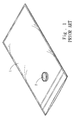
- a conventional sealed zipper bag 1 has an air valve 2 bonded thereon and can be sealed after food has been filled inside, then superfluous air can be sucked out through an air suction member (not shown in the drawing) via the air valve 2 to make the interior of the zipper bag 1 in a vacuum state to prevent oxidization or damping of the food to increase food preservation period.
- the zipper bag 1 can also receive injection of inertia fresh-keeping gas such as nitrogen via a gas injection member (not shown in the drawing) through the air valve 2 to reduce food rotten speed and help to maintain freshness of the food.
- inertia fresh-keeping gas such as nitrogen
- the air valve 2 can be selected a two-way valve to meet air suction or injection requirement, or an one-way air valve, and is bonded to the zipper bag 1 in a selected direction to improve air suction or injection efficiency, and also enhance air-tightness to fully meet use requirements.
- the primary object of the present invention is to provide a detachable pouch air valve and a structure adopted for use on a sealed pouch and a method of use so that the pouch air valve can be repeatedly used.
- the pouch air valve according to the invention includes a hollow tube, an air valve, a first suction plate and a second suction plate.
- the hollow tube has a central passage running through two sides thereof.
- the air valve fills and seals the central passage.
- the first suction plate and second suction plate respectively encircle the outer wall of the hollow tube and suck each other.
- Use of the pouch air valve includes the steps as follow: first, prepare a pliable sealed pouch and form on the sealed pouch an aperture smaller than suction areas of the first and second suction plates; next, have the hollow tube running through the aperture with the first and second suction plates positioned at two sides of the sealed pouch to allow the first and second suction plates respectively sucking the sealed pouch to couple each other and form an installation structure on the sealed pouch.
- the pouch air valve can be fastened to the sealed pouch through the first and second suction plates respectively sucking the sealed pouch to couple each other.
- the coupling of the first and second suction plates also provides desired air-tightness.
- the pouch air valve also provides air deterring effect, it can suck air from the sealed pouch or inject gas into it.
- FIG. 1 is a schematic view of a conventional zipper bag equipped with an air valve.
- FIG. 2 is a schematic view of the pouch air valve of the invention.
- FIG. 3 is an exploded view of the pouch air valve of the invention.
- FIG. 4 is a sectional view of the pouch air valve of the invention.
- FIGS. 5A through 5E are schematic views of the invention in installation and use conditions.
- FIG. 6 is a sectional view of another embodiment of the pouch air valve of the invention.
- FIGS. 7A and 7B are schematic views of another embodiment of the pouch air valve of the invention in use conditions.
- the present invention aims to provide a pouch air valve which includes a hollow tube 10 , an air valve 20 , a first suction plate 30 and a second suction plate 40 .
- the hollow tube 10 has a central passage 11 running through two sides thereof.
- the air valve 20 fills and seals the central passage 11 .
- the first suction plate 30 and second suction plate 40 encircle the outer wall of the hollow tube 10 and suck each other.
- the first suction plate 30 and the hollow tube 10 can be integrally formed to increase air-tightness.
- the outer wall of the hollow tube 10 is formed a latch flange 12 to latch the second suction plate 40 to couple the first suction plate 30 .
- the first and second suction plates 30 and 40 have respectively a groove 31 and 41 at one edge to increase the strength thereof without warping.
- the first suction plate 30 also may have a plurality of bulged spots 32 formed on one side remote from the hollow tube 10 , and another latch flange 13 on a lateral side.
- the air valve 20 can be a one-way valve to increase vacuuming or gas filling efficiency.
- the valve 20 includes a ventilation duct 21 with an inner wall gradually shrunk to form an ellipsoidal closed end 22 and an outer wall gradually shrunk to form a duck-beak pointed end 23 .
- the ellipsoidal closed end 22 has a slit 24 extended to the front end of the duck-beak pointed end 23 .
- the geometrical shapes of the duck-beak pointed end 23 and ellipsoidal closed end 22 naturally form a compression force.
- the ventilation duct 21 does not have a positive pressure inside, the slot 24 is tightly closed to form the one-way air valve.
- FIGS. 5A through 5E for the pouch air valve set forth above in use conditions with the steps discussed as follow:
- the sealed pouch 50 can be any sealable pouch, preferably a zipper bag with the aperture 51 formed by a punch means or formed at the same time when the sealed pouch 50 is fabricated.
- the hollow tube 10 run through the aperture 51 .
- the first suction plate 30 and the hollow tube 10 are formed integrally, and the latch flange 12 is formed on the outer wall of the hollow tube 10
- the sealed pouch 50 can still maintain desired air-tightness even in a warped condition to meet use requirements.
- food 80 A can be placed into the sealed pouch 50 and the sealed pouch 50 can be closed; and an air suction member 60 is provided to cover the central passage 11 of the hollow tube 10 (referring to FIG. 5D ) to suck air from the sealed pouch 50 for vacuuming (discharge the air, referring to FIG. 5E ).
- the other latch flange 13 on the lateral side of the hollow tube 10 can latch the air suction member 60 to improve usability.
- the bulged spots 32 can prevent the food 80 A or sealed pouch 50 from fully in contact with the first suction plate 30 that might hinder air suction process.
- the air inside the sealed pouch 50 can also be expelled by a pressure difference generated by direct squeezing of the sealed pouch 50 .
- FIGS. 7A and 7B Please refer to FIGS. 7A and 7B for another embodiment of the invention.
- the hollow tube 10 is installed on the sealed pouch 50 in a reverse direction (from outer side towards inner side) on the aperture 51 , then install the second suction plate 40 (as shown in FIG. 6 ).
- a gas injection member 70 can be inserted into the air valve 20 (referring to FIG. 7A ) to inject gas into the sealed pouch 50 and fill the sealed pouch 50 with fresh-keeping gas, such as nitrogen (referring to FIG. 7B ).
- the invention provides the first and second suction plates 30 and 40 that are detachably fastened to the hollow tube 10 to be spaced from the seal pouch 50 and form mutual coupling. Not only it can be repeatedly used on different types of seal pouches 50 , the mutual coupling also provides desired air-tightness. Hence the pouch air valve can be repeatedly used to alleviate environmental concerns, and fabrication cost also can be reduced to meet use requirements.
Landscapes
- Engineering & Computer Science (AREA)
- Mechanical Engineering (AREA)
- Chemical & Material Sciences (AREA)
- Dispersion Chemistry (AREA)
- Packages (AREA)
- Vacuum Packaging (AREA)
- Check Valves (AREA)
Abstract
Description
Claims (13)
Applications Claiming Priority (3)
| Application Number | Priority Date | Filing Date | Title |
|---|---|---|---|
| TW100122583A | 2011-06-28 | ||
| TW100122583 | 2011-06-28 | ||
| TW100122583A TW201300292A (en) | 2011-06-28 | 2011-06-28 | Detachable bag gas valve and usage method thereof |
Publications (2)
| Publication Number | Publication Date |
|---|---|
| US20130000755A1 US20130000755A1 (en) | 2013-01-03 |
| US8720468B2 true US8720468B2 (en) | 2014-05-13 |
Family
ID=47389361
Family Applications (1)
| Application Number | Title | Priority Date | Filing Date |
|---|---|---|---|
| US13/219,992 Active 2032-04-23 US8720468B2 (en) | 2011-06-28 | 2011-08-29 | Pouch air valve and structure adopted on a sealed pouch and method of use |
Country Status (2)
| Country | Link |
|---|---|
| US (1) | US8720468B2 (en) |
| TW (1) | TW201300292A (en) |
Cited By (2)
| Publication number | Priority date | Publication date | Assignee | Title |
|---|---|---|---|---|
| US20150013788A1 (en) * | 2013-07-10 | 2015-01-15 | Wei Ling CHEN | Pouch air valve used on sealing pouches |
| US20160264272A1 (en) * | 2015-03-09 | 2016-09-15 | Gary Dean Growden | Method of reusing modified atmospheric packaging |
Families Citing this family (3)
| Publication number | Priority date | Publication date | Assignee | Title |
|---|---|---|---|---|
| WO2014000146A1 (en) * | 2012-06-25 | 2014-01-03 | 倍恩加企业有限公司 | Airtight cover |
| TWM459189U (en) * | 2013-03-29 | 2013-08-11 | Rui-De Wang | Improved device of airtight can |
| WO2014205731A1 (en) * | 2013-06-27 | 2014-12-31 | Chen wei ling | Air valve for bag applied on seal bag |
Citations (2)
| Publication number | Priority date | Publication date | Assignee | Title |
|---|---|---|---|---|
| US1702974A (en) * | 1928-05-12 | 1929-02-19 | Spalding & Bros Ag | Collapsible valve and method of making same |
| US8066433B2 (en) * | 2008-03-14 | 2011-11-29 | Pro-Mart Industries, Inc. | Valve for vacuum storage bag |
Family Cites Families (1)
| Publication number | Priority date | Publication date | Assignee | Title |
|---|---|---|---|---|
| JP4548791B2 (en) * | 2006-04-14 | 2010-09-22 | 月島機械株式会社 | centrifuge |
-
2011
- 2011-06-28 TW TW100122583A patent/TW201300292A/en unknown
- 2011-08-29 US US13/219,992 patent/US8720468B2/en active Active
Patent Citations (2)
| Publication number | Priority date | Publication date | Assignee | Title |
|---|---|---|---|---|
| US1702974A (en) * | 1928-05-12 | 1929-02-19 | Spalding & Bros Ag | Collapsible valve and method of making same |
| US8066433B2 (en) * | 2008-03-14 | 2011-11-29 | Pro-Mart Industries, Inc. | Valve for vacuum storage bag |
Cited By (3)
| Publication number | Priority date | Publication date | Assignee | Title |
|---|---|---|---|---|
| US20150013788A1 (en) * | 2013-07-10 | 2015-01-15 | Wei Ling CHEN | Pouch air valve used on sealing pouches |
| US8936044B1 (en) * | 2013-07-10 | 2015-01-20 | Wei Ling CHEN | Pouch air valve used on sealing pouches |
| US20160264272A1 (en) * | 2015-03-09 | 2016-09-15 | Gary Dean Growden | Method of reusing modified atmospheric packaging |
Also Published As
| Publication number | Publication date |
|---|---|
| US20130000755A1 (en) | 2013-01-03 |
| TW201300292A (en) | 2013-01-01 |
| TWI419817B (en) | 2013-12-21 |
Similar Documents
| Publication | Publication Date | Title |
|---|---|---|
| KR101616655B1 (en) | Detachable air valve for bag and use method thereof | |
| US20130000755A1 (en) | Pouch air valve and structure adopted on a sealed pouch and method of use | |
| US6581641B2 (en) | One-way valve for use with vacuum pump | |
| KR101571339B1 (en) | One-way valve with flapper for vacuum bag | |
| EP0644128B1 (en) | Combination of a sealable can adapted to be evacuated and a vacuum pump | |
| US8936044B1 (en) | Pouch air valve used on sealing pouches | |
| US20120099806A1 (en) | Vacuum compression storage bags | |
| US20090007803A1 (en) | Device and Method for Evacuating a Storage Bag | |
| CN209567324U (en) | A kind of packing box that can be vacuumized from bottom | |
| US20140076894A1 (en) | Airtight cover | |
| CN214930952U (en) | Vacuum packaging device structure with vacuum-proof grain and plane sealing bag | |
| KR101876324B1 (en) | Vacuum desiccator | |
| CN208107243U (en) | One-way exhaust valve | |
| CN213293275U (en) | High-barrier transparent freshness protection package | |
| US20150198413A1 (en) | Evacuable Firearm Enclosure | |
| KR101812795B1 (en) | Intake valve for compression pack | |
| JP2007153436A (en) | Vacuum packaging apparatus | |
| KR101473849B1 (en) | Vaccum chamber having vaccum generating apparatus | |
| KR100606601B1 (en) | Zipper Bag Vacuum | |
| JP6008283B2 (en) | Thermal insulation building material | |
| CN203211679U (en) | Airtight bag with sealing structure | |
| TWM631810U (en) | Moisture-proof urn | |
| KR20120075894A (en) | Vinyl bag with inner check valve | |
| KR101962244B1 (en) | Intake valve for compression pack | |
| CN209236726U (en) | Improved structure of vacuum urn |
Legal Events
| Date | Code | Title | Description |
|---|---|---|---|
| STCF | Information on status: patent grant |
Free format text: PATENTED CASE |
|
| MAFP | Maintenance fee payment |
Free format text: PAYMENT OF MAINTENANCE FEE, 4TH YR, SMALL ENTITY (ORIGINAL EVENT CODE: M2551) Year of fee payment: 4 |
|
| AS | Assignment |
Owner name: IDEARITE HOLDINGS PTE. LTD., SINGAPORE Free format text: ASSIGNMENT OF ASSIGNORS INTEREST;ASSIGNOR:CHEN, WEI-LING;REEL/FRAME:055496/0135 Effective date: 20210223 |
|
| MAFP | Maintenance fee payment |
Free format text: PAYMENT OF MAINTENANCE FEE, 8TH YR, SMALL ENTITY (ORIGINAL EVENT CODE: M2552); ENTITY STATUS OF PATENT OWNER: SMALL ENTITY Year of fee payment: 8 |
|
| MAFP | Maintenance fee payment |
Free format text: PAYMENT OF MAINTENANCE FEE, 12TH YR, SMALL ENTITY (ORIGINAL EVENT CODE: M2553); ENTITY STATUS OF PATENT OWNER: SMALL ENTITY Year of fee payment: 12 |