US8720316B2 - High-pressure fuel pump - Google Patents
High-pressure fuel pump Download PDFInfo
- Publication number
- US8720316B2 US8720316B2 US13/045,669 US201113045669A US8720316B2 US 8720316 B2 US8720316 B2 US 8720316B2 US 201113045669 A US201113045669 A US 201113045669A US 8720316 B2 US8720316 B2 US 8720316B2
- Authority
- US
- United States
- Prior art keywords
- housing
- magnet
- pump
- swash plate
- drive shaft
- Prior art date
- Legal status (The legal status is an assumption and is not a legal conclusion. Google has not performed a legal analysis and makes no representation as to the accuracy of the status listed.)
- Expired - Fee Related, expires
Links
Images


Classifications
-
- F—MECHANICAL ENGINEERING; LIGHTING; HEATING; WEAPONS; BLASTING
- F04—POSITIVE - DISPLACEMENT MACHINES FOR LIQUIDS; PUMPS FOR LIQUIDS OR ELASTIC FLUIDS
- F04B—POSITIVE-DISPLACEMENT MACHINES FOR LIQUIDS; PUMPS
- F04B1/00—Multi-cylinder machines or pumps characterised by number or arrangement of cylinders
- F04B1/12—Multi-cylinder machines or pumps characterised by number or arrangement of cylinders having cylinder axes coaxial with, or parallel or inclined to, main shaft axis
- F04B1/20—Multi-cylinder machines or pumps characterised by number or arrangement of cylinders having cylinder axes coaxial with, or parallel or inclined to, main shaft axis having rotary cylinder block
- F04B1/2014—Details or component parts
- F04B1/2078—Swash plates
-
- F—MECHANICAL ENGINEERING; LIGHTING; HEATING; WEAPONS; BLASTING
- F04—POSITIVE - DISPLACEMENT MACHINES FOR LIQUIDS; PUMPS FOR LIQUIDS OR ELASTIC FLUIDS
- F04B—POSITIVE-DISPLACEMENT MACHINES FOR LIQUIDS; PUMPS
- F04B1/00—Multi-cylinder machines or pumps characterised by number or arrangement of cylinders
- F04B1/12—Multi-cylinder machines or pumps characterised by number or arrangement of cylinders having cylinder axes coaxial with, or parallel or inclined to, main shaft axis
- F04B1/14—Multi-cylinder machines or pumps characterised by number or arrangement of cylinders having cylinder axes coaxial with, or parallel or inclined to, main shaft axis having stationary cylinders
- F04B1/141—Details or component parts
- F04B1/146—Swash plates; Actuating elements
-
- F—MECHANICAL ENGINEERING; LIGHTING; HEATING; WEAPONS; BLASTING
- F04—POSITIVE - DISPLACEMENT MACHINES FOR LIQUIDS; PUMPS FOR LIQUIDS OR ELASTIC FLUIDS
- F04B—POSITIVE-DISPLACEMENT MACHINES FOR LIQUIDS; PUMPS
- F04B39/00—Component parts, details, or accessories, of pumps or pumping systems specially adapted for elastic fluids, not otherwise provided for in, or of interest apart from, groups F04B25/00 - F04B37/00
- F04B39/16—Filtration; Moisture separation
-
- F—MECHANICAL ENGINEERING; LIGHTING; HEATING; WEAPONS; BLASTING
- F04—POSITIVE - DISPLACEMENT MACHINES FOR LIQUIDS; PUMPS FOR LIQUIDS OR ELASTIC FLUIDS
- F04B—POSITIVE-DISPLACEMENT MACHINES FOR LIQUIDS; PUMPS
- F04B53/00—Component parts, details or accessories not provided for in, or of interest apart from, groups F04B1/00 - F04B23/00 or F04B39/00 - F04B47/00
- F04B53/18—Lubricating
-
- F—MECHANICAL ENGINEERING; LIGHTING; HEATING; WEAPONS; BLASTING
- F04—POSITIVE - DISPLACEMENT MACHINES FOR LIQUIDS; PUMPS FOR LIQUIDS OR ELASTIC FLUIDS
- F04B—POSITIVE-DISPLACEMENT MACHINES FOR LIQUIDS; PUMPS
- F04B53/00—Component parts, details or accessories not provided for in, or of interest apart from, groups F04B1/00 - F04B23/00 or F04B39/00 - F04B47/00
- F04B53/20—Filtering
-
- F—MECHANICAL ENGINEERING; LIGHTING; HEATING; WEAPONS; BLASTING
- F04—POSITIVE - DISPLACEMENT MACHINES FOR LIQUIDS; PUMPS FOR LIQUIDS OR ELASTIC FLUIDS
- F04C—ROTARY-PISTON, OR OSCILLATING-PISTON, POSITIVE-DISPLACEMENT MACHINES FOR LIQUIDS; ROTARY-PISTON, OR OSCILLATING-PISTON, POSITIVE-DISPLACEMENT PUMPS
- F04C13/00—Adaptations of machines or pumps for special use, e.g. for extremely high pressures
- F04C13/005—Removing contaminants, deposits or scale from the pump; Cleaning
-
- F—MECHANICAL ENGINEERING; LIGHTING; HEATING; WEAPONS; BLASTING
- F04—POSITIVE - DISPLACEMENT MACHINES FOR LIQUIDS; PUMPS FOR LIQUIDS OR ELASTIC FLUIDS
- F04C—ROTARY-PISTON, OR OSCILLATING-PISTON, POSITIVE-DISPLACEMENT MACHINES FOR LIQUIDS; ROTARY-PISTON, OR OSCILLATING-PISTON, POSITIVE-DISPLACEMENT PUMPS
- F04C2210/00—Fluid
- F04C2210/60—Condition
- F04C2210/62—Purity
Definitions
- the invention relates to a high-pressure fuel pump.
- the invention relates to a high-pressure fuel pump with a housing and a swash plate which is mounted in the housing and is arranged in an oil space of the housing, and with a drive shaft which is connected to the swash plate and passes through a housing opening, and with a seal for the drive shaft, which seal is mounted in the housing in the region of the housing opening, wherein the high-pressure fuel pump has a plurality of pump elements for sucking up, compressing and ejecting fuel, which pump elements can be acted upon consecutively by means of the rotating swash plate.
- Pump arrangements having a low-pressure pump and a high-pressure pump are used in motor vehicles, in particular passenger vehicles.
- the low-pressure fuel pump is arranged in the fuel tank and conveys fuel to a high-pressure fuel pump which supplies fuel at a pressure of generally greater than 100 bar to combustion spaces of an internal combustion engine.
- Said high-pressure fuel pump is generally connected to a cylinder head of the internal combustion engine and is driven by means of the camshaft of the internal combustion engine.
- said high-pressure fuel pump has components which are subject to wear.
- abrasion of metallic, iron-containing particles of bearing elements of the swash plate and other optionally used elements, such as springs and sliding blocks can be noted during the operation designed for the lifetime of the high-pressure fuel pump.
- an increasing and therefore cumulative accumulation of iron-containing particles arises.
- the particles pass, for example, into the bearings, and therefore the wear thereof is increased, and continue into the region of the seal for the drive shaft, thus increasing the risk of a loss of oil. This may lead to the pump no longer functioning, and therefore the calculated lifetime of the high-pressure fuel pump is not reached.
- DE 39 07 317 A1 which is incorporated by reference herein, describes a fuel tank, on the bottom of which a plurality of magnets are provided. As an alternative, a plurality of magnets are provided within the fuel filter.
- An object of the present invention is to provide a high-pressure fuel pump which, by means of reduction of premature wear, in particular premature wear of the seal and/or of the bearings, has a long lifetime.
- the object is achieved in a high-pressure fuel pump of the type mentioned at the beginning in that the high-pressure fuel pump has at least one magnet, the magnetic force field of which acts on the oil space of the housing.
- At least one magnet interacts with the high-pressure fuel pump.
- Said magnet is attached to the high-pressure fuel pump at a suitable location, said location being selected such that the magnetic force field of the magnet can act on the oil space of the housing.
- the magnetic force field of the respective magnet acts on a dirt collecting pocket which is assigned thereto and is on the oil space side, and therefore, as the oil flows in the oil space, metallic, iron-containing dirt particles are conducted under the action of the oil-side force field of the magnet into the dirt collecting pocket and are permanently retained there under the action of the magnet.
- the iron-containing dirt particles are therefore deflected under the action of the magnetic force field out of the main stream of oil being conveyed and accumulate in the region of the magnet.
- the magnet and, in particular, the dirt collecting pocket should be arranged at a distance from the seal, in particular in a region of the oil space remote from the seal.
- the distance should be selected at least in such a manner that the dirt particles are not conveyed into the region of the seal but rather the magnet causes the dirt particles to be conveyed away from the seal. It is therefore an aim to avoid dirt particles on the seal or on the bearings, in particular on a sealing lip of a shaft sealing ring.
- the dirt particles formed in the oil space are concentrated by the magnet in the dirt collecting pocket.
- the at least one magnet can be placed in the interior of the high-pressure fuel pump and/or can be placed on the exterior surface of the high-pressure fuel pump.
- said magnet is preferably connected on the oil space side of the housing to the housing and/or to the drive shaft and/or to the swash plate.
- the mounting of the magnet can turn out to be particularly simple if the housing and/or the drive shaft and/or the swash plate have/has a receiving space, which is open to the oil space, for the magnet.
- the magnet can simply be inserted, in particular clamped, into said open receptacle. Of course, other types of fastening are possible.
- the housing receives the magnet, it is considered to be particularly advantageous if the radial interior surface of the housing receives the magnet.
- the housing therefore receives the magnet in the region of the radially outer contour of the oil space, at a point where, in particular under the action of centrifugal forces which act on the oil, it can be assumed that the dirt particles will preferably accumulate because of the relatively high specific weight.
- the magnet is received by the drive shaft and/or the swash plate in the region of the axis of rotation thereof.
- the magnet is therefore arranged at a location at which only small centrifugal forces, if any at all, act on the magnet and also on the dirt particles held by the latter.
- the at least one magnet can be connected to the housing on that side thereof which is remote from the oil space, therefore on the exterior surface of the housing.
- the magnet is indeed not assigned directly to the oil but rather the magnet acts on the oil space through the housing. Nevertheless, if the magnet is dimensioned to be sufficiently powerful, the same effect can be obtained as when the magnet is arranged on the interior surface of the housing.
- the arrangement of the magnet on the exterior surface of the housing makes it possible in a particularly simple manner to attach the magnet or to retrospectively equip the high-pressure fuel pump with the magnet. All that is required for this purpose is to attach the magnet to the outside of the housing or to design or remodel the housing with an outwardly open receptacle for the magnet.
- the desired dirt catching effect can be achieved in a particularly simple manner at minimum cost if the respective magnet is a permanent magnet.
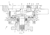
- FIG. 1 shows a section through the high-pressure fuel pump, illustrated for the region of a housing, a swash plate and a shaft of the high-pressure fuel pump to which a magnet is assigned,
- FIGS. 2 through 4 show sectional illustrations according to FIG. 1 for a modified arrangement of the magnet.
- FIGS. 1 and 3 show a high-pressure fuel pump 1 in that region which receives the driving elements for pump elements, wherein said pump elements serve to suck up, compress and eject fuel. That region of the high-pressure fuel pump through which fuel does not flow is therefore illustrated.
- a housing 2 a swash plate 4 which is mounted in the housing 2 and is arranged in an oil space 3 of the housing 2 , and a drive shaft 5 which is connected to the swash plate 4 are shown.
- Said drive shaft passes through a housing opening 6 , wherein a seal 7 which is designed as a shaft sealing ring 8 with a sealing lip 9 , the latter bearing against the drive shaft 5 , is mounted in the housing 2 in the region of said housing opening 6 .
- That end of the drive shaft 5 which is arranged outside the housing 2 has a splined shaft section 10 onto which a coupling element 11 , which is fixed axially, is fitted, the coupling element 11 engaging in a camshaft (not illustrated) of an internal combustion engine.
- the housing pump 1 is connected to a cylinder head of the internal combustion engine, and in particular is flange-mounted on the cylinder head in a manner not shown.
- the reference number 12 denotes the axis of rotation of the drive shaft 5 and swash plate 4 .
- Said swash plate is mounted in the housing 2 via a radial bearing 13 and via an axial bearing 14 , which are each designed as needle bearings.
- Two of three pump elements 15 of the high-pressure fuel pump are illustrated, the pump pistons 16 of which are acted upon consecutively by means of the swash plate 4 rotating about the axis 12 , with the consequence that fuel is sucked up, compressed and ejected in a manner not illustrated specifically, for the purpose of feeding the fuel to the internal combustion engine.
- That surface 17 of the swash plate 4 which is inclined with respect to the perpendicular to the axis of rotation 12 makes contact with the pump pistons 16 , with the respective pump piston 16 being pressed against the surface 17 of the swash plate 4 under the action of a spring 18 .
- the oil space 3 is filled with hydraulic oil, specifically in the form of a lifetime filling, and therefore the hydraulic oil remains in the oil space 3 throughout the entire lifetime of the high-pressure fuel pump 1 .
- wear of the individual components in the illustrated region of interest of the high-pressure fuel pump can be noted, with the consequence of abrasion of dirt particles, in particular in the region of the radial bearing 13 and of the axial bearing 14 with the needles and bearing springs arranged there, and also in the region of sliding blocks 19 which serve for the actual contact connection of a spherical-head-shaped end of the pump pistons 19 with the swash plate 4 .
- the embodiment according to FIG. 1 makes provision for the interior surface of the housing 2 , the side therefore which is directly adjacent to the oil space 3 , to have a recess 20 which is open toward the oil space 3 and into which a relatively short, bar-shaped magnet 21 , which is in the form of a permanent magnet, is inserted in a clamping manner.
- Said magnet is arranged radially on the outside at a location where, because of the design of the high-pressure fuel pump 1 , dirt particles in particular collect.
- the magnet 21 is arranged set back somewhat and is therefore arranged radially further on the outside, thus forming a dirt collecting pocket 22 in the housing 2 somewhat further radially on the inside.
- Said dirt collecting pocket 22 forms a reservoir for dirt particles which are accordingly collected locally and are not only attracted by the magnet 21 but also, upon positioning in the dirt collecting pocket 22 , are kept permanently in the latter.
- the magnet 21 can draw the dirt particles into the region of the dirt collecting pocket 22 because the magnetic force field of said magnet acts on the oil space 3 of the housing 2 , at least in that region of the oil space 3 which is adjacent to the dirt collecting pocket 22 . Dirt particles which are conveyed continuously through the oil space 3 are therefore is conveyed away into the dirt collecting pocket 22 when said dirt particles enter the force field of the magnet. This effectively avoids the dirt particles entering the region of the seal 7 or of the bearings 13 and 14 .
- FIG. 2 shows a modification of the illustrated region of the high-pressure fuel pump 1 to the effect that the magnet 21 is not mounted in the housing 2 but rather in the drive shaft 5 concentrically with respect to the axis of rotation 12 , in the region of that end of the drive shaft 5 which faces the swash plate 4 .
- the drive shaft 5 is provided there with a corresponding recess 20 which serves to receive the magnet 21 which is inserted into the latter under prestress. Dirt particles which are conveyed in the region of this end of the drive shaft 5 and of that region of the swash plate 4 which is assigned to the drive shaft 5 are therefore drawn onto the magnet 21 by means of the latter and collected there.
- FIG. 3 differs from that according to FIGS. 1 and 2 in that the magnet 21 is now mounted in the region of the housing 2 , in particular in a housing cover through which the pump pistons 16 pass.
- the magnet 21 may absolutely also be arranged at different locations in the housing 2 , in particular on the exterior surface of the housing 2 , and therefore the magnet 1 does not come into contact with the hydraulic oil found in the oil space 3 .
- a simple modification of the embodiment according to FIG. 1 makes provision for a bore to be inserted into the housing 2 from the outside, the bore therefore forming the recess 20 into which the magnet 21 is inserted.
- a dirt collecting pocket 22 facing the oil space 3 , to be provided, as illustrated for the embodiment according to FIG. 1 .
- the magnet 21 should be arranged in such a manner that the action of the magnetic force field thereof extends into the oil space 3 .
- embodiment according to FIG. 1 The magnet 21 should be arranged in such a manner that the action of the magnetic force field thereof extends into the oil space 3 .
Landscapes
- Engineering & Computer Science (AREA)
- Mechanical Engineering (AREA)
- General Engineering & Computer Science (AREA)
- Details Of Reciprocating Pumps (AREA)
- Reciprocating Pumps (AREA)
Abstract
Description
- 1 high-pressure fuel pump
- 2 housing
- 3 oil space
- 4 swash plate
- 5 drive shaft
- 6 housing opening
- 7 seal
- 8 shaft sealing ring
- 9 sealing lip
- 10 splined shaft section
- 11 coupling element
- 12 axis of rotation
- 13 radial bearing
- 14 axial bearing
- 15 pump element
- 16 pump piston
- 17 surface
- 18 spring
- 19 sliding block
- 20 recess
- 21 magnet
- 22 dirt collecting pocket
Claims (9)
Applications Claiming Priority (3)
| Application Number | Priority Date | Filing Date | Title |
|---|---|---|---|
| DE102010011292A DE102010011292A1 (en) | 2010-03-13 | 2010-03-13 | High-pressure fuel pump |
| DE102010011292.5 | 2010-03-13 | ||
| DE102010011292 | 2010-03-13 |
Publications (2)
| Publication Number | Publication Date |
|---|---|
| US20110219947A1 US20110219947A1 (en) | 2011-09-15 |
| US8720316B2 true US8720316B2 (en) | 2014-05-13 |
Family
ID=43857748
Family Applications (1)
| Application Number | Title | Priority Date | Filing Date |
|---|---|---|---|
| US13/045,669 Expired - Fee Related US8720316B2 (en) | 2010-03-13 | 2011-03-11 | High-pressure fuel pump |
Country Status (4)
| Country | Link |
|---|---|
| US (1) | US8720316B2 (en) |
| EP (1) | EP2369180B1 (en) |
| CN (1) | CN102192061A (en) |
| DE (1) | DE102010011292A1 (en) |
Families Citing this family (5)
| Publication number | Priority date | Publication date | Assignee | Title |
|---|---|---|---|---|
| DE102011053358A1 (en) * | 2011-09-07 | 2013-03-07 | Dr. Ing. H.C. F. Porsche Aktiengesellschaft | Fuel pump, particularly single piston high-pressure fuel pump for internal combustion engines of passenger cars, has housing, piston mounted in housing and arranged in oil space of housing and drive shaft mounted in housing |
| DE102011088949C5 (en) * | 2011-12-19 | 2022-02-24 | Vitesco Technologies GmbH | level sensor |
| DE102012200054A1 (en) | 2012-01-03 | 2013-07-04 | Continental Automotive Gmbh | Valve device for a motor vehicle |
| CN103147962B (en) * | 2013-03-13 | 2015-09-02 | 肖立峰 | By the shaft-driven diaphragm pump of conical pendu0 dynamicthrust |
| CN119373738B (en) * | 2024-10-25 | 2026-04-10 | 杰锋汽车动力系统股份有限公司 | Impurity collecting and storing structure of hydrogen circulating pump |
Citations (13)
| Publication number | Priority date | Publication date | Assignee | Title |
|---|---|---|---|---|
| DE1051063B (en) | 1956-01-27 | 1959-02-19 | Farymann Diesel | Lubrication of the engine in internal combustion engines |
| DE1937072A1 (en) | 1968-07-25 | 1970-01-29 | Gratzmuller Jean Louis | Single cylinder eccentric pump |
| DE2603230A1 (en) | 1976-01-29 | 1977-08-04 | Licentia Gmbh | Dirt particle separator for small refrigerator compressors - is permanent magnet fitted into refrigerant and lubricant flow path |
| EP0149219A2 (en) | 1983-12-28 | 1985-07-24 | Speck-Kolbenpumpen-Fabrik | Piston pump |
| US4627793A (en) | 1984-06-13 | 1986-12-09 | Nippondenso Co., Ltd. | Motor-driven radial plunger pump |
| US4652215A (en) | 1984-04-12 | 1987-03-24 | Nippondenso Co., Ltd. | Variable capacity radial piston pump |
| DE3907317A1 (en) | 1988-03-09 | 1989-09-21 | Mitsubishi Electric Corp | WELDED TANKS AND METHOD FOR CLEANING THEM |
| DE19709781A1 (en) | 1997-03-10 | 1998-09-17 | Bosch Gmbh Robert | Automotive fuel filter |
| US6142060A (en) | 1997-05-19 | 2000-11-07 | Honda Giken Kogyo Kabushiki Kaisha | High pressure fuel pump having a bellows sealing arrangement |
| DE10039169A1 (en) | 1999-08-12 | 2001-03-15 | Hitachi Ltd | Fuel pump has a surface hardening layer containing either a nitrided layer, a carburized layer and quenched layer or a carbonitrided layer, and a metal compound layer formed on the surface hardening layer |
| DE10327408A1 (en) | 2002-10-19 | 2004-04-29 | Robert Bosch Gmbh | Device for damping pressure pulsations in a fluid system, in particular in a fuel system of an internal combustion engine |
| WO2007061385A1 (en) | 2005-11-25 | 2007-05-31 | Matsushita Electric Industrial Co., Ltd. | Magnetic trap for ferrous contaminants in lubricant |
| US7320576B2 (en) * | 2002-08-27 | 2008-01-22 | Sanden Corporation | Clutchless variable displacement refrigerant compressor with mechanism for reducing displacement work at increased driven speed during non-operation of refrigerating system including the compressor |
-
2010
- 2010-03-13 DE DE102010011292A patent/DE102010011292A1/en not_active Withdrawn
- 2010-12-24 EP EP10016081.1A patent/EP2369180B1/en not_active Not-in-force
-
2011
- 2011-03-11 US US13/045,669 patent/US8720316B2/en not_active Expired - Fee Related
- 2011-03-11 CN CN2011100629429A patent/CN102192061A/en active Pending
Patent Citations (18)
| Publication number | Priority date | Publication date | Assignee | Title |
|---|---|---|---|---|
| DE1051063B (en) | 1956-01-27 | 1959-02-19 | Farymann Diesel | Lubrication of the engine in internal combustion engines |
| DE1937072A1 (en) | 1968-07-25 | 1970-01-29 | Gratzmuller Jean Louis | Single cylinder eccentric pump |
| US3597119A (en) | 1968-07-25 | 1971-08-03 | Jean Louis Gratzmuller | Single-cylinder eccentric actuated pump |
| DE2603230A1 (en) | 1976-01-29 | 1977-08-04 | Licentia Gmbh | Dirt particle separator for small refrigerator compressors - is permanent magnet fitted into refrigerant and lubricant flow path |
| EP0149219A2 (en) | 1983-12-28 | 1985-07-24 | Speck-Kolbenpumpen-Fabrik | Piston pump |
| US4583921A (en) * | 1983-12-28 | 1986-04-22 | Speck-Kolbenpumpen-Fabrik Otto Speck Kg | Plunger pump |
| US4652215A (en) | 1984-04-12 | 1987-03-24 | Nippondenso Co., Ltd. | Variable capacity radial piston pump |
| US4627793A (en) | 1984-06-13 | 1986-12-09 | Nippondenso Co., Ltd. | Motor-driven radial plunger pump |
| DE3907317A1 (en) | 1988-03-09 | 1989-09-21 | Mitsubishi Electric Corp | WELDED TANKS AND METHOD FOR CLEANING THEM |
| US5273193A (en) | 1988-03-09 | 1993-12-28 | Mitsubishi Denki Kabushiki Kaisha | Welded fuel tank having a magnet for collecting weld spatter and method for collecting weld spatter |
| DE19709781A1 (en) | 1997-03-10 | 1998-09-17 | Bosch Gmbh Robert | Automotive fuel filter |
| US6142060A (en) | 1997-05-19 | 2000-11-07 | Honda Giken Kogyo Kabushiki Kaisha | High pressure fuel pump having a bellows sealing arrangement |
| DE69822698T2 (en) | 1997-05-19 | 2005-02-10 | Honda Giken Kogyo K.K. | High-pressure fuel pump |
| DE10039169A1 (en) | 1999-08-12 | 2001-03-15 | Hitachi Ltd | Fuel pump has a surface hardening layer containing either a nitrided layer, a carburized layer and quenched layer or a carbonitrided layer, and a metal compound layer formed on the surface hardening layer |
| US6543424B1 (en) | 1999-08-12 | 2003-04-08 | Hitachi, Ltd. | Fuel pump, in-cylinder direct injection type internal combustion engine using the same and surface treatment method |
| US7320576B2 (en) * | 2002-08-27 | 2008-01-22 | Sanden Corporation | Clutchless variable displacement refrigerant compressor with mechanism for reducing displacement work at increased driven speed during non-operation of refrigerating system including the compressor |
| DE10327408A1 (en) | 2002-10-19 | 2004-04-29 | Robert Bosch Gmbh | Device for damping pressure pulsations in a fluid system, in particular in a fuel system of an internal combustion engine |
| WO2007061385A1 (en) | 2005-11-25 | 2007-05-31 | Matsushita Electric Industrial Co., Ltd. | Magnetic trap for ferrous contaminants in lubricant |
Non-Patent Citations (1)
| Title |
|---|
| European Search Report issued in related Application No. EP 10016081.1 on May 19, 2011. |
Also Published As
| Publication number | Publication date |
|---|---|
| DE102010011292A1 (en) | 2011-09-15 |
| CN102192061A (en) | 2011-09-21 |
| EP2369180B1 (en) | 2014-09-17 |
| EP2369180A1 (en) | 2011-09-28 |
| US20110219947A1 (en) | 2011-09-15 |
Similar Documents
| Publication | Publication Date | Title |
|---|---|---|
| US8720316B2 (en) | High-pressure fuel pump | |
| CN102959227B (en) | Pumps, especially high-pressure fuel pumps | |
| KR101045270B1 (en) | Motor rotor and compressor with it | |
| CN104662296B (en) | Reciprocating compressor and method of driving the same | |
| EP2700816A1 (en) | Reciprocating compressor | |
| EP2220370B1 (en) | Reciprocating compressor | |
| ITMI991357A1 (en) | COMPRESSOR FOR COMPRESSION OF A FLUID INCLUDING LUBRICANT OIL | |
| EP0151777A1 (en) | Piston assembly for a refrigerant compressor | |
| CN104160150A (en) | Improved rotary axial piston pump | |
| CN103168189A (en) | Pump seal | |
| US6745667B1 (en) | Motor-pump aggregate | |
| JP2001510531A (en) | Radial piston pump for high pressure fuel supply | |
| EP3597923B1 (en) | Rotary compressor | |
| CN109595251A (en) | Parts of bearings and compressor, refrigerating plant with it | |
| US11015588B2 (en) | Compact air compressor | |
| JP4750377B2 (en) | Reciprocating compressor | |
| KR101428815B1 (en) | Compressor | |
| US20200011312A1 (en) | Cylinder assemble structure for compact air compressor | |
| US12339043B2 (en) | Compressor | |
| EP1162371A1 (en) | Compressor and method of lubricating the compressor | |
| JP5259939B2 (en) | Linear compressor | |
| US7927084B2 (en) | Magnetic trap for ferrous contaminants in lubricant | |
| CN110691904B (en) | High Pressure Fuel Pump Assembly for Internal Combustion Piston Engines | |
| KR20130110069A (en) | Compressor | |
| KR100963987B1 (en) | Swash plate compressor |
Legal Events
| Date | Code | Title | Description |
|---|---|---|---|
| AS | Assignment |
Owner name: DR. ING. H.C. F. PORSCHE AKTIENGESELLSCHAFT, GERMA Free format text: ASSIGNMENT OF ASSIGNORS INTEREST;ASSIGNOR:DEEG, HANS-PETER;REEL/FRAME:025967/0036 Effective date: 20110208 |
|
| FEPP | Fee payment procedure |
Free format text: PAYOR NUMBER ASSIGNED (ORIGINAL EVENT CODE: ASPN); ENTITY STATUS OF PATENT OWNER: LARGE ENTITY |
|
| STCF | Information on status: patent grant |
Free format text: PATENTED CASE |
|
| MAFP | Maintenance fee payment |
Free format text: PAYMENT OF MAINTENANCE FEE, 4TH YEAR, LARGE ENTITY (ORIGINAL EVENT CODE: M1551) Year of fee payment: 4 |
|
| FEPP | Fee payment procedure |
Free format text: MAINTENANCE FEE REMINDER MAILED (ORIGINAL EVENT CODE: REM.); ENTITY STATUS OF PATENT OWNER: LARGE ENTITY |
|
| LAPS | Lapse for failure to pay maintenance fees |
Free format text: PATENT EXPIRED FOR FAILURE TO PAY MAINTENANCE FEES (ORIGINAL EVENT CODE: EXP.); ENTITY STATUS OF PATENT OWNER: LARGE ENTITY |
|
| STCH | Information on status: patent discontinuation |
Free format text: PATENT EXPIRED DUE TO NONPAYMENT OF MAINTENANCE FEES UNDER 37 CFR 1.362 |
|
| FP | Lapsed due to failure to pay maintenance fee |
Effective date: 20220513 |