US8699113B2 - Deformable mirror suspension - Google Patents
Deformable mirror suspension Download PDFInfo
- Publication number
- US8699113B2 US8699113B2 US13/129,563 US200913129563A US8699113B2 US 8699113 B2 US8699113 B2 US 8699113B2 US 200913129563 A US200913129563 A US 200913129563A US 8699113 B2 US8699113 B2 US 8699113B2
- Authority
- US
- United States
- Prior art keywords
- mirror
- mirror assembly
- suspension
- support structure
- serpentine
- Prior art date
- Legal status (The legal status is an assumption and is not a legal conclusion. Google has not performed a legal analysis and makes no representation as to the accuracy of the status listed.)
- Expired - Fee Related, expires
Links
Images


Classifications
-
- G—PHYSICS
- G02—OPTICS
- G02B—OPTICAL ELEMENTS, SYSTEMS OR APPARATUS
- G02B26/00—Optical devices or arrangements for the control of light using movable or deformable optical elements
- G02B26/08—Optical devices or arrangements for the control of light using movable or deformable optical elements for controlling the direction of light
- G02B26/0816—Optical devices or arrangements for the control of light using movable or deformable optical elements for controlling the direction of light by means of one or more reflecting elements
- G02B26/0833—Optical devices or arrangements for the control of light using movable or deformable optical elements for controlling the direction of light by means of one or more reflecting elements the reflecting element being a micromechanical device, e.g. a MEMS mirror, DMD
- G02B26/0858—Optical devices or arrangements for the control of light using movable or deformable optical elements for controlling the direction of light by means of one or more reflecting elements the reflecting element being a micromechanical device, e.g. a MEMS mirror, DMD the reflecting means being moved or deformed by piezoelectric means
Definitions
- This invention relates to a suspension for a deformable mirror, and to a deformable mirror assembly including such suspension. In particular it concerns suspensions for bimorph mirrors.
- Deformable mirrors are often used in the field of adaptive optics. For example, phase distortions in a signal may be sensed by a wavefront sensor and these distortions may be corrected by using a deformable mirror linked to an appropriate control system. Such deformable mirrors may be employed in numerous fields, including:
- Bimorph deformable mirrors have been proposed as low cost adaptive mirrors.
- the two main operation parameters of a bimorph mirror are its bandwidth and its stroke.
- Bandwidth determines how quickly the mirror can be deformed and hence, for example, how quickly the mirror can respond to the variations in atmospheric turbulence.
- Stroke corresponds to the maximum displacement of the mirror when deformed and this determines, for example, the level of turbulence that can be corrected.
- both bandwidth and stroke should be maximised.
- conventional design means that there is a reciprocal relationship between these two parameters, and one parameter can only be improved at the expense of the other. Therefore, to date, designers have always looked for ways to improve either the resonant frequency or the stroke independently from each other.
- a deformable mirror is supported rigidly around its edge, for example an annular ring overlapping the periphery of the mirror is used to hold the mirror firmly in position.
- Such an arrangement benefits from being simple yet rugged.
- it has an inherent disadvantage in that it creates a dead space around the mirror's edge. This corresponds both to the area of the mirror held firmly under the annular ring and also to the adjacent area.
- the useable area of the deformable mirror (the active area) must bend to adopt a desired profile, for example either a concave or a convex shape.
- the annular area between the active area and the annular ring must bend in the opposite sense and so forms an area of inflexion that has undesirable optical properties.
- the active area occupies only a central portion of the whole mirror.
- a deformable mirror assembly comprising a deformable mirror, a support structure, a suspension supporting the mirror from the support structure, and means for deforming the mirror other than by forces applied through the suspension, such that the mirror moves towards and away from the support structure, characterised in that the suspension comprises at least one elongate element, least a portion of which extends transversely and preferably obliquely relative to the direction of said movement and accommodates said movement by bending.
- the at least one element may extend between points on the mirror and on the support structure which are spaced apart laterally of said direction.
- the assembly may comprise a plurality of said elements obliquely inclined in one sense and a further plurality of said elements obliquely inclined in an opposite sense, so as to cross each other, the elements being joined together where they cross.
- the at least one element may be of serpentine shape.
- compliance of the suspension in at least one direction is provided by deformation of the at least one serpentine element in a manner which varies the curvature of the serpentine element.
- the deformation when produced by a tensile load may tend to straighten the at least one serpentine element.
- the at least one serpentine element may have a longitudinal extent in said direction, the serpentine shape of the element extending transversely of said longitudinal extent such that a straight line extending between the ends of the element passes at least partially outside said shape.
- the serpentine shape may be a herringbone or zig-zag shape.
- the serpentine shape includes at least two oppositely-handed bends.
- the at least one suspension element may be generally planar.
- the at least one suspension element may extend generally radially from the mirror to the support structure, the said direction being generally radially of the mirror.
- suspension elements distributed around the periphery of the mirror.
- the suspension elements may be elongate relative to their width.
- the suspension elements may extend from a common ring.
- the suspension elements may extend between an inner ring forming part of or fixed to the mirror and an outer ring forming part of or attached to the support structure.
- the deformable mirror may be a bimorph or other self-deforming mirror.
- the at least one suspension element may be configured to conduct electrical signals to deforming means forming part of the mirror.
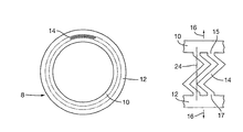
- FIG. 1 shows diagrammatically a suspension according to the invention for a deformable bimorph mirror
- FIG. 2 shows part of the structure of FIG. 1 , together with other structures not according to the invention for comparison purposes.
- FIGS. 3 and 4 show a mirror assembly according to the invention.
- FIGS. 5 and 6 show modifications of the embodiment of FIGS. 3 and 4 .
- FIGS. 7 and 8 show a further embodiment of the invention
- FIGS. 9 and 10 show another embodiment
- FIG. 11 shows yet further embodiments.
- a suspension 8 for a deformable bimorph mirror comprises an inner ring 10 adapted to be fixed to the periphery of a circular bimorph mirror, an outer ring 12 adapted to be fixed to support structure for the mirror and, extending between respective radially-aligned points 15 , 16 on the two rings, a number of serpentine suspension elements 14 ( FIG. 2 b ).
- the elements 14 are angularly spaced apart regularly around the annular gap between the rings 10 , 12 .
- the ring 10 is sized to accommodate a substrate of 18 mm diameter, and the suspension is etched or laser cut from 50 ⁇ m thick copper sheet.
- the suspension elements are of serpentine form; specifically in this case they are of herringbone or zig-zag shape. They could alternatively be of curved or sinuous serpentine form.
- the elements 14 are sufficiently serpentine so that relative radial movement of the rings 10 , 12 due to deformation of the mirror, which tends to increase the size of the annular gap between them, is accommodated by the elements 14 bending so as to tend to straighten.
- This variation in the curvature of the serpentine elements presents only a relatively low stiffness (high compliance) to the tensile force applied to them and thus the edge of the mirror to which the ring 10 is attached is relatively free to move radially.
- the structure also has low stiffness against bending out of its plane, so that rotation of the edge of the bimorph mirror can be accommodated.
- the combination of bending flexibility in two directions permits the edge of the mirror also to move axially out of the plane of the suspension.
- FIG. 2 a shows by way of contrast portions of rings 10 , 12 which are joined by straight elements 18 .
- FIG. 2 c shows elements 20 of slightly serpentine form. However they are insufficiently serpentine to provide the required compliance, because there is a continuous straight path 22 through the material of the elements normal to the rings 10 , 12 . The elements thus will resist the deformation 16 in tension as if they were straight as in FIG. 12 a , rather than by substantially in-plane bending of the zig-zag portions.
- FIG. 3 shows the suspension 8 installed as part of a self-deforming bimorph mirror assembly.
- the mirror consists of a circular passive substrate 28 having a mirror surface 30 .
- a piezo-electric (here PZT) layer 32 formed as a number of separate piezo-electric elements for locally applying bending forces to the substrate 28 .
- the circumferential edge of the substrate 28 is glued at 34 to the ring 10 of the suspension 8 .
- the ring 12 is glued at 38 to a fixed base structure 36 .
- the suspension 8 is of copper, so as to provide a conductive path for dissipating heat generated in the substrate 28 , for example by radiation incident on the mirror.
- the glue used to attach the suspension 8 to the substrate 28 and the base structure 36 is of a thermally-conductive type, for example EP30AN-1 by Master Bond Inc.
- Other materials which could be used for the suspension 8 are, for example, glass, silicon, Kapton® or other polyimide, silicon carbide or diamond, the latter two materials being produced for example by plasma enhanced chemical vapour deposition.
- the piezo-electric elements are addressed via a flexible printed circuit 40 , FIG. 4 .
- a gap is provided in the suspension 8 to permit the flexible circuit to access the piezo-electric elements.
- the illustrated arrangement results in the mirror substrate 28 being supported asymmetrically around its circumference, which may degrade its deformation performance. This disadvantage can be reduced if the flexible circuit is divided into several branches which access the piezo-electric elements via several gaps in the suspension 8 evenly distributed around its circumference. It will be appreciated that the mirror substrate 28 is deformed solely by the agency of the piezo-electric elements.
- the suspension 8 has a purely passive role, and is not used to transmit deforming forces to the mirror.
- FIG. 5 shows an alternative arrangement in which the flexible circuit 40 is bent so as to access the piezo-electric elements without the need for gaps in the suspension 8 .
- FIG. 6 shows a further variation in which the suspension 8 is mounted below the base structure 36 so that the flexible circuit 40 can be taken out radially from the piezo-electric elements. The generally planar arrangement of the mirror assembly then is preserved.
- the inner ring 10 of the suspension is formed directly as the outer part of the substrate 28 of the mirror. This avoids the need for the glued joint 34 , and can improve the thermal conductivity of the mirror and suspension assembly.
- the ring 12 is bonded to the base structure 36 as already described.
- the substrate 28 can be of copper, or if high thermal loading is expected, it could be of silicon, silicon carbide or diamond.
- the substrate can be made as a lamination of two discs, one of which extends radially beyond the other and provides the support elements 14 .
- the two laminated discs need not be of the same material, provided that the materials have very similar thermal expansion coefficients.
- the suspension 8 may be integrated into the substrate 28 in the same way in the embodiments of FIGS. 5 and 6 .
- FIGS. 9 and 10 show another embodiment of the invention in which the suspension is integrated with the flexible circuit 40 .
- the suspension elements 14 are made of the base material of the flexible circuit, for example polyimide or PEEK film.
- Conductive tracks 42 FIG. 10 ) advantageously can be printed onto the suspension elements 14 to address the piezo-electric elements.
- the flexible circuit is divided and distributed so that the suspension elements are evenly spaced around the mirror.
- straight supporting elements 44 extend obliquely between rings 10 and 12 , instead of being normal to the rings as in FIG. 2 a , and parallel to the applied deformation 16 .
- the elements 44 thus extend between points 46 and 48 on the two rings which are spaced transversely (laterally) of each other with respect to the relative radial movement of the rings 10 and 12 .
- the points 46 , 48 are relatively offset sufficiently for there to be no continuous path radially between the rings through the material of the elements 44 , as already discussed in the content of FIG. 2 .
- Relative radial movement 16 of the rings thus is accommodated by bending of the elements 44 , principally about their points of attachment to the rings 10 , 12 with relatively low stiffness.
- FIG. 11 b shows a modification of the embodiment of FIG. 11 a .
- the elements 44 follow a curved (in this example, serpentine) path between points 46 , 48 , at least the central section 50 of the elements extending obliquely between the rings. Movement 16 is again accommodated by bending of the elements 44 , the deformation of the elements 44 being such that they tend to straighten.
- FIG. 11 c shows a limiting case of the arrangement of FIG. 11 b .
- the serpentine elements 44 have two 90° bends 51 so that the central section 50 extends fully transversely of the radial movement of the rings 10 , 12 .
- the necessary compliance is achieved by bending of the elements in the region of the right-angle bends 51 . It will be appreciated that when arranged around the annular space between the rings 10 , 12 , the elements fall into groups each exhibiting a staircase pattern, the pattern repeating itself at intervals.
- FIGS. 2 b and 11 all have the advantage that the elements 14 , 44 extend parallel to each other and thus can be provided in a close-packed array between the rings 10 , 12 . This can provide a substantial cross-sectional area of material for conducting heat from the mirror substrate to the structure 36 .
- FIG. 2 b has the further advantage that the double-bend serpentine form of each element 14 , plus it being attached to the rings 10 , 12 at points 15 , 17 which are radially aligned with each other, results in the structure being torsionally balanced when subjected to deformation in the direction 16 .
- the embodiments of FIG. 11 are not so balanced; relative separating movement 16 of the rings 10 , 12 will tend to result in relative rotation of the rings as shown by arrows 52 , 54 . Whilst the rotation may be second order in many circumstances, it may result in some reduction in the accuracy of control of the reflective performance of the mirror.
- a passive suspension for a bimorph or other self-deforming mirror includes elements e.g. of herringbone shape extending between the edge of the mirror substrate and support structure.
- the elements have portions direction transversely (e.g. obliquely) relative to a direction of relative movement between the mirror edge and the support structure, so as to accommodate the movement by bending.
Abstract
Description
-
- imaging, for example deformable mirrors are used in astronomy to improve the resolution of earth-based telescopes that are otherwise affected by atmospheric distortions;
- laser sensing, where the amount of last light that can be delivered onto a target is significantly increased by using a deformable mirror to correct for atmospheric distortions—this enables either better information to be obtained or objects to be identified at a greater range; and
- laser generation, where a deformable mirror can be used intra-cavity within a high power laser to counter the thermal blooming that can be otherwise induced by the high concentration of laser light inside the cavity.
Claims (20)
Applications Claiming Priority (7)
| Application Number | Priority Date | Filing Date | Title |
|---|---|---|---|
| GB08212102 | 2008-11-20 | ||
| GB0821210A GB0821210D0 (en) | 2008-11-20 | 2008-11-20 | Deformable mirror suspension |
| EP08275078 | 2008-11-20 | ||
| EP082750787 | 2008-11-20 | ||
| GB0821210.2 | 2008-11-20 | ||
| EP08275078A EP2189832A1 (en) | 2008-11-20 | 2008-11-20 | Deformable Mirror Suspension |
| PCT/GB2009/051550 WO2010058204A1 (en) | 2008-11-20 | 2009-11-17 | Deformable mirror suspension |
Publications (2)
| Publication Number | Publication Date |
|---|---|
| US20110222177A1 US20110222177A1 (en) | 2011-09-15 |
| US8699113B2 true US8699113B2 (en) | 2014-04-15 |
Family
ID=41404432
Family Applications (1)
| Application Number | Title | Priority Date | Filing Date |
|---|---|---|---|
| US13/129,563 Expired - Fee Related US8699113B2 (en) | 2008-11-20 | 2009-11-17 | Deformable mirror suspension |
Country Status (4)
| Country | Link |
|---|---|
| US (1) | US8699113B2 (en) |
| EP (1) | EP2353043A1 (en) |
| AU (1) | AU2009316996B2 (en) |
| WO (1) | WO2010058204A1 (en) |
Families Citing this family (1)
| Publication number | Priority date | Publication date | Assignee | Title |
|---|---|---|---|---|
| FR3100344B1 (en) * | 2019-08-30 | 2021-09-24 | Alpao | SIMPLIFIED CONSTRUCTION ADAPTIVE OPTICAL DEVICE AND ASSOCIATED MANUFACTURING PROCESS |
Citations (15)
| Publication number | Priority date | Publication date | Assignee | Title |
|---|---|---|---|---|
| JPH03296008A (en) | 1990-04-16 | 1991-12-26 | Toshiba Corp | Mirror device |
| EP0615147A1 (en) | 1992-01-16 | 1994-09-14 | Texas Instruments Incorporated | Low reset voltage process for DMD |
| EP1014139A2 (en) | 1998-12-23 | 2000-06-28 | Carl Zeiss | Optical system, especially for a projection exposure system for microlithography, having a optical mount comprising actuators |
| US6384952B1 (en) | 1997-03-27 | 2002-05-07 | Mems Optical Inc. | Vertical comb drive actuated deformable mirror device and method |
| US20030053186A1 (en) * | 2001-09-19 | 2003-03-20 | Olympus Optical Co., Ltd. | Movable structure, and deflection mirror element, optical switch element and shape variable mirror including the movable structure |
| WO2004057408A2 (en) | 2002-12-23 | 2004-07-08 | Bea Systems Plc | Deformable-mirror cooling |
| WO2004057407A1 (en) | 2002-12-23 | 2004-07-08 | Bae Systems Plc | Deformable mirror |
| US20040160118A1 (en) | 2002-11-08 | 2004-08-19 | Knollenberg Clifford F. | Actuator apparatus and method for improved deflection characteristics |
| US20040245888A1 (en) | 2003-06-05 | 2004-12-09 | Aksyuk Vladimir A. | Deformable MEMS mirror |
| US6838738B1 (en) | 2001-09-21 | 2005-01-04 | Dicon Fiberoptics, Inc. | Electrostatic control of micro-optical components |
| US20050052761A1 (en) | 2003-09-04 | 2005-03-10 | Bennett Optical Research, Inc. | Active/adaptive actuator design of an adaptive optic mirror |
| US20050200938A1 (en) | 2004-03-09 | 2005-09-15 | Greywall Dennis S. | MEMS device for an adaptive optics mirror |
| US7068415B2 (en) | 2002-01-29 | 2006-06-27 | Matsushita Electric Industrial Co., Ltd. | Deformable mirror and optical controller including the deformable mirror |
| EP1676163A2 (en) | 2003-10-20 | 2006-07-05 | BAE Systems PLC | Improvements relating to deformable mirror holders |
| US20070165297A1 (en) | 2005-12-16 | 2007-07-19 | Thilo Sandner | Microoptic reflecting component |
-
2009
- 2009-11-17 US US13/129,563 patent/US8699113B2/en not_active Expired - Fee Related
- 2009-11-17 AU AU2009316996A patent/AU2009316996B2/en not_active Ceased
- 2009-11-17 EP EP09756351A patent/EP2353043A1/en not_active Withdrawn
- 2009-11-17 WO PCT/GB2009/051550 patent/WO2010058204A1/en active Application Filing
Patent Citations (15)
| Publication number | Priority date | Publication date | Assignee | Title |
|---|---|---|---|---|
| JPH03296008A (en) | 1990-04-16 | 1991-12-26 | Toshiba Corp | Mirror device |
| EP0615147A1 (en) | 1992-01-16 | 1994-09-14 | Texas Instruments Incorporated | Low reset voltage process for DMD |
| US6384952B1 (en) | 1997-03-27 | 2002-05-07 | Mems Optical Inc. | Vertical comb drive actuated deformable mirror device and method |
| EP1014139A2 (en) | 1998-12-23 | 2000-06-28 | Carl Zeiss | Optical system, especially for a projection exposure system for microlithography, having a optical mount comprising actuators |
| US20030053186A1 (en) * | 2001-09-19 | 2003-03-20 | Olympus Optical Co., Ltd. | Movable structure, and deflection mirror element, optical switch element and shape variable mirror including the movable structure |
| US6838738B1 (en) | 2001-09-21 | 2005-01-04 | Dicon Fiberoptics, Inc. | Electrostatic control of micro-optical components |
| US7068415B2 (en) | 2002-01-29 | 2006-06-27 | Matsushita Electric Industrial Co., Ltd. | Deformable mirror and optical controller including the deformable mirror |
| US20040160118A1 (en) | 2002-11-08 | 2004-08-19 | Knollenberg Clifford F. | Actuator apparatus and method for improved deflection characteristics |
| WO2004057407A1 (en) | 2002-12-23 | 2004-07-08 | Bae Systems Plc | Deformable mirror |
| WO2004057408A2 (en) | 2002-12-23 | 2004-07-08 | Bea Systems Plc | Deformable-mirror cooling |
| US20040245888A1 (en) | 2003-06-05 | 2004-12-09 | Aksyuk Vladimir A. | Deformable MEMS mirror |
| US20050052761A1 (en) | 2003-09-04 | 2005-03-10 | Bennett Optical Research, Inc. | Active/adaptive actuator design of an adaptive optic mirror |
| EP1676163A2 (en) | 2003-10-20 | 2006-07-05 | BAE Systems PLC | Improvements relating to deformable mirror holders |
| US20050200938A1 (en) | 2004-03-09 | 2005-09-15 | Greywall Dennis S. | MEMS device for an adaptive optics mirror |
| US20070165297A1 (en) | 2005-12-16 | 2007-07-19 | Thilo Sandner | Microoptic reflecting component |
Non-Patent Citations (5)
| Title |
|---|
| British Search Report in related application No. 0821210.2 mailed Mar. 2, 2009. |
| European Search Report in related application 08275078.7 dated Apr. 27, 2009. |
| Faculty of Physical Sciences: Department of Physics; Research: Photonics, Imperial College London, 2007. |
| International Preliminary Report on Patentability in related application No. PCT/GB2009/051550 mailed Jun. 3, 2011. |
| International Search Report in related application No. PCT/GB2009/051550 mailed Dec. 23, 2009. |
Also Published As
| Publication number | Publication date |
|---|---|
| US20110222177A1 (en) | 2011-09-15 |
| WO2010058204A1 (en) | 2010-05-27 |
| AU2009316996A1 (en) | 2010-05-27 |
| AU2009316996B2 (en) | 2013-05-16 |
| EP2353043A1 (en) | 2011-08-10 |
Similar Documents
| Publication | Publication Date | Title |
|---|---|---|
| JP4972774B2 (en) | Micro scanner and optical apparatus provided with the same | |
| EP1364244B1 (en) | Deformable curvature mirror | |
| US20100103522A1 (en) | Variable spectral element | |
| US7271958B2 (en) | Diffractive light modulator | |
| US7708415B2 (en) | Mirror structure having piezoelectric element bonded to a mirror substrate | |
| US9395536B2 (en) | Optical deflector including separated piezoelectric portions on piezoelectric actuators and its designing method | |
| EP1576408B1 (en) | Deformable mirror | |
| US8570637B2 (en) | Micromechanical element | |
| US7490947B2 (en) | Microoptic reflecting component | |
| JP4972789B2 (en) | Micro scanner and optical apparatus provided with the same | |
| US8699113B2 (en) | Deformable mirror suspension | |
| KR100230723B1 (en) | Mosaic adaptive bimorph mirror | |
| KR100570543B1 (en) | Active mirror | |
| KR101130119B1 (en) | Optical Structure for Aerospace Engineering | |
| EP2189832A1 (en) | Deformable Mirror Suspension | |
| US7740363B2 (en) | Deformable-mirror holder | |
| EP3667268A1 (en) | Light detector | |
| US20030030922A1 (en) | Mirror for reflecting electromagnetic radiation as well as illumination and imaging method employing the same | |
| CN111751984A (en) | Scanning light imaging display device | |
| CN111751923B (en) | Optical fiber and scanning light imaging display device | |
| US6469845B1 (en) | Flexible lens mount | |
| JP2014052572A5 (en) | ||
| WO2022224573A1 (en) | Drive element and light deflection element | |
| US20100172044A1 (en) | Mount for positioning an optical element | |
| JP2023548930A (en) | Actively deformable metamirror |
Legal Events
| Date | Code | Title | Description |
|---|---|---|---|
| AS | Assignment |
Owner name: BAE SYSTEMS PLC, UNITED KINGDOM Free format text: ASSIGNMENT OF ASSIGNORS INTEREST;ASSIGNORS:GRIFFITH, MICHAEL STEWART;LAYCOCK, LESLIE CHARLES;ARCHER, NICHOLAS JOHN;REEL/FRAME:026376/0965 Effective date: 20091125 |
|
| FEPP | Fee payment procedure |
Free format text: PAYOR NUMBER ASSIGNED (ORIGINAL EVENT CODE: ASPN); ENTITY STATUS OF PATENT OWNER: LARGE ENTITY |
|
| STCF | Information on status: patent grant |
Free format text: PATENTED CASE |
|
| MAFP | Maintenance fee payment |
Free format text: PAYMENT OF MAINTENANCE FEE, 4TH YEAR, LARGE ENTITY (ORIGINAL EVENT CODE: M1551) Year of fee payment: 4 |
|
| FEPP | Fee payment procedure |
Free format text: MAINTENANCE FEE REMINDER MAILED (ORIGINAL EVENT CODE: REM.); ENTITY STATUS OF PATENT OWNER: LARGE ENTITY |
|
| LAPS | Lapse for failure to pay maintenance fees |
Free format text: PATENT EXPIRED FOR FAILURE TO PAY MAINTENANCE FEES (ORIGINAL EVENT CODE: EXP.); ENTITY STATUS OF PATENT OWNER: LARGE ENTITY |
|
| STCH | Information on status: patent discontinuation |
Free format text: PATENT EXPIRED DUE TO NONPAYMENT OF MAINTENANCE FEES UNDER 37 CFR 1.362 |
|
| FP | Lapsed due to failure to pay maintenance fee |
Effective date: 20220415 |