US8677952B2 - Compound drive for the sleeve valve of an engine - Google Patents
Compound drive for the sleeve valve of an engine Download PDFInfo
- Publication number
- US8677952B2 US8677952B2 US13/147,372 US201013147372A US8677952B2 US 8677952 B2 US8677952 B2 US 8677952B2 US 201013147372 A US201013147372 A US 201013147372A US 8677952 B2 US8677952 B2 US 8677952B2
- Authority
- US
- United States
- Prior art keywords
- sleeve
- drive
- sleeve valve
- pin
- valve engine
- Prior art date
- Legal status (The legal status is an assumption and is not a legal conclusion. Google has not performed a legal analysis and makes no representation as to the accuracy of the status listed.)
- Expired - Fee Related, expires
Links
Images


Classifications
-
- F—MECHANICAL ENGINEERING; LIGHTING; HEATING; WEAPONS; BLASTING
- F01—MACHINES OR ENGINES IN GENERAL; ENGINE PLANTS IN GENERAL; STEAM ENGINES
- F01L—CYCLICALLY OPERATING VALVES FOR MACHINES OR ENGINES
- F01L1/00—Valve-gear or valve arrangements, e.g. lift-valve gear
- F01L1/02—Valve drive
-
- F—MECHANICAL ENGINEERING; LIGHTING; HEATING; WEAPONS; BLASTING
- F01—MACHINES OR ENGINES IN GENERAL; ENGINE PLANTS IN GENERAL; STEAM ENGINES
- F01L—CYCLICALLY OPERATING VALVES FOR MACHINES OR ENGINES
- F01L1/00—Valve-gear or valve arrangements, e.g. lift-valve gear
- F01L1/02—Valve drive
- F01L1/024—Belt drive
-
- F—MECHANICAL ENGINEERING; LIGHTING; HEATING; WEAPONS; BLASTING
- F01—MACHINES OR ENGINES IN GENERAL; ENGINE PLANTS IN GENERAL; STEAM ENGINES
- F01L—CYCLICALLY OPERATING VALVES FOR MACHINES OR ENGINES
- F01L5/00—Slide valve-gear or valve-arrangements
- F01L5/04—Slide valve-gear or valve-arrangements with cylindrical, sleeve, or part-annularly shaped valves
- F01L5/06—Slide valve-gear or valve-arrangements with cylindrical, sleeve, or part-annularly shaped valves surrounding working cylinder or piston
- F01L5/08—Arrangements with several movements or several valves, e.g. one valve inside the other
- F01L5/10—Arrangements with several movements or several valves, e.g. one valve inside the other with reciprocating and other movements of the same valve
-
- F—MECHANICAL ENGINEERING; LIGHTING; HEATING; WEAPONS; BLASTING
- F01—MACHINES OR ENGINES IN GENERAL; ENGINE PLANTS IN GENERAL; STEAM ENGINES
- F01L—CYCLICALLY OPERATING VALVES FOR MACHINES OR ENGINES
- F01L1/00—Valve-gear or valve arrangements, e.g. lift-valve gear
- F01L1/02—Valve drive
- F01L1/026—Gear drive
-
- F—MECHANICAL ENGINEERING; LIGHTING; HEATING; WEAPONS; BLASTING
- F01—MACHINES OR ENGINES IN GENERAL; ENGINE PLANTS IN GENERAL; STEAM ENGINES
- F01L—CYCLICALLY OPERATING VALVES FOR MACHINES OR ENGINES
- F01L5/00—Slide valve-gear or valve-arrangements
- F01L5/04—Slide valve-gear or valve-arrangements with cylindrical, sleeve, or part-annularly shaped valves
- F01L5/06—Slide valve-gear or valve-arrangements with cylindrical, sleeve, or part-annularly shaped valves surrounding working cylinder or piston
Definitions
- This invention concerns sleeve valve engines and particularly to the drive imparted to the sleeve valve itself.
- Sleeve valve engines display certain limitations, one of which is the shape of the port opening and closing path imposed by a single sleeve crank joined to the trailing end of the sleeve by a ball and socket.
- the path is elliptical in shape. It is preferable to place the topmost piston ring close to the piston crown to ensure low emissions.
- a sleeve valve engine with opposed cylinders has a sleeve valve drive which uses a pair of ring gears to rotate the sleeve for each of the cylinders.
- Axial movement of the sleeve is imparted by a rotating disc adjacent to the sleeves which projects into a helical groove in the end of the sleeve.
- the pitch and length of the groove is slight so as to cause sufficient reciprocation to rub away carbon deports which would otherwise collect in the sleeve ports. This is not effective for assisting with advantageous port shape.
- the apparatus aspect of the invention provides a sleeve valve engine wherein the sleeve valve which opens and closes the ports is driven by a first sleeve drive which imparts reciprocatory motion to the sleeve while a second sleeve drive imparts partial rotation to the sleeve.
- a block adjacent the sleeve describes an eccentric path in order to reciprocate the sleeve and the block engages a follower projecting from the sleeve which allows the sleeve to describe an arcuate path while reciprocating.
- the follower has a thrust face at the leading end and a like thrust face at the trailing end. The arc of movement corresponds to the sleeve rotation suffices to cover and uncover the ports in the cylinder head.
- the thrust faces may be mutually parallel and disposed transversely to the axis of reciprocation.
- the second drive comprises an axially disposed slide projecting from the sleeve with a substantially cylindrical surface interrupted by a gap, a pin which describes eccentric motion and projects into the gap and a head carried by the pin, the opposite ends of which are curved to contact the cylindrical surface, whereby the pin imparts arcuate motion to the sleeve while allowing the slide to reciprocate in response to the first drive.
- the block may be eccentrically mounted on a first gear wheel rotating on an axis disposed at 90° to the cylinder axis.
- the pin in the second drive may be eccentrically mounted on a second gear wheel rotating on the same or different axis also disposed at 90° to the cylinder axis and lying diametrically opposite the first gear wheel. While this 180° arrangement of the first and second gear wheels is convenient, the drives work equally well if the angle is smaller than 180°.
- the first and second gear wheels may be part of a right angle drives from the half speed valve motion gears which are present in all valve engines which depend on the Otto cycle.
- the first and second drives contribute to the sleeve motion simultaneously and together impose an elliptical path on the sleeve.
- the valve motion gears are connected for rotation in unison by a chain or toothed belt. The path is however modified over that known in the prior art and the improved elliptical path allows variation in port design.
- There may be multiple ports in the sleeve preferably up to seven.
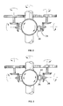
- FIG. 1 is a diagrammatic perspective of the working parts.
- FIG. 2 is a diagrammatic plan of the working parts of FIG. 1 with sleeve rotation at 80° to the crankshaft.
- FIG. 3 is a diagrammatic plan of the working parts of FIG. 1 with sleeve rotation at 90° to the crankshaft.
- FIG. 4 is a diagrammatic plan of the working parts of FIG. 1 with sleeve rotation at 100° to the crankshaft.
- FIGS. 5 , 6 and 7 are side views of the sleeve drives in FIGS. 2 , 3 and 4 .
- FIG. 8 is an underneath perspective of a variant showing toothed belt drive.
- FIG. 9 is a perspective of the wheel which gives axial drive to the sleeve.
- FIG. 10 is a view of the reverse face of the wheel shown in FIG. 9 .
- FIG. 11 is a view of the wheel of FIGS. 9 and 10 with the block attached.
- FIG. 12 is a section through FIG. 11 showing the attached bevel gear.
- FIG. 13 is a front view of the wheel and block in a different phase from FIG. 11 .
- FIG. 14 is a side view showing the bevel gears and the wheel and blocks for axial sleeve motion.
- FIG. 15 is a diagrammatic plan of the drive to the sleeve for rotary sleeve motion.
- FIG. 16 is a plan view of the drive shown in FIG. 15 but as it appears in the engine.
- FIG. 17 is a section through FIG. 16 .
- the cylinder 2 has pairs of apertures 4 arranged around the circumference which register with ports in the cylinder block which connect with fuel/air supply (not shown) and exhaust ducts.
- Sleeve valve 6 likewise has pairs of apertures which move in and out of register with the cylinder apertures and connect the cylinder to inlet and exhaust in accordance with the Otto cycle.
- the lower end of the sleeve valve extends beyond the end of the cylinder by about 30 mm in order to accommodate the sleeve drive taken from crankshaft 8 by toothed wheels 10 , 12 and a common toothed belt 14 .
- Wheel 12 rotates clockwise and drives bevel gear 16 and thereby bevel gear 18 .
- Bevel gear 18 lies adjacent the moving sleeve valve and has an eccentric pin 20 which projects between parallel thrust faces 22 , 24 of a follower 26 projecting from the outer surface of the sleeve valve.
- the metal faces are sufficiently long to remain in contact over 20° of sleeve valve rotation with a metal block 28 engaged by pin 20 .
- Block 28 gives better area of contact with the thrust faces than the pin alone.
- Wheel 10 rotates clockwise and drives bevel gear 30 and thereby bevel gear 32 .
- Bevel gear 32 likewise lies adjacent the moving sleeve valve at 180° to bevel gear 18 .
- Bevel gear 32 drives eccentric pin 34 .
- Split cylindrical sleeve 36 is fixed to the outer surface of sleeve valve 6 diametrically opposite the follower 26 .
- Eccentric pin 34 projects through a gap 38 in the split sleeve and engages rocker 40 .
- Rocker 40 has curved end faces equidistant from the pin 34 which mate with the internal cylindrical surface of the sleeve 36 .
- the bevel gears 18 , 32 are co-linear and disposed at 90° to the crankshaft axis. A 10° rotation clockwise followed by a 10° reversal and 10° rotation anticlockwise is within the travel of the block 28 and the rocker 40 .
- the follower 26 and split sleeve 36 add little to the mass of the sleeve valve but improve engine performance in that they permit separation of the sleeve motion into reciprocating and rotational components. Separation of these components into two drives permits variation in port design.
- FIG. 8 the way in which the toothed belt 14 takes drive from the crankshaft is shown. Idler 42 allows belt adjustment.
- pulley bearing 50 lies between circlips 52 , 54 on shaft 56 which is rotated by pulley 12 .
- a lubrication hole 58 enters bearing 50 .
- the opposite end of shaft 56 runs in needle bearing 60 .
- Shaft 62 extends at 90° to shaft 56 in order to support bevel gear 18 .
- Several tapered head screws 64 clamp thrust plate 66 to bevel gear 18 .
- the two faces of the thrust plate are shown in FIGS. 9 and 10 .
- the bearing is 90 mm in diameter but only the outermost 10 mm takes thrust from adjacent components on two faces.
- Slide block 28 is carried on pin 12 which extends at 90° from thrust bearing 66 .
- FIG. 12 shows an oil passage 68 extending from the spigot 70 of the bevel gear 18 to the pin bore 72 . Exit hole 74 returns oil to the sump.
- FIG. 15 the connection between pin 34 and bronze rocker 40 is shown diagrammatically.
- housing 80 supports the same arrangement of angled shafts as in the axial sleeve drive.
- Shaft 82 turns in bearing 84 which abuts the annular face of a shoulder.
- Bevel gear 30 abuts the opposite face of the shoulder.
- the tapered end of shaft 82 projects from the housing and receives the end of drive pulley 10 .
- Pin 34 is hollow and allows oil to escape from the end of the pin into rocker 40 and to lubricate split sleeve 36 . Oil leaves the housing through exit hole 86 .
- Thrust washer 88 is imprisoned between bevel gear 32 and rocker 40 .
- Pulley 12 rotates clockwise and drives the shaft 56 which is supported between ball bearing 50 and needle bearing 60 .
- Bearing 50 controls the axial and radial forces on this shaft.
- Bevel gear 16 is an interference press fit onto shaft 56 .
- the torque can be transmitted purely on the interference but a woodroff key can be used for added drive security.
- the developed thrust force on bevel gear 16 is supported by the shaft shoulder.
- Bevel gear 18 is secured to the shaft 62 with twelve M5 tapered head screws 64 . This arrangement is well proven in the attachment of crown wheels in a motor vehicle rear wheel drive planetary differential gear centre. Alternatively the shaft and bevel gear could be manufactured in one unit.
- the shaft 62 is supported on a plain journal bearing.
- the face 90 , face 92 and the surface of the shaft 62 receive oil pressure feed.
- FIG. 17 shows a section view of components. These three surfaces maintain accurate shaft position against the axial inertia force of accelerating and de-accelerating the sleeve 6 and the bevel gear meshing forces.
- An internal oil passage 68 also feeds the offset pin 2 and therefore the internal hole of the bronze sliding block 28 .
- This block also has a communicating hole 90 that supplies oil to the sliding surfaces 22 , 24 on bronze/sleeve interface. In this way all sliding surfaces receive oil pressure feed.
- the oil pressure feed also supplies an oil spray into the meshing area of the bevel gears.
- the parallel thrust faces are sufficiently long to remain in contact over 20° of the sleeve valve rotation with the bronze block 28 .
- the maximum inertia forces occur at TDC and BDC where the parallel faces are centered on the bronze block 28 .
- Wheel 10 rotates clockwise and drives bevel gear 30 via shaft 70 and thereby bevel gear 32 .
- Bevel gear 32 likewise lies adjacent to the moving sleeve valve at 180° to bevel gear 18 .
- the axial and rotational gear sets do not necessarily need to be 180° apart.
- Bevel 32 drives eccentric pin 34 .
- Split cylindrical sleeve 36 is fixed to the outer surface of sleeve valve 6 diametrically opposite the follower 26 .
- Eccentric pin 34 projects through a gap 38 in the split sleeve and engages bronze rocker 40 .
- Rocker 40 has cylindrical faces equidistant from the pin 34 which mate with the internal cylindrical surface of the sleeve 36 .
- the shaft 82 for the rotational motion is identical to the shaft 56 of the axial motion and is supported by the identical journal oil pressure feed surfaces.
- the inertia loading on the bronze rocker 40 reaches maximum value when the sleeve 6 has reached its most rotational limit.
- the maximum bearing area at this angle is available between split sleeve 36 and bronze circular bush 40 to keep the stresses within acceptable levels.
Landscapes
- Engineering & Computer Science (AREA)
- Mechanical Engineering (AREA)
- General Engineering & Computer Science (AREA)
- Valve-Gear Or Valve Arrangements (AREA)
- Transmission Devices (AREA)
- Valve Device For Special Equipments (AREA)
Abstract
Description
- 1. The port shape can be tall and narrow. Narrow ports allow a ring position high up on the piston closer to the crown.
- 2. The additional components are not complicated.
Claims (7)
Applications Claiming Priority (3)
| Application Number | Priority Date | Filing Date | Title |
|---|---|---|---|
| AU2009900735 | 2009-02-20 | ||
| AU2009900735A AU2009900735A0 (en) | 2009-02-20 | Compound drive for the sleeve valve of an engine | |
| PCT/AU2010/000191 WO2010094078A1 (en) | 2009-02-20 | 2010-02-22 | Compound drive for the sleeve valve of an engine |
Publications (2)
| Publication Number | Publication Date |
|---|---|
| US20110283962A1 US20110283962A1 (en) | 2011-11-24 |
| US8677952B2 true US8677952B2 (en) | 2014-03-25 |
Family
ID=42633359
Family Applications (1)
| Application Number | Title | Priority Date | Filing Date |
|---|---|---|---|
| US13/147,372 Expired - Fee Related US8677952B2 (en) | 2009-02-20 | 2010-02-22 | Compound drive for the sleeve valve of an engine |
Country Status (6)
| Country | Link |
|---|---|
| US (1) | US8677952B2 (en) |
| EP (1) | EP2399008B1 (en) |
| JP (1) | JP5550662B2 (en) |
| CN (1) | CN102224324B (en) |
| AU (1) | AU2010215079B2 (en) |
| WO (1) | WO2010094078A1 (en) |
Families Citing this family (2)
| Publication number | Priority date | Publication date | Assignee | Title |
|---|---|---|---|---|
| CN106437927A (en) * | 2016-11-10 | 2017-02-22 | 安徽工程大学 | Rotary net type valve timing mechanism |
| RU2734566C1 (en) * | 2020-04-28 | 2020-10-20 | Акционерное общество "Северный пресс" | Two-stroke engine with sleeve gas distribution |
Citations (4)
| Publication number | Priority date | Publication date | Assignee | Title |
|---|---|---|---|---|
| GB191207942A (en) | 1912-03-01 | 1913-01-16 | Auguste Guiot | Improvements in Vibration Damping Devices more particularly applicable to Vehicle Springs. |
| GB295013A (en) | 1927-08-06 | 1929-03-14 | British Continental Motors Ltd | Improvements in sleeve valve internal combustion engines |
| GB511507A (en) | 1937-02-19 | 1939-08-21 | Marius Jean Baptiste Barbarou | Improvements in or relating to two-stroke internal combustion engines |
| WO2007057660A1 (en) | 2005-11-18 | 2007-05-24 | Lotus Cars Limited | Reciprocating piston sleeve valve engine |
Family Cites Families (5)
| Publication number | Priority date | Publication date | Assignee | Title |
|---|---|---|---|---|
| GB191107942A (en) * | 1911-03-30 | 1912-02-01 | Argylls Ltd | Improvements in the Valve Mechanism of Internal Cumbustion Engines. |
| GB191507942A (en) * | 1915-05-28 | 1916-03-16 | Parkinson & W & B Cowan Ltd | Improvements in Vaporisers for Oil Lamps. |
| US1749701A (en) * | 1928-04-13 | 1930-03-04 | Gilbert Edward Leslie | Single-sleeve-valve engine |
| JPS6398411U (en) * | 1986-12-17 | 1988-06-25 | ||
| JPS6398414U (en) * | 1986-12-18 | 1988-06-25 |
-
2010
- 2010-02-22 CN CN201080008002.5A patent/CN102224324B/en not_active Expired - Fee Related
- 2010-02-22 US US13/147,372 patent/US8677952B2/en not_active Expired - Fee Related
- 2010-02-22 JP JP2011550384A patent/JP5550662B2/en not_active Expired - Fee Related
- 2010-02-22 EP EP10743334.4A patent/EP2399008B1/en not_active Not-in-force
- 2010-02-22 WO PCT/AU2010/000191 patent/WO2010094078A1/en not_active Ceased
- 2010-02-22 AU AU2010215079A patent/AU2010215079B2/en not_active Ceased
Patent Citations (4)
| Publication number | Priority date | Publication date | Assignee | Title |
|---|---|---|---|---|
| GB191207942A (en) | 1912-03-01 | 1913-01-16 | Auguste Guiot | Improvements in Vibration Damping Devices more particularly applicable to Vehicle Springs. |
| GB295013A (en) | 1927-08-06 | 1929-03-14 | British Continental Motors Ltd | Improvements in sleeve valve internal combustion engines |
| GB511507A (en) | 1937-02-19 | 1939-08-21 | Marius Jean Baptiste Barbarou | Improvements in or relating to two-stroke internal combustion engines |
| WO2007057660A1 (en) | 2005-11-18 | 2007-05-24 | Lotus Cars Limited | Reciprocating piston sleeve valve engine |
Also Published As
| Publication number | Publication date |
|---|---|
| EP2399008A4 (en) | 2013-11-06 |
| AU2010215079A1 (en) | 2011-08-18 |
| EP2399008B1 (en) | 2016-11-30 |
| AU2010215079B2 (en) | 2015-05-07 |
| EP2399008A1 (en) | 2011-12-28 |
| JP2012518732A (en) | 2012-08-16 |
| CN102224324A (en) | 2011-10-19 |
| US20110283962A1 (en) | 2011-11-24 |
| CN102224324B (en) | 2014-08-27 |
| JP5550662B2 (en) | 2014-07-16 |
| WO2010094078A1 (en) | 2010-08-26 |
Similar Documents
| Publication | Publication Date | Title |
|---|---|---|
| CA2261596C (en) | Opposed piston combustion engine | |
| US5623894A (en) | Dual compression and dual expansion engine | |
| US5123394A (en) | Rotary reciprocating internal combustion engine | |
| JP2006233976A (en) | Improvement of axial piston rotary engine | |
| US10267225B2 (en) | Internal combustion engine | |
| US6615793B1 (en) | Valveless revolving cylinder engine | |
| JPH01237301A (en) | Power transmission device | |
| US8677952B2 (en) | Compound drive for the sleeve valve of an engine | |
| EP0016826A1 (en) | Rotary engine valve | |
| CN107429582A (en) | Sealing device, modularization rotary valve apparatus and engine | |
| DE102007034941B4 (en) | Rotary motor with rigid connecting rod connection | |
| WO1983000722A1 (en) | Rotary engine valve with improved seals and lubrication system | |
| AU2004258057A1 (en) | Optimized linear engine | |
| EP1304449B1 (en) | Internal combustion engine with rotary valves | |
| KR102286484B1 (en) | Multi-Cylinder Rotary Engine With Triangular Cylinder | |
| EP3682094A1 (en) | Engine with rotating valve assembly | |
| WO2011034657A2 (en) | A supercharged internal combustion engine including a pressurized fluid outlet | |
| US20060219193A1 (en) | Optimized linear engine | |
| RU2263803C1 (en) | Internal combustion engine | |
| US1861440A (en) | Sleeve valve engine | |
| JPH0979019A (en) | Oil supply hole structure of camshaft for multi-cylinder engine | |
| US7331319B1 (en) | Cam hub mounting assembly | |
| EP1304448A1 (en) | Internal combustion engine with rotary valves | |
| US1753226A (en) | Internal-combustion engine | |
| DE10119373A1 (en) | Plate piston IC engine has a reciprocating plate inside cylindrical sector combustions chambers |
Legal Events
| Date | Code | Title | Description |
|---|---|---|---|
| AS | Assignment |
Owner name: GREEN ENERGY GAS ENGINES PTY. LTD., AUSTRALIA Free format text: ASSIGNMENT OF ASSIGNORS INTEREST;ASSIGNORS:BENINCA, JOSEPH ANGELO;JONES, MARK FREDERICK;REEL/FRAME:026683/0611 Effective date: 20110802 |
|
| STCF | Information on status: patent grant |
Free format text: PATENTED CASE |
|
| FEPP | Fee payment procedure |
Free format text: ENTITY STATUS SET TO MICRO (ORIGINAL EVENT CODE: MICR) |
|
| MAFP | Maintenance fee payment |
Free format text: PAYMENT OF MAINTENANCE FEE, 4TH YEAR, MICRO ENTITY (ORIGINAL EVENT CODE: M3551) Year of fee payment: 4 |
|
| AS | Assignment |
Owner name: SLEEVE VALVE ENGINE COMPANY PTY LTD, AUSTRALIA Free format text: ASSIGNMENT OF ASSIGNORS INTEREST;ASSIGNOR:GREEN ENERGY GAS ENGINES PTY. LTD.;REEL/FRAME:055613/0579 Effective date: 20201228 |
|
| FEPP | Fee payment procedure |
Free format text: SURCHARGE FOR LATE PAYMENT, MICRO ENTITY (ORIGINAL EVENT CODE: M3555); ENTITY STATUS OF PATENT OWNER: MICROENTITY |
|
| MAFP | Maintenance fee payment |
Free format text: PAYMENT OF MAINTENANCE FEE, 8TH YEAR, MICRO ENTITY (ORIGINAL EVENT CODE: M3552); ENTITY STATUS OF PATENT OWNER: MICROENTITY Year of fee payment: 8 |
|
| FEPP | Fee payment procedure |
Free format text: MAINTENANCE FEE REMINDER MAILED (ORIGINAL EVENT CODE: REM.); ENTITY STATUS OF PATENT OWNER: MICROENTITY |