US8665470B2 - Method of displaying expected service life values collected by replaceable unit in an electronic device, and a display program - Google Patents
Method of displaying expected service life values collected by replaceable unit in an electronic device, and a display program Download PDFInfo
- Publication number
- US8665470B2 US8665470B2 US12/710,644 US71064410A US8665470B2 US 8665470 B2 US8665470 B2 US 8665470B2 US 71064410 A US71064410 A US 71064410A US 8665470 B2 US8665470 B2 US 8665470B2
- Authority
- US
- United States
- Prior art keywords
- media
- service life
- expected service
- drive
- unit
- Prior art date
- Legal status (The legal status is an assumption and is not a legal conclusion. Google has not performed a legal analysis and makes no representation as to the accuracy of the status listed.)
- Expired - Fee Related, expires
Links
- 238000000034 method Methods 0.000 title claims description 32
- 238000012545 processing Methods 0.000 claims abstract description 57
- 238000012423 maintenance Methods 0.000 claims abstract description 28
- 230000001186 cumulative effect Effects 0.000 claims abstract description 22
- 238000003860 storage Methods 0.000 claims description 48
- 230000007246 mechanism Effects 0.000 claims description 25
- 238000004891 communication Methods 0.000 claims description 7
- FMINYZXVCTYSNY-UHFFFAOYSA-N Methyldymron Chemical compound C=1C=CC=CC=1N(C)C(=O)NC(C)(C)C1=CC=CC=C1 FMINYZXVCTYSNY-UHFFFAOYSA-N 0.000 description 42
- 230000008569 process Effects 0.000 description 8
- 238000012546 transfer Methods 0.000 description 8
- 230000006870 function Effects 0.000 description 6
- 238000013500 data storage Methods 0.000 description 5
- 238000003825 pressing Methods 0.000 description 3
- 238000010586 diagram Methods 0.000 description 2
- 238000012986 modification Methods 0.000 description 2
- 230000004048 modification Effects 0.000 description 2
- 230000008859 change Effects 0.000 description 1
- 239000003086 colorant Substances 0.000 description 1
- 238000004519 manufacturing process Methods 0.000 description 1
- 238000012544 monitoring process Methods 0.000 description 1
- 230000003287 optical effect Effects 0.000 description 1
Images


Classifications
-
- B—PERFORMING OPERATIONS; TRANSPORTING
- B41—PRINTING; LINING MACHINES; TYPEWRITERS; STAMPS
- B41J—TYPEWRITERS; SELECTIVE PRINTING MECHANISMS, i.e. MECHANISMS PRINTING OTHERWISE THAN FROM A FORME; CORRECTION OF TYPOGRAPHICAL ERRORS
- B41J3/00—Typewriters or selective printing or marking mechanisms characterised by the purpose for which they are constructed
- B41J3/407—Typewriters or selective printing or marking mechanisms characterised by the purpose for which they are constructed for marking on special material
- B41J3/4071—Printing on disk-shaped media, e.g. CDs
-
- B—PERFORMING OPERATIONS; TRANSPORTING
- B41—PRINTING; LINING MACHINES; TYPEWRITERS; STAMPS
- B41J—TYPEWRITERS; SELECTIVE PRINTING MECHANISMS, i.e. MECHANISMS PRINTING OTHERWISE THAN FROM A FORME; CORRECTION OF TYPOGRAPHICAL ERRORS
- B41J3/00—Typewriters or selective printing or marking mechanisms characterised by the purpose for which they are constructed
- B41J3/44—Typewriters or selective printing mechanisms having dual functions or combined with, or coupled to, apparatus performing other functions
- B41J3/46—Printing mechanisms combined with apparatus providing a visual indication
-
- G—PHYSICS
- G11—INFORMATION STORAGE
- G11B—INFORMATION STORAGE BASED ON RELATIVE MOVEMENT BETWEEN RECORD CARRIER AND TRANSDUCER
- G11B17/00—Guiding record carriers not specifically of filamentary or web form, or of supports therefor
- G11B17/08—Guiding record carriers not specifically of filamentary or web form, or of supports therefor from consecutive-access magazine of disc records
- G11B17/10—Guiding record carriers not specifically of filamentary or web form, or of supports therefor from consecutive-access magazine of disc records with horizontal transfer to the turntable from a stack arranged with a vertical axis
-
- G—PHYSICS
- G11—INFORMATION STORAGE
- G11B—INFORMATION STORAGE BASED ON RELATIVE MOVEMENT BETWEEN RECORD CARRIER AND TRANSDUCER
- G11B23/00—Record carriers not specific to the method of recording or reproducing; Accessories, e.g. containers, specially adapted for co-operation with the recording or reproducing apparatus ; Intermediate mediums; Apparatus or processes specially adapted for their manufacture
- G11B23/38—Visual features other than those contained in record tracks or represented by sprocket holes the visual signals being auxiliary signals
- G11B23/40—Identifying or analogous means applied to or incorporated in the record carrier and not intended for visual display simultaneously with the playing-back of the record carrier, e.g. label, leader, photograph
Definitions
- Japanese Patent application No. 2009-042616 is hereby incorporated by reference in its entirety.
- the present invention relates to a method of displaying expected service life values collected for replaceable units in an electronic device, and a display program for the same.
- This maintenance counter information is, however, not displayed to the user of the electronic device (media processing device).
- the electronic device media processing device
- the number of times movable parts inside the media processing device operate, the number of discs produced, and the number of times each drive writes data, are displayed for the user, it is difficult for the user to know when it is time to replace a particular unit (such as the media drive or label printer), that is, when the end of the service life of a replaceable unit is reached.
- a method of displaying expected service life values compiled for individual replacement units of an electronic device, and a display program for the same, according to the present invention enable the user of an electronic device to easily know the replacement time (the end of the service life) of individually replaceable units incorporated in the electronic device.
- a first aspect of the invention is an expected service life value display method for displaying an expected service life value for each replaceable unit in an electronic device having at least a media drive as a replaceable unit, including as steps executed by a host computer connected to the electronic device steps of: acquiring maintenance counter information that is stored in the electronic device and includes a cumulative usage time related to a head of the media drive used with media of a specific type; calculating the (cumulative usage time)/(assured time) as the expected service life value for each head based on the acquired maintenance counter information and an assured time that is preset for each head used with media of the specific type; and displaying the maximum value of the expected service life values calculated for the heads on a display unit as the expected service life of the media drive.
- expected service life values compiled for each replaceable unit of the electronic device are displayed on a display unit with this method of displaying expected service life values, the user can easily know approximately when each replaceable unit must be replaced (the end of the service life) by referring to the service life values displayed on the display unit.
- the maintenance counter information includes a cumulative opening/closing count for a media tray of the media drive
- the display method further includes as steps executed by the host computer steps of: calculating the (cumulative count)/(assured time) as the expected service life value for opening and closing the media tray based on the acquired maintenance counter information and an assured time that is preset for opening and closing the media tray; and displaying the maximum value of the expected service life values calculated for the heads and the expected service life value for opening and closing the media tray on a display unit as the expected service life of the media drive.
- the expected service life value display method enables knowing approximately when each replaceable unit must be replaced (the end of the service life) by also considering the wear of mechanical parts as an indicator of the service life of the media drive.
- the host computer additionally executes steps of acquiring expected service life values for each of the plural media drives, and displaying the expected service life value for each media drive on the display unit.
- the electronic device is a media processing device additionally having a label printer that is a replaceable unit, a media storage unit that stores the media; and a media transportation mechanism that can convey the media to the media drive, the label printer, and the media storage unit;
- the maintenance counter information includes a total print count of the label printer; and the host computer additionally executes a step of displaying the total print count on the display unit.
- the electronic device is a media processing device additionally having a label printer that is a replaceable unit, a media storage unit that stores the media; and a media transportation mechanism that can convey the media to the media drive, the label printer, and the media storage unit;
- the maintenance counter information includes a total print count of the label printer;
- the host computer additionally executes a step of displaying (the total print count)/(a maximum print count to which printer durability is assured) as the expected service life value of the label printer on the display unit.
- the expected service life value display method enables knowing approximately when the label printer must be replaced (the end of the service life) by referring to the expected service life value of the label printer displayed on the display unit.
- the media of a specific type is a CD, DVD, or BD medium.
- the expected service life value display method enables using the maximum value of the expected service life values determined for each of the heads that are used for media of any CD, DVD, or BD media type, that is, the expected service life value of the head that reaches the end of its service life first, to indicate approximately when the media drive must be replaced (the end of the service life).
- Another aspect of the invention is a program for displaying an expected service life value that causes the host computer to execute the steps of the expected service life value display method described herein.
- FIG. 1 is an external oblique view of a media processing device when the units thereof are closed.
- FIG. 2 is an external oblique view of the media processing device when the units thereof are open.
- FIG. 4 is a function block diagram showing the functions of the media processing device.
- FIG. 5 schematically shows the structure of the media processing device and the replacement units therein.
- FIG. 6 is a flow chart showing the steps in the display method for displaying the expected service life values for each replacement unit.
- FIG. 7 shows a sample display of the expected service life values for individual replacement units in the media processing device.
- a method of displaying expected service life values separately compiled for individual replacement units in an electronic device, and a display program for the same, according to the present invention are described below with reference to the accompanying figures using a media processing device as an example of an electronic device below.
- the media processing device 1 is a device that writes data and prints on the label side of disc-shaped media such as CDs, DVDs, and BD discs, and has a basically rectangular box-shaped case 2 . Doors 3 and 4 that open and close are attached at the front of the case 2 .
- An operating panel 5 having various indicators and operating buttons is disposed at the top left part of the case 2 .
- Support legs 6 project down from the bottom of the case 2 on both right and left sides.
- a drawer mechanism 7 is disposed between the right and left legs 6 .
- the top media stacker 21 has a pair of right and left curved side walls 24 and 25 .
- the blank discs M can be received from the top and the media M can be stored in a coaxial stack.
- the task of storing or loading media M into the media stacker 21 can be done easily by opening the door 3 and pulling the media stacker 21 out.
- the bottom media stacker 22 is identically constructed with a pair of right and left curved side walls 27 and 28 . As a result, media M can be received from the top and the media M can be stored in a coaxial stack.
- a media transportation mechanism 31 is located behind the media stackers 21 and 22 .
- the media transportation mechanism 31 has a vertical guide shaft 35 disposed vertically between the main frame 30 and the top plate 33 of the chassis 32 .
- a transportation arm 36 is supported so that it can move up and down and rotate on the vertical guide shaft 35 .
- the transportation arm 36 can move vertically up and down along the vertical guide shaft 35 and can pivot right and left on the vertical guide shaft 35 by means of a drive motor 37 .
- a first media drive 41 and a second media drive 51 are disposed one above the other at a position behind and beside media stacker 21 , media stacker 22 , and the media transportation mechanism 31 .
- These two media drives 41 and 51 each have a media tray 41 a , 51 a , respectively, that can move between a data writing position for recording data to media, and a media transfer position where the media can be loaded and unloaded.
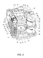
- FIG. 3 shows the media trays of the first media drive 41 and second media drive 51 pulled forward to the media transfer position (the position when the tray is open), and the media tray 45 of the label printer 11 therebelow pulled forward to the media transfer position.
- a space enabling the transportation arm 36 of the media transportation mechanism 31 to move up and down is formed between the pair of right and left side walls 24 and 25 of the one media stacker 21 and between the pair of right and left side walls 27 and 28 of the other media stacker 22 .
- a space is also formed between the top and bottom media stackers 21 and 22 so that the transportation arm 36 of the media transportation mechanism 31 can pivot horizontally for positioning directly above the bottom media stacker 22 .
- both media trays 41 a and 51 a are in the data writing position (when the trays are closed) and the media tray 45 is at the inside printing position, the transportation arm 36 of the media transportation mechanism 31 can descend below the height of the media tray 45 .
- a guide hole through which a disc M released by the transportation arm 36 after descending to this position passes is located below the media transfer position of the printer media tray 45 , and another media stacker described below (a separate media stacker) can be installed in this guide hole 65 .
- This media stacker unit 71 accepts media M guided thereinto by the guide hole 65 , and stores a relatively small number of media M (such as 5 to 10). The media stacker unit 71 accepts the media M from the top and stores the media M stacked coaxially.
- a blank disc M can be picked from the media stacker 22 , the disc can be recorded and printed by one of the media drives 41 and 51 and the label printer 11 , and the disc can then be stored in the media stacker 72 .
- a blank disc M can be removed from the top media stacker 21 or the bottom media stacker 22 , and data can be recorded and a label can be printed by the first media drive 41 or second media drive 51 and the label printer 11 .
- the completed disc can then be stored in the media stacker unit 71 of the drawer tray 70 in the stored (closed) position.
- FIG. 4 is a function block diagram showing the functions of the media processing device.
- FIG. 5 schematically shows the structure of the replaceable units in the media processing device.
- the media processing device 1 has a control unit 80 that controls the other parts of the media processing device, and controls the first media drive drive unit 81 , the second media drive drive unit 82 , the label printer drive unit 83 , and the media transportation mechanism drive unit 84 inside the media processing device 1 .
- the first media drive drive unit 81 controls driving the first media drive 41 according to instructions from the control unit 80 .
- the second media drive drive unit 82 controls driving the label printer 11 according to instructions from the control unit 80 .
- the media transportation mechanism drive unit 84 controls driving the media transportation mechanism 31 according to instructions from the control unit 80 .
- the first media drive 41 or second media drive 51 , the label printer 11 , and the media transportation mechanism 31 are all controlled by a single control unit 80 , but a configuration in which a separate control unit and communication unit are provided for each is also conceivable.
- Volatile memory such as RAM (random access memory) is used as the data storage unit 85 .
- Nonvolatile memory such as EEPROM or flash ROM is used as the nonvolatile storage unit 86 (nonvolatile memory) so that the data can be overwritten.
- the communication unit 88 and the host computer 100 are connected by a dedicated communication line or a general purpose communication line.
- FIG. 5 schematically shows the configuration of the replaceable units 41 , 51 , and 11 in this simplified view of the media processing device.
- the first media drive 41 , the second media drive 51 , and the label printer 11 are used by way of example below as units that can be individually replaced before the service life (that is, the time for which operation can be assured) of the media processing device 1 itself is reached.
- the control unit 80 normally executes a media production operation (a data writing process and a label printing process) based on commands supplied from a host computer 100 .
- a media production operation a data writing process and a label printing process
- the control unit 80 first stores the data in the data storage unit 85 .
- the control unit 80 then controls sequentially driving the media transportation mechanism drive unit 84 and the first media drive drive unit 81 or second media drive drive unit 82 , and picks up a blank disc M from media stacker 21 or 22 shown in FIG. 3 and FIG. 5 .
- the first media drive 41 or second media drive 51 then opens the corresponding media tray 41 a or media tray 51 a to receive the disc M, closes the tray after a disc M is placed thereon (moves the tray to the data writing position), and processes writing the data stored in the data storage unit 85 to the disc M.
- the control unit 80 counts the number of times the media tray 41 a or media tray 51 a opens and closes, identifies the type of media M, and counts the time of the writing process for each media type.
- the media type refers to the type of media for which a different head is used by the media drive, such as CD, DVD, and BD media.
- the control unit 80 controls sequentially driving the first media drive drive unit 81 or second media drive drive unit 82 and the media transportation mechanism drive unit 84 .
- the appropriate media tray (media tray 41 a or media tray 51 a ) is opened, the media M is picked up, the media tray (media tray 41 a or media tray 51 a ) is closed, the disc M is conveyed to and placed on the media tray 45 positioned to the forward media transfer position, and the media tray 45 is then moved to the inside printing position.
- the control unit 80 counts how many times the media tray 41 a or media tray 51 a opens and closes.
- the control unit 80 then controls driving the label printer drive unit 83 , and causes the label printer 11 to print the image data stored in the data storage unit 85 on the label side of the media M. At this time the control unit 80 counts the number of discs printed.
- the control unit 80 has a function for adding the open/close count of each media tray, the data writing time for each media type, and the print count that were counted as described above when controlling driving each drive unit (the first media drive drive unit 81 , second media drive drive unit 82 , label printer drive unit 83 , and media transportation mechanism drive unit 84 ) of the media processing device 1 , and updating the maintenance counter information accordingly.
- control unit 80 writes the total open/close count of the media tray ( 41 a , 51 a ) of the 41 and 51 , the total data writing time of the first media drive 41 and the second media drive 51 for each identified media type, and the total print count of the label printer 11 , to separate storage areas (separate addresses) in the nonvolatile storage unit 86 as described below.
- the total open/close count of the media tray 41 a of the first media drive 41 is written to a first storage area in the nonvolatile storage unit 86 .
- the cumulative DVD writing time (unit: seconds) of the first media drive 41 is written to a fifth storage area in the nonvolatile storage unit 86 .
- the total print count of the label printer 11 is written to a seventh storage area in the nonvolatile storage unit 86 .
- the product serial number is previously written (such as prior to factory shipping) to an eighth storage area in the nonvolatile storage unit 86 .
- each replaceable unit is determined by the life of the individual parts of the replaceable unit. Therefore, when a certain part has reached the end of its service life, the complete replaceable unit must be replaced during maintenance.
- the overall service life of a media drive is generally primarily limited by the life of the data writing head unit (the component including the optical pickup and laser beam generator) used in the media drive. Because lasers of different wavelengths are used to write CD and DVD media, the media drive has plural head units. Because the total write time to CD media and the total write time to DVD media are counted separately, the media drive must be replaced when either head unit reaches the end of its service life based on the time that each head unit is used. Wear of mechanical parts must also be considered when determining the service life of the media drive, and the media drive must also be replaced when the number of times the media tray is opened and closed exceeds the assured open/close count (the upper limit at which durability is assured).
- Replacing the media drive which is a replaceable unit, is therefore necessary when any one of the assured open/close count of the media tray (the upper limit at which durability is assured), the assured CD writing time (the upper limit at which durability is assured), and the assured DVD writing time (the upper limit at which durability is assured), is exceeded.
- the foregoing assured times and counts are values that are preset according to the media processing device 1 , and are stored in a storage unit in the host computer 100 so that they can be referenced by the expected service life value display program.
- FIG. 6 is a flow chart showing the steps in this method of displaying expected service life values for each replacement unit.
- the host computer 100 then receives the maintenance counter information (step S 4 ), and based on the preset assured media tray open/close count, the assured CD writing time, the assured DVD writing time, and the acquired maintenance counter information, calculates the following values A 1 , B 1 , C 1 for the first media drive 41 (step S 5 ).
- a 1 [the total open/close count of the media tray 41 a of the first media drive 41 (from the first storage area)]/[the assured media tray open/close count (the upper limit at which durability is assured)]
- B 1 [the cumulative CD writing time of the first media drive 41 (from the third storage area)]/[the assured CD writing time (the upper limit at which durability is assured)]
- C 1 [the cumulative DVD writing time (unit: seconds) of the first media drive 41 (from the fifth storage area)]/[the assured DVD writing time (the upper limit at which durability is assured)]
- a 2 [the total open/close count of the media tray 51 a of the second media drive 51 (from the second storage area)]/[the assured media tray open/close count (the upper limit at which durability is assured)]
- B 2 [the cumulative CD writing time of the second media drive 51 (from the fourth storage area)]/[the assured CD writing time (the upper limit at which durability is assured)]
- C 2 [the cumulative DVD writing time of the second media drive 51 (from the sixth storage area)]/[the assured DVD writing time (the upper limit at which durability is assured)]
- the user reading the display can easily know approximately how much service life remains until the corresponding unit needs replacing.
- the acquired product serial number of the media processing device 1 (from the eighth storage area) is also displayed on the display unit 101 (step S 10 ).
- the product serial number By displaying the product serial number, which media processing device 1 is connected can be checked when a single host computer 100 is used by reconnecting it to a plurality of media processing devices 1 .
- FIG. 7 shows a sample display of the expected service life values for individual replaceable units of the media processing device.
- the product serial number of the media processing device 1 the total print count of the label printer 11 , the expected service life of the first media drive 41 , and the expected service life of the second media drive 51 are displayed on the display unit 101 .
- the cumulative print count is displayed in this example, but the service life may also be displayed as a percentage equal to the total print count divided by the maximum print count at which printer durability is assured, for example.
- the numeric values of the maintenance counter information displayed as shown in FIG. 7 can also be saved as a file in the host computer by pressing the “save” button, for example. By pressing the “update” button, the maintenance counter information can also be acquired again. The display can also be cleared by pressing the “cancel” button.
- the method of displaying expected service life values according to the invention displays expected service life values compiled for each replaceable unit of the media processing device 1 , such as the expected life of the first media drive 41 , the expected life of the second media drive 51 , and the total print count of the label printer 11 , on a display unit 101 .
- the user can easily know the expected replacement time (expected service life) of each replaceable unit by simply referring to the expected service life values displayed on the display unit 101 .
Abstract
Description
A1=[the total open/close count of the
B1=[the cumulative CD writing time of the first media drive 41 (from the third storage area)]/[the assured CD writing time (the upper limit at which durability is assured)]
C1=[the cumulative DVD writing time (unit: seconds) of the first media drive 41 (from the fifth storage area)]/[the assured DVD writing time (the upper limit at which durability is assured)]
A2=[the total open/close count of the media tray 51a of the second media drive 51 (from the second storage area)]/[the assured media tray open/close count (the upper limit at which durability is assured)]
B2=[the cumulative CD writing time of the second media drive 51 (from the fourth storage area)]/[the assured CD writing time (the upper limit at which durability is assured)]
C2=[the cumulative DVD writing time of the second media drive 51 (from the sixth storage area)]/[the assured DVD writing time (the upper limit at which durability is assured)]
Claims (6)
Applications Claiming Priority (2)
| Application Number | Priority Date | Filing Date | Title |
|---|---|---|---|
| JP2009-042616 | 2009-02-25 | ||
| JP2009042616A JP2010198684A (en) | 2009-02-25 | 2009-02-25 | Method of displaying expected service life values collected by replaceable unit in electronic device, and display program |
Publications (2)
| Publication Number | Publication Date |
|---|---|
| US20100214608A1 US20100214608A1 (en) | 2010-08-26 |
| US8665470B2 true US8665470B2 (en) | 2014-03-04 |
Family
ID=42630726
Family Applications (1)
| Application Number | Title | Priority Date | Filing Date |
|---|---|---|---|
| US12/710,644 Expired - Fee Related US8665470B2 (en) | 2009-02-25 | 2010-02-23 | Method of displaying expected service life values collected by replaceable unit in an electronic device, and a display program |
Country Status (2)
| Country | Link |
|---|---|
| US (1) | US8665470B2 (en) |
| JP (1) | JP2010198684A (en) |
Families Citing this family (3)
| Publication number | Priority date | Publication date | Assignee | Title |
|---|---|---|---|---|
| TWM398178U (en) * | 2010-06-15 | 2011-02-11 | Acard Technology Corp | recording device |
| JP5903949B2 (en) * | 2012-03-14 | 2016-04-13 | セイコーエプソン株式会社 | Control method and control device for media drive |
| JP5768075B2 (en) * | 2013-02-28 | 2015-08-26 | 京セラドキュメントソリューションズ株式会社 | Image forming apparatus |
Citations (15)
| Publication number | Priority date | Publication date | Assignee | Title |
|---|---|---|---|---|
| JPH09259443A (en) | 1996-03-21 | 1997-10-03 | Toshiba Corp | Information processor |
| JPH1196589A (en) | 1997-09-19 | 1999-04-09 | Mitsumi Electric Co Ltd | Optical disk driving device |
| JPH11232835A (en) | 1998-02-13 | 1999-08-27 | Sony Corp | Data management device |
| JP2001101696A (en) | 1999-09-29 | 2001-04-13 | Ricoh Co Ltd | Optical disk device and optical disk system |
| JP2001126369A (en) | 1999-10-27 | 2001-05-11 | Sony Precision Technology Inc | Disk dubbing device and disk changer device |
| JP2002072785A (en) | 2000-08-25 | 2002-03-12 | Canon Inc | Image forming apparatus, cartridge, and life display method for cartridge |
| JP2002187259A (en) | 2000-12-20 | 2002-07-02 | Canon Inc | Recorder |
| JP2004335030A (en) | 2003-05-09 | 2004-11-25 | Funai Electric Co Ltd | Optical disk device |
| JP2005243089A (en) | 2004-02-24 | 2005-09-08 | Sony Corp | Circuit an method for presenting lifetime, and recording and reproducing apparatus |
| JP2006018955A (en) | 2004-07-05 | 2006-01-19 | Hitachi Ltd | Optical disk device and optical disk library device |
| JP2007245501A (en) | 2006-03-15 | 2007-09-27 | Seiko Epson Corp | Printing device, printing information-giving method, and program therefor |
| JP2008097460A (en) | 2006-10-13 | 2008-04-24 | Seiko Epson Corp | Write control method of nonvolatile memory provided in medium processor, medium processor and nonvolatile memory writing system |
| JP2008146768A (en) | 2006-12-12 | 2008-06-26 | Victor Co Of Japan Ltd | Control apparatus |
| JP2009003980A (en) | 2007-06-19 | 2009-01-08 | Seiko Epson Corp | Optical disk conveyance device, conveyance position calculation device, control method and control program of optical disk conveyance device |
| US7607748B2 (en) | 2006-03-15 | 2009-10-27 | Seiko Epson Corporation | Printer |
Family Cites Families (2)
| Publication number | Priority date | Publication date | Assignee | Title |
|---|---|---|---|---|
| JPS5865696U (en) * | 1981-10-27 | 1983-05-04 | 日本電気株式会社 | record player |
| JP2001265538A (en) * | 2000-03-16 | 2001-09-28 | Matsushita Electric Ind Co Ltd | Failure predicting device to predict failure of disk device, medium and information assembly |
-
2009
- 2009-02-25 JP JP2009042616A patent/JP2010198684A/en active Pending
-
2010
- 2010-02-23 US US12/710,644 patent/US8665470B2/en not_active Expired - Fee Related
Patent Citations (17)
| Publication number | Priority date | Publication date | Assignee | Title |
|---|---|---|---|---|
| JPH09259443A (en) | 1996-03-21 | 1997-10-03 | Toshiba Corp | Information processor |
| JPH1196589A (en) | 1997-09-19 | 1999-04-09 | Mitsumi Electric Co Ltd | Optical disk driving device |
| JPH11232835A (en) | 1998-02-13 | 1999-08-27 | Sony Corp | Data management device |
| JP2001101696A (en) | 1999-09-29 | 2001-04-13 | Ricoh Co Ltd | Optical disk device and optical disk system |
| JP2001126369A (en) | 1999-10-27 | 2001-05-11 | Sony Precision Technology Inc | Disk dubbing device and disk changer device |
| JP2002072785A (en) | 2000-08-25 | 2002-03-12 | Canon Inc | Image forming apparatus, cartridge, and life display method for cartridge |
| JP2002187259A (en) | 2000-12-20 | 2002-07-02 | Canon Inc | Recorder |
| JP2004335030A (en) | 2003-05-09 | 2004-11-25 | Funai Electric Co Ltd | Optical disk device |
| JP2005243089A (en) | 2004-02-24 | 2005-09-08 | Sony Corp | Circuit an method for presenting lifetime, and recording and reproducing apparatus |
| JP2006018955A (en) | 2004-07-05 | 2006-01-19 | Hitachi Ltd | Optical disk device and optical disk library device |
| JP2007245501A (en) | 2006-03-15 | 2007-09-27 | Seiko Epson Corp | Printing device, printing information-giving method, and program therefor |
| US7607748B2 (en) | 2006-03-15 | 2009-10-27 | Seiko Epson Corporation | Printer |
| US8147021B2 (en) | 2006-03-15 | 2012-04-03 | Seiko Epson Corporation | Printer |
| US8152263B2 (en) | 2006-03-15 | 2012-04-10 | Seiko Epson Corporation | Printer |
| JP2008097460A (en) | 2006-10-13 | 2008-04-24 | Seiko Epson Corp | Write control method of nonvolatile memory provided in medium processor, medium processor and nonvolatile memory writing system |
| JP2008146768A (en) | 2006-12-12 | 2008-06-26 | Victor Co Of Japan Ltd | Control apparatus |
| JP2009003980A (en) | 2007-06-19 | 2009-01-08 | Seiko Epson Corp | Optical disk conveyance device, conveyance position calculation device, control method and control program of optical disk conveyance device |
Also Published As
| Publication number | Publication date |
|---|---|
| JP2010198684A (en) | 2010-09-09 |
| US20100214608A1 (en) | 2010-08-26 |
Similar Documents
| Publication | Publication Date | Title |
|---|---|---|
| US7974165B2 (en) | Error detection apparatus and method for a disc loading system | |
| JP5477420B2 (en) | Media processing apparatus and method for controlling media processing apparatus | |
| US8665470B2 (en) | Method of displaying expected service life values collected by replaceable unit in an electronic device, and a display program | |
| US8682481B2 (en) | Media processing device, control method for a media processing device, and a control program therefor | |
| TWI391917B (en) | Media processing device and control method for a media processing device | |
| US20130179908A1 (en) | Media processing apparatus and controlling method of the same that prevents processing of the media from being stopped | |
| JP5903949B2 (en) | Control method and control device for media drive | |
| US7712853B2 (en) | Printer-equipped disk recording and/or reproducing apparatus | |
| JP5193528B2 (en) | Media processing apparatus and method for controlling media processing apparatus | |
| US8166493B2 (en) | Media processing device including host computer capable of measuring the height of blank media | |
| JP2008097460A (en) | Write control method of nonvolatile memory provided in medium processor, medium processor and nonvolatile memory writing system | |
| US8376505B2 (en) | Media processing device and a control method and program therefor | |
| JP5223690B2 (en) | Media processing apparatus, control method thereof, and program | |
| US20100079799A1 (en) | Media Processing Device, Control Method for a Media Processing Device, and a Control Program for a Media Processing Device | |
| JP4665870B2 (en) | Method for controlling disk processing apparatus | |
| JP4946654B2 (en) | Media processing apparatus and control method thereof | |
| JP2008234730A (en) | Disk processing device | |
| JP2005158175A (en) | Magnetic tape library device and medium management method therefor | |
| JP5050704B2 (en) | Media processing apparatus and method for controlling media processing apparatus | |
| JP2011159333A (en) | Recording medium processor, control method of recording medium processor, and program | |
| JP2008068571A (en) | Optical disc duplicating apparatus, controlling method and controlling program | |
| JP2013191261A (en) | Medium processor and medium processing system | |
| JP2010165431A (en) | Medium processing system, method of controlling the same, and program | |
| JP2011159253A (en) | Controller, control method, and program | |
| JP2008123632A (en) | Medium processor and its drive control method |
Legal Events
| Date | Code | Title | Description |
|---|---|---|---|
| AS | Assignment |
Owner name: SEIKO EPSON CORPORATION, JAPAN Free format text: ASSIGNMENT OF ASSIGNORS INTEREST;ASSIGNORS:MAESHIMA, HIDETOSHI;YOKOTA, MANABU;REEL/FRAME:023977/0628 Effective date: 20100212 |
|
| STCF | Information on status: patent grant |
Free format text: PATENTED CASE |
|
| FEPP | Fee payment procedure |
Free format text: PAT HOLDER NO LONGER CLAIMS SMALL ENTITY STATUS, ENTITY STATUS SET TO UNDISCOUNTED (ORIGINAL EVENT CODE: STOL); ENTITY STATUS OF PATENT OWNER: LARGE ENTITY |
|
| MAFP | Maintenance fee payment |
Free format text: PAYMENT OF MAINTENANCE FEE, 4TH YEAR, LARGE ENTITY (ORIGINAL EVENT CODE: M1551) Year of fee payment: 4 |
|
| FEPP | Fee payment procedure |
Free format text: MAINTENANCE FEE REMINDER MAILED (ORIGINAL EVENT CODE: REM.); ENTITY STATUS OF PATENT OWNER: LARGE ENTITY |
|
| LAPS | Lapse for failure to pay maintenance fees |
Free format text: PATENT EXPIRED FOR FAILURE TO PAY MAINTENANCE FEES (ORIGINAL EVENT CODE: EXP.); ENTITY STATUS OF PATENT OWNER: LARGE ENTITY |
|
| STCH | Information on status: patent discontinuation |
Free format text: PATENT EXPIRED DUE TO NONPAYMENT OF MAINTENANCE FEES UNDER 37 CFR 1.362 |
|
| FP | Lapsed due to failure to pay maintenance fee |
Effective date: 20220304 |