US8650336B2 - Direct memory access (DMA) device with event mover that moves event from event calendar to expired event queue without management of central processing unit - Google Patents
Direct memory access (DMA) device with event mover that moves event from event calendar to expired event queue without management of central processing unit Download PDFInfo
- Publication number
- US8650336B2 US8650336B2 US11/588,384 US58838406A US8650336B2 US 8650336 B2 US8650336 B2 US 8650336B2 US 58838406 A US58838406 A US 58838406A US 8650336 B2 US8650336 B2 US 8650336B2
- Authority
- US
- United States
- Prior art keywords
- event
- expired
- queue
- descriptor
- calendar
- Prior art date
- Legal status (The legal status is an assumption and is not a legal conclusion. Google has not performed a legal analysis and makes no representation as to the accuracy of the status listed.)
- Expired - Fee Related, expires
Links
Images


Classifications
-
- G—PHYSICS
- G06—COMPUTING OR CALCULATING; COUNTING
- G06F—ELECTRIC DIGITAL DATA PROCESSING
- G06F13/00—Interconnection of, or transfer of information or other signals between, memories, input/output devices or central processing units
- G06F13/14—Handling requests for interconnection or transfer
- G06F13/20—Handling requests for interconnection or transfer for access to input/output bus
- G06F13/28—Handling requests for interconnection or transfer for access to input/output bus using burst mode transfer, e.g. direct memory access DMA, cycle steal
Definitions
- the present invention relates generally to a direct memory access device and more specifically to a direct memory access device based on a timer system.
- Event timers have been implemented in most computing systems. Examples are timers which wait a second for an acknowledgement of a message sent to another computer. Although common, event timers require that the central processing unit (CPU) directly manage the events. As a result, the CPU becomes occupied with monitoring the timing of events. Periodically the event timers interrupt the CPU. High precision with these event timers requires large amounts of CPU time, since the amount of time required for the CPU to handle events is proportional to the precision of the events. Thus, computing systems have been unable to provide high capacity and high precision. Also, many general purpose operating systems have been unable to rapidly switch tasks, making it difficult for the CPU to keep up with events.
- the present invention is directed to a direct memory access device (DMA) that satisfies this need.
- DMA direct memory access device
- a DMA for timing events comprising an event calendar, an expired event queue of a fixed size, a calendar scanner, and an event mover.
- the event calendar stores an event in a linked list.
- the expired event queue stores an event that has already expired from the event calendar.
- the calendar scanner automatically scans the event calendar without management by a CPU.
- the event mover moves an event from the event calendar to the expired event queue without management by the CPU.
- a method of configuring a DMA for timing events comprises storing an event in a linked list using an event calendar, automatically scanning the event calendar using a calendar scanner without management by a CPU, moving the event from the event calendar to an expired event queue of a fixed size using an event mover without management by the CPU, and storing an event that has already expired from the event calendar using the expired event queue.
- a system for timing events comprising a direct memory access device coupled to a CPU.
- the CPU is configured to perform the steps identified in the method described above.
- a computer readable medium on which is stored a set of instructions for timing events. When the instructions are executed, they perform the steps identified in the method described above.
- FIG. 1 is a block diagram of a conventional computer system using a direct memory access device
- FIG. 2 is a block diagram illustrating an overview of the present invention
- FIG. 3 depicts an event calendar according to an exemplary embodiment
- FIG. 4 depicts an event according to an exemplary embodiment
- FIG. 5 depicts an expired event queue according to an exemplary embodiment
- FIG. 6 depicts a flow chart of a method according to an aspect of the present invention.
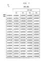
- FIG. 7 depicts a wrap table according to an exemplary embodiment
- FIG. 8 depicts an event being processed according to an exemplary embodiment
- FIG. 9 depicts an expired event queue storing an expired event according to an exemplary embodiment
- FIG. 10 is similar to FIG. 8 but depicting the event further in processing
- FIG. 11 is similar to FIG. 10 but depicting the event further in processing
- FIG. 12 is similar to FIG. 11 but depicting the event further in processing
- FIG. 13 is similar to FIG. 12 but depicting the event further in processing
- FIG. 14 depicts an expired event queue storing an expired event according to an exemplary embodiment
- FIG. 15 is similar to FIG. 13 but depicting the event further in processing
- FIG. 16 is similar to FIG. 15 but depicting the event further in processing
- FIG. 17 is similar to FIG. 16 but depicting the event further in processing
- FIG. 18 depicts a first maintenance descriptor according to an exemplary embodiment
- FIG. 19 depicts a last maintenance descriptor according to an exemplary embodiment.
- FIG. 1 is a block diagram of a conventional computer system using a direct memory access device (DMA) 2 coupled to a central processing unit (CPU) 4 for transferring data from a source memory 6 to a destination memory 8 through a bus 10 .
- DMA direct memory access device
- CPU central processing unit
- source memory 6 and destination memory 8 may be the same physical memory device, in which case DMA 2 could transfer data from one location on the memory device to another location.
- DMA 2 is a piece of computer hardware that is specifically designed to transfer blocks of data from one location in memory to another, independent of the computer's CPU.
- CPU 4 To program DMA 2 , CPU 4 typically programs a source address field, a destination address field, and a length field in bytes on DMA 2 . Together, these parameters are known as a descriptor. Processing a descriptor transfers data, copying a number of bytes having the length specified in the length field, from the address in memory specified as the source address, to the address in memory specified as the destination address. Descriptors are stored in the same memory area as the data to be manipulated on by the DMA.
- next pointer is the address of the following descriptor in a chain of descriptors. Indicating the end of the chain can be done in various ways, such as setting the next pointer or the length field of the last descriptor in the chain to zero.
- a DMA 2 for timing events comprising an event calendar 14 for storing events, an expired event queue 16 of a fixed size for storing events that have already expired from event calendar 14 , a calendar scanner 17 for automatically scanning event calendar 14 without management by CPU 4 , and an event mover 18 for moving the event from event calendar 14 to expired event queue 16 without management by CPU 4 .
- Event calendar 14 is programmed on DMA 2 .
- expired event queue 16 is stored in destination memory 8 .
- FIG. 3 depicts event calendar 14 for storing events, such as event 22 , in a linked list 24 .
- linked list 24 is indexed by time.
- Calendar scanner 17 of FIG. 2 is depicted as a start pointer 32 , a first maintenance descriptor 30 , and a last maintenance descriptor 36 . Calendar scanner 17 may be programmed on DMA 2 .
- Scheduling an event works as follows.
- CPU 4 needs an event to occur sometime in the future, it calculates the required delay for the event.
- the CPU calls a function, referred to as an event handler, to insert the event into event calendar 14 .
- the event handler uses the delay value passed to it and the current time to calculate a time slot in which the event will be scheduled.
- the event handler inserts the event 22 into the linked list 24 associated with time slot 26 , immediately preceding any other events 28 in linked list 24 , so that event 22 is also the first event 22 in linked list 24 .
- the order of events within linked list 24 may be random, or events may be so arranged so that inserting an event is done as efficiently as possible to minimize CPU consumption.
- the event handler also updates an entry in linked list 24 , which is first maintenance descriptor 30 , as detailed further below.
- processing events in a linked list works as follows.
- DMA 2 initiates processing based on an internal periodic timer. If DMA 2 lacks this capability, it can be simulated using software based on the CPU's timers. Such simulation can be efficient on CPU consumption.
- DMA 2 is programmed with a pointer to the first event in the linked list, so as to know where to start processing. DMA 2 processes events, thereby transferring data, and continues along the linked list until it reaches a stop condition. As the timer is periodic, this operation can be programmed to happen at a specific interval.
- DMA 2 refers to its pointer, which is start pointer 32 , to know where to start processing.
- Start pointer 32 points to the first event of the next time slot.
- DMA 2 processes the first event 22 , which instructs DMA 2 to transfer data to expired event queue 16 .
- DMA 2 then processes the next entry in the linked list, transferring more data.
- DMA 2 reaches the two last entries. These two entries maintain the linked list, like start pointer 32 , preparing DMA 2 to process the linked list of the next time slot 34 .
- the before-last entry, first maintenance descriptor 30 points to the first event of the linked list of a next time slot.
- first maintenance descriptor 30 instructs DMA 2 to update start pointer 32 to point to the first event 39 of next time slot 34 .
- DMA 2 then processes the next entry in the linked list, which is last maintenance descriptor 36 .
- Last maintenance descriptor 36 instructs DMA 2 to update first management descriptor 30 of current time slot 26 to point to first maintenance descriptor 38 of next time slot 34 .
- This has the effect of erasing the events that have already expired from the event calendar, namely events, 22 , 28 , and 29 , as well as resetting linked list 24 .
- DMA 2 can reuse linked list 24 or proceed down to next time slot 34 , without CPU intervention.
- last maintenance descriptor 36 instructs DMA 2 to stop processing. Processing starts again when the timer next initiates DMA 2 .
- DMA 2 refers to start pointer 32 , which points to first event 39 of time slot 34 .
- the maximum length of the linked list can be fixed, so that the time required for the DMA to process all events in the linked list does not exceed the duration of the periodic timer. If it exceeds the duration of the timer, precision may be compromised. However, some DMAs cope with this by immediately starting on the next time slot.
- the events in event calendar 14 can be of several types. The least complex would be a simple copy of data from one memory location to another, including a copy from memory to the registers of a device accessible to the CPU. A more complex type could be a message intended for autonomous retransmission, for example due to missing acknowledgements, as required by assured transmission protocols. Again, this too can be implemented as a memory copy. Another complex type is an event which requires software intervention where the event must be stored in a queue such that the software can process it. An extension to this last type is the queuing of event that requires immediate processing, which involves adding the event to a queue and interrupting the software to take immediate action.
- Each type of event in the system may have its own expired event queue with no overhead other than 4 bytes of memory per queue entry.
- Event mover 18 of FIG. 2 is depicted in the following Figures as a queue head pointer, a wrap table for locating the next entry in the expired event queue, and an event comprising a plurality of chained descriptors.
- the wrap table is stored in memory, such as source memory 6 or destination memory 8 .
- each event in event calendar 14 is composed of a chain 80 of six descriptors.
- the first two descriptors namely first descriptor 82 and second descriptor 84 , are responsible for transferring data to expired event queue 16 . Moreover, they form a moving set of descriptors for moving an event that has already expired from the event calendar to the current entry in the expired event queue. Alternatively, a single descriptor may be used to move an event.
- expired event queue 16 has a queue head pointer 102 for indicating the current entry 104 in expired event queue 16 to which an expired event is to be moved.
- expired event queue 16 is of a fixed size, it may be implemented as a pointer to variable sized events.
- queue head pointer 102 must be updated to point to a next entry 106 .
- queue head pointer 102 reaches the bottom of expired event queue 16 , which is a circular list that wraps around from the bottom to the top, queue head pointer 102 must be updated or reset to the top entry of expired event queue 16 , here entry 104 .
- Such wrapping around expired event queue 16 is achieved using memory move operations.
- the other four descriptors are responsible for preparing the DMA for moving events to the next entry in expired event queue 16 .
- these descriptors are third descriptor 86 , fourth descriptor 88 , fifth descriptor 90 , and sixth descriptor 92 (also referred to as first setting descriptor, second setting descriptor, third setting descriptor, and fourth setting descriptor, respectively).
- DMA 2 processes these descriptors, it modifies them with the aid of a wrap table 120 , shown in FIG. 6 , such that queue head pointer 102 wraps around expired event queue 16 and is updated to point to next entry 106 .
- these four descriptors form a configuration set of a plurality of descriptors for updating the queue head, based on the wrap table, to point to the next entry in the expired event queue.
- First descriptor 82 sets a destination field of second descriptor 84 , depicted as “Desc 2 .dest”, to point to current entry 104 in expired event queue 16 to which queue head pointer 102 is pointing, depicted as “&Queuehead”.
- Second descriptor 84 transfers data, depicted as “&Data”, to current entry 104 .
- Third descriptor 86 sets a source field of sixth descriptor 92 to point to current entry 104 to which queue head pointer 102 is pointing.
- Fourth descriptor 88 modifies the source address of fifth descriptor 90 based on current entry 104 to which queue head pointer 102 is pointing.
- Fifth descriptor 90 modifies the source field of sixth descriptor 92 , based on wrap table 120 .
- fifth descriptor 90 modifies the source field of sixth descriptor 92 , based on wrap table 120 , to point to a fourth field 108 in entry 104 of expired event queue 16 , which contains the location of next entry 106 .
- it modifies the source field of sixth descriptor 92 to point to another location in memory, such as a location in source memory 6 or destination memory 8 , which contains the location of next entry 106 .
- Sixth descriptor 92 sets queue head pointer 102 to point to next entry 106 .
- Each descriptor is chained to the next descriptor to be processed.
- DMA 2 would move to the next descriptor, depicted as “NextDesc.scr”, which might be the first descriptor of another event or first maintenance descriptor 30 .
- FIG. 6 depicts a method of configuring a DMA according to another aspect of the present invention.
- an event is stored in linked list 36 using event calendar 14 .
- event calendar 14 is automatically scanned using calendar scanner 17 without management by CPU 4 .
- an event is moved from event calendar 14 to expired event queue 16 using event mover 18 without management by CPU 4 .
- an event that has already expired from the event calendar is stored using expired event queue 16 .
- queue head pointer 102 is initialized.
- the event has as its content a message stored in memory, and that this message is represented by the hexadecimal number 0x0123456789ABCDEF01234567:
- the queue head pointer may be initialized to point to the entry 104 located at the top of expired event queue 16 at address 0xF0000000:
- QueueHead (@0xD0000000): 0xF0000000.
- the expired event queue is initialized as shown in FIG. 5 , so as to have fourth field 108 containing a location of next entries.
- the event may be initalized as shown in FIG. 4 .
- First descriptor 82 sets the destination field of second descriptor 84 to point to the entry in expired event queue 16 to which queue head pointer 102 is pointing, which is current entry 104 . Processing first descriptor 82 results in event 80 shown in FIG. 8 .
- Second descriptor 84 transfers data to current entry 104 . Processing it results in expired event queue 16 , shown storing data in FIG. 9 .
- Expired event queue 16 is of a fixed size, such that wrapping is required when transferring to a next entry, even if the next entry is the last entry.
- wrap table 120 optionally uses fourth field 108 of expired event queue 16 to locate next entry 106 .
- Fourth field 108 may be used for instructing DMA 2 what entry to use next in expired event queue 16 .
- the next entry in expired event queue 16 is at address 0xF0000010.
- Queue head pointer 102 is used to keep track of the entry to which DMA 2 is transferring expired events.
- Third descriptor 86 sets the source field of sixth descriptor 92 to point to current entry 104 to which queue head pointer 102 is pointing. Processing third descriptor 86 results in event 80 shown in FIG. 10 .
- DMA 2 needs instructions on its exact address in memory, which in the present example is the entry to which queue head pointer 102 is pointing plus 0x0C. Since DMA 2 has no adding capabilities, memory move operations are used.
- Wrap table 120 provides a table of pre-calculated answers to the addition problem of the present example. To find the correct entry in wrap table 120 , fourth descriptor 88 modifies the source address of fifth descriptor 90 , which is a location in wrap table 120 , based on current entry 104 to which queue head pointer 102 is pointing. Processing fourth descriptor 88 results in event 80 shown in FIG. 11 .
- Fifth descriptor 90 reads from wrap table 120 and updates the source field of sixth descriptor 92 to point at fourth field 108 of entry 104 , which contains the address of next entry 106 at 0xF0000010. Processing fifth descriptor 90 results in event 80 shown in FIG. 12 .
- processing sixth descriptor 92 updates queue head pointer 102 to point to next entry 106 :
- QueueHead (@0xD0000000): 0xF0000010.
- an event is added to expired event queue 16 without the involvement of CPU 4 .
- expired event queue 16 fills up with expired events and wraps around to the top.
- queue head pointer is at the bottom of expired event queue 16 , pointing to entry 109 at address 0xF0000070:
- QueueHead (@0xD0000000): 0xF0000070.
- next event has a message represented by the hexadecimal number 0x123123121231231212312312:
- Processing first descriptor 82 updates second descriptor 84 to point to the entry to which queue head pointer 102 is pointing, namely the entry located at 0xF0000070, as shown in FIG. 13 .
- Processing second descriptor 84 transfers data to entry 109 , as shown in FIG. 14 .
- entry 109 For simplicity, any events that have been stored in expired event queue 16 between entries 104 and 109 have been omitted.
- Processing third descriptor 86 updates sixth descriptor 92 to point to current entry 109 to which queue head pointer 102 is pointing, as shown in FIG. 15 .
- Processing fourth descriptor 88 updates fifth descriptor 90 , based on current entry 109 to which queue head pointer 102 is pointing, as shown in FIG. 16 .
- Processing fifth descriptor 90 updates sixth descriptor 92 to point at fourth field 108 of entry 109 , located at 0xF000007C, as shown in FIG. 17 .
- processing sixth descriptor 92 updates queue head pointer 102 to point to the next entry whose address is contained at 0xF000007C, which is next entry 104 located at 0xF0000000:
- QueueHead (@0xD0000000): 0xF0000000.
- an expired event can be processed by CPU 4 .
- DMA 2 moves events into expired event queue 16 asynchronously from CPU 4 which reads expired events from expired event queue 16 .
- DMA 2 uses queue head pointer 102 to keep track of its position in expired event queue 16
- CPU 4 uses a tail pointer to keep track of its position in the queue. The tail pointer should not pass queue head pointer 102 .
- CPU 4 reads events from expired event queue 16 , processes them and then increments the tail pointer such that it points to the next event to be processed.
- Expired event queue 16 may be polled periodically for events that it needs to handle. This may be implemented using the software entity that provides the tail pointer.
- the code that is used to handle a particular event could first poll an expired event queue specific to this code, collect all of the events that need to be handled and dispatch all of the events at once. This type of batch processing is much more efficient than processing single events at a time.
- adding an expired event to expired event queue 16 could generate an interrupt, using one or more descriptors, that wakes the software required to process the event.
- low latency event handlers can be constructed that also operate at high capacity.
- first maintenance descriptor 30 is configured as shown in FIG. 18 . It has a source address, which is configured to point to the address of the first descriptor of the first event of the next time slot; a destination address, which points to start pointer 32 ; a length field; and a next field, which points to the address of last maintenance descriptor 36 .
- last maintenance descriptor 36 is configured as shown in FIG. 19 . It may be static, having a source address, which is configured to point to the address of the first maintenance descriptor of the next time slot; a destination address, which points to the source address of the first maintenance descriptor of the current time slot; a length field; and a next field, which is set as a stop condition.
- event calendar 14 stores events in a linked list 24 indexed by time or time slots.
- the events do not, however, need to be indexed by time.
- the events may be controlled by external events and merely indexed by slots, such that external events trigger DMA 2 to proceed from one entry of a slot to another, or from one linked list of a slot to another.
- DMA 2 may support external control by other hardware devices which might be used to initiate the next entry or linked list.
- a static or dynamic event may be implemented by a state machine such that an external piece of hardware would execute commands sent to it by DMA 2 and externally stimulate DMA 2 to proceed with the next entry or linked list.
- a system for timing events comprising DMA 2 coupled to CPU 4 .
- the CPU 4 is configured to perform the steps identified in the method depicted in the flow chart of FIG. 6 .
- CPU 4 writes to memory locations, including those implemented within DMA 2 , so as to control the operation of DMA 2 .
- a computer readable medium on which is stored a set of instructions for timing events, which when executed performs the steps which, again, are identified in the method shown in FIG. 6 .
- the computer readable medium may be stored on a memory storage device, such as a hard disc device, an IC (Integrated Circuit) memory, a magnetic disc device, an optical disc device or the like.
- One of the advantages of the present invention is that it provides general purpose operating systems, such as WindowsTM or LinuxTM, hard real-time capabilities. It also completely eliminates the CPU cost of maintaining a timer system, which may result in a significant performance improvement.
Landscapes
- Engineering & Computer Science (AREA)
- Theoretical Computer Science (AREA)
- Physics & Mathematics (AREA)
- General Engineering & Computer Science (AREA)
- General Physics & Mathematics (AREA)
- Bus Control (AREA)
Abstract
Description
Claims (19)
Priority Applications (1)
| Application Number | Priority Date | Filing Date | Title |
|---|---|---|---|
| US11/588,384 US8650336B2 (en) | 2005-10-28 | 2006-10-27 | Direct memory access (DMA) device with event mover that moves event from event calendar to expired event queue without management of central processing unit |
Applications Claiming Priority (2)
| Application Number | Priority Date | Filing Date | Title |
|---|---|---|---|
| US73134405P | 2005-10-28 | 2005-10-28 | |
| US11/588,384 US8650336B2 (en) | 2005-10-28 | 2006-10-27 | Direct memory access (DMA) device with event mover that moves event from event calendar to expired event queue without management of central processing unit |
Publications (2)
| Publication Number | Publication Date |
|---|---|
| US20070162646A1 US20070162646A1 (en) | 2007-07-12 |
| US8650336B2 true US8650336B2 (en) | 2014-02-11 |
Family
ID=38234053
Family Applications (1)
| Application Number | Title | Priority Date | Filing Date |
|---|---|---|---|
| US11/588,384 Expired - Fee Related US8650336B2 (en) | 2005-10-28 | 2006-10-27 | Direct memory access (DMA) device with event mover that moves event from event calendar to expired event queue without management of central processing unit |
Country Status (1)
| Country | Link |
|---|---|
| US (1) | US8650336B2 (en) |
Families Citing this family (9)
| Publication number | Priority date | Publication date | Assignee | Title |
|---|---|---|---|---|
| US8200699B2 (en) | 2005-12-01 | 2012-06-12 | Microsoft Corporation | Secured and filtered personal information publishing |
| US20080013450A1 (en) * | 2006-04-03 | 2008-01-17 | Worley John S | System and method for time-out management |
| US7870194B2 (en) * | 2006-11-14 | 2011-01-11 | Microsoft Corporation | Sharing calendar information |
| ES2381321T3 (en) * | 2008-01-31 | 2012-05-25 | Telefonaktiebolaget Lm Ericsson (Publ) | Methods and arrangements in a wireless communications system |
| JP5805405B2 (en) * | 2011-02-25 | 2015-11-04 | 京セラ株式会社 | COMMUNICATION DEVICE AND COMMUNICATION DEVICE CONTROL METHOD |
| TWI553476B (en) * | 2015-03-05 | 2016-10-11 | 光寶電子(廣州)有限公司 | Region descriptor management method and electronic apparatus thereof |
| CN106815158A (en) * | 2017-01-17 | 2017-06-09 | 深圳市新威尔电子有限公司 | timing method and device based on Linux system |
| CN112346891B (en) * | 2020-11-26 | 2025-01-14 | 北京京东拓先科技有限公司 | Message storage method, device, equipment and computer readable medium |
| CN112540730B (en) * | 2020-12-14 | 2022-02-08 | 无锡众星微系统技术有限公司 | Dynamically reconfigurable DMA array |
Citations (6)
| Publication number | Priority date | Publication date | Assignee | Title |
|---|---|---|---|---|
| US5982749A (en) * | 1996-03-07 | 1999-11-09 | Lsi Logic Corporation | ATM communication system interconnect/termination unit |
| US20050122962A1 (en) * | 2003-11-10 | 2005-06-09 | Tekelc | Methods and systems for automatic time-based routing rule administration |
| US6981074B2 (en) * | 2003-10-14 | 2005-12-27 | Broadcom Corporation | Descriptor-based load balancing |
| US7039177B1 (en) * | 2000-09-13 | 2006-05-02 | International Business Machines Corp. | Automatic update of a directory entry within a directory of an electronic communication device by electronic notification |
| US7085229B1 (en) * | 2001-10-24 | 2006-08-01 | Cisco Technology, Inc. | Scheduling assist for data networking packet dequeuing in a parallel 1-D systolic array system |
| US7500241B1 (en) * | 2003-10-10 | 2009-03-03 | Avaya Inc. | Method and apparatus for scheduling tasks |
-
2006
- 2006-10-27 US US11/588,384 patent/US8650336B2/en not_active Expired - Fee Related
Patent Citations (6)
| Publication number | Priority date | Publication date | Assignee | Title |
|---|---|---|---|---|
| US5982749A (en) * | 1996-03-07 | 1999-11-09 | Lsi Logic Corporation | ATM communication system interconnect/termination unit |
| US7039177B1 (en) * | 2000-09-13 | 2006-05-02 | International Business Machines Corp. | Automatic update of a directory entry within a directory of an electronic communication device by electronic notification |
| US7085229B1 (en) * | 2001-10-24 | 2006-08-01 | Cisco Technology, Inc. | Scheduling assist for data networking packet dequeuing in a parallel 1-D systolic array system |
| US7500241B1 (en) * | 2003-10-10 | 2009-03-03 | Avaya Inc. | Method and apparatus for scheduling tasks |
| US6981074B2 (en) * | 2003-10-14 | 2005-12-27 | Broadcom Corporation | Descriptor-based load balancing |
| US20050122962A1 (en) * | 2003-11-10 | 2005-06-09 | Tekelc | Methods and systems for automatic time-based routing rule administration |
Also Published As
| Publication number | Publication date |
|---|---|
| US20070162646A1 (en) | 2007-07-12 |
Similar Documents
| Publication | Publication Date | Title |
|---|---|---|
| EP1503292B1 (en) | DMA controller with bus occupation time limitation and sets of DMA parameters for a plurality of logical processors | |
| US7269171B2 (en) | Multi-data receive processing according to a data communication protocol | |
| US20050246461A1 (en) | Scheduling threads in a multi-processor computer | |
| KR970016979A (en) | Queuing system and method of tasks in a multiprocessing system | |
| JP2002541693A5 (en) | ||
| US11341087B2 (en) | Single-chip multi-processor communication | |
| US8650336B2 (en) | Direct memory access (DMA) device with event mover that moves event from event calendar to expired event queue without management of central processing unit | |
| US5287471A (en) | Data transfer controller using direct memory access method | |
| JPS623362A (en) | Data reception system | |
| WO2026021528A1 (en) | Data acceleration processing method and apparatus, chip, device, and readable storage medium | |
| WO2017091963A1 (en) | Information processing method and apparatus | |
| CN119225995A (en) | Inter-core communication method, device, multi-core processor and electronic device | |
| US6920513B2 (en) | Bus management techniques | |
| JPS62172840A (en) | Transferring system for data | |
| EP0614148A1 (en) | Data processing apparatus | |
| US6934770B1 (en) | Method for aborting data transfer commands | |
| JPH05158710A (en) | Timer managing system | |
| JP6940283B2 (en) | DMA transfer control device, DMA transfer control method, and DMA transfer control program | |
| JP2005032036A (en) | Device for automatically setting interruption interval value for channel card | |
| JPH11338712A (en) | Interruption sequence saving circuit | |
| US10140150B2 (en) | Thread diversion awaiting log call return | |
| JPS6049464A (en) | Inter-processor communication system of multi-processor computer | |
| CN120448074A (en) | Data processing method, device, storage medium and product based on execution engine | |
| JPH1124941A (en) | Instruction execution control method and apparatus | |
| JPS63137350A (en) | Execution control system for channel program |
Legal Events
| Date | Code | Title | Description |
|---|---|---|---|
| AS | Assignment |
Owner name: ALCATEL LUCENT, FRANCE Free format text: ASSIGNMENT OF ASSIGNORS INTEREST;ASSIGNORS:MAITLAND, ROGER;IRELAND, HAL;COMBES, ERIC;AND OTHERS;REEL/FRAME:020220/0506;SIGNING DATES FROM 20071023 TO 20071121 Owner name: ALCATEL LUCENT, FRANCE Free format text: ASSIGNMENT OF ASSIGNORS INTEREST;ASSIGNORS:MAITLAND, ROGER;IRELAND, HAL;COMBES, ERIC;AND OTHERS;SIGNING DATES FROM 20071023 TO 20071121;REEL/FRAME:020220/0506 |
|
| AS | Assignment |
Owner name: CREDIT SUISSE AG, NEW YORK Free format text: SECURITY AGREEMENT;ASSIGNOR:LUCENT, ALCATEL;REEL/FRAME:029821/0001 Effective date: 20130130 Owner name: CREDIT SUISSE AG, NEW YORK Free format text: SECURITY AGREEMENT;ASSIGNOR:ALCATEL LUCENT;REEL/FRAME:029821/0001 Effective date: 20130130 |
|
| FEPP | Fee payment procedure |
Free format text: PAYOR NUMBER ASSIGNED (ORIGINAL EVENT CODE: ASPN); ENTITY STATUS OF PATENT OWNER: LARGE ENTITY |
|
| STCF | Information on status: patent grant |
Free format text: PATENTED CASE |
|
| AS | Assignment |
Owner name: ALCATEL LUCENT, FRANCE Free format text: RELEASE BY SECURED PARTY;ASSIGNOR:CREDIT SUISSE AG;REEL/FRAME:033868/0555 Effective date: 20140819 |
|
| FPAY | Fee payment |
Year of fee payment: 4 |
|
| AS | Assignment |
Owner name: PROVENANCE ASSET GROUP LLC, CONNECTICUT Free format text: ASSIGNMENT OF ASSIGNORS INTEREST;ASSIGNORS:NOKIA TECHNOLOGIES OY;NOKIA SOLUTIONS AND NETWORKS BV;ALCATEL LUCENT SAS;REEL/FRAME:043877/0001 Effective date: 20170912 Owner name: NOKIA USA INC., CALIFORNIA Free format text: SECURITY INTEREST;ASSIGNORS:PROVENANCE ASSET GROUP HOLDINGS, LLC;PROVENANCE ASSET GROUP LLC;REEL/FRAME:043879/0001 Effective date: 20170913 Owner name: CORTLAND CAPITAL MARKET SERVICES, LLC, ILLINOIS Free format text: SECURITY INTEREST;ASSIGNORS:PROVENANCE ASSET GROUP HOLDINGS, LLC;PROVENANCE ASSET GROUP, LLC;REEL/FRAME:043967/0001 Effective date: 20170913 |
|
| AS | Assignment |
Owner name: NOKIA US HOLDINGS INC., NEW JERSEY Free format text: ASSIGNMENT AND ASSUMPTION AGREEMENT;ASSIGNOR:NOKIA USA INC.;REEL/FRAME:048370/0682 Effective date: 20181220 |
|
| MAFP | Maintenance fee payment |
Free format text: PAYMENT OF MAINTENANCE FEE, 8TH YEAR, LARGE ENTITY (ORIGINAL EVENT CODE: M1552); ENTITY STATUS OF PATENT OWNER: LARGE ENTITY Year of fee payment: 8 |
|
| AS | Assignment |
Owner name: PROVENANCE ASSET GROUP LLC, CONNECTICUT Free format text: RELEASE BY SECURED PARTY;ASSIGNOR:CORTLAND CAPITAL MARKETS SERVICES LLC;REEL/FRAME:058983/0104 Effective date: 20211101 Owner name: PROVENANCE ASSET GROUP HOLDINGS LLC, CONNECTICUT Free format text: RELEASE BY SECURED PARTY;ASSIGNOR:CORTLAND CAPITAL MARKETS SERVICES LLC;REEL/FRAME:058983/0104 Effective date: 20211101 Owner name: PROVENANCE ASSET GROUP LLC, CONNECTICUT Free format text: RELEASE BY SECURED PARTY;ASSIGNOR:NOKIA US HOLDINGS INC.;REEL/FRAME:058363/0723 Effective date: 20211129 Owner name: PROVENANCE ASSET GROUP HOLDINGS LLC, CONNECTICUT Free format text: RELEASE BY SECURED PARTY;ASSIGNOR:NOKIA US HOLDINGS INC.;REEL/FRAME:058363/0723 Effective date: 20211129 Owner name: PROVENANCE ASSET GROUP HOLDINGS LLC, CONNECTICUT Free format text: RELEASE OF SECURITY INTEREST;ASSIGNOR:CORTLAND CAPITAL MARKETS SERVICES LLC;REEL/FRAME:058983/0104 Effective date: 20211101 Owner name: PROVENANCE ASSET GROUP LLC, CONNECTICUT Free format text: RELEASE OF SECURITY INTEREST;ASSIGNOR:CORTLAND CAPITAL MARKETS SERVICES LLC;REEL/FRAME:058983/0104 Effective date: 20211101 Owner name: PROVENANCE ASSET GROUP HOLDINGS LLC, CONNECTICUT Free format text: RELEASE OF SECURITY INTEREST;ASSIGNOR:NOKIA US HOLDINGS INC.;REEL/FRAME:058363/0723 Effective date: 20211129 Owner name: PROVENANCE ASSET GROUP LLC, CONNECTICUT Free format text: RELEASE OF SECURITY INTEREST;ASSIGNOR:NOKIA US HOLDINGS INC.;REEL/FRAME:058363/0723 Effective date: 20211129 |
|
| AS | Assignment |
Owner name: RPX CORPORATION, CALIFORNIA Free format text: ASSIGNMENT OF ASSIGNORS INTEREST;ASSIGNOR:PROVENANCE ASSET GROUP LLC;REEL/FRAME:059352/0001 Effective date: 20211129 |
|
| AS | Assignment |
Owner name: BARINGS FINANCE LLC, AS COLLATERAL AGENT, NORTH CAROLINA Free format text: PATENT SECURITY AGREEMENT;ASSIGNOR:RPX CORPORATION;REEL/FRAME:063429/0001 Effective date: 20220107 |
|
| AS | Assignment |
Owner name: RPX CORPORATION, CALIFORNIA Free format text: RELEASE OF LIEN ON PATENTS;ASSIGNOR:BARINGS FINANCE LLC;REEL/FRAME:068328/0278 Effective date: 20240802 |
|
| AS | Assignment |
Owner name: BARINGS FINANCE LLC, AS COLLATERAL AGENT, NORTH CAROLINA Free format text: PATENT SECURITY AGREEMENT;ASSIGNORS:RPX CORPORATION;RPX CLEARINGHOUSE LLC;REEL/FRAME:068328/0674 Effective date: 20240802 |
|
| FEPP | Fee payment procedure |
Free format text: MAINTENANCE FEE REMINDER MAILED (ORIGINAL EVENT CODE: REM.); ENTITY STATUS OF PATENT OWNER: LARGE ENTITY |
|
| LAPS | Lapse for failure to pay maintenance fees |
Free format text: PATENT EXPIRED FOR FAILURE TO PAY MAINTENANCE FEES (ORIGINAL EVENT CODE: EXP.); ENTITY STATUS OF PATENT OWNER: LARGE ENTITY |
|
| STCH | Information on status: patent discontinuation |
Free format text: PATENT EXPIRED DUE TO NONPAYMENT OF MAINTENANCE FEES UNDER 37 CFR 1.362 |
|
| FP | Lapsed due to failure to pay maintenance fee |
Effective date: 20260211 |