US8628458B2 - Three-phase separator having an overflow outlet for one phase and a centripetal pump for another phase - Google Patents
Three-phase separator having an overflow outlet for one phase and a centripetal pump for another phase Download PDFInfo
- Publication number
- US8628458B2 US8628458B2 US12/667,246 US66724608A US8628458B2 US 8628458 B2 US8628458 B2 US 8628458B2 US 66724608 A US66724608 A US 66724608A US 8628458 B2 US8628458 B2 US 8628458B2
- Authority
- US
- United States
- Prior art keywords
- separator
- drum
- phase
- fluid
- heavy phase
- Prior art date
- Legal status (The legal status is an assumption and is not a legal conclusion. Google has not performed a legal analysis and makes no representation as to the accuracy of the status listed.)
- Expired - Fee Related, expires
Links
Images


Classifications
-
- B—PERFORMING OPERATIONS; TRANSPORTING
- B04—CENTRIFUGAL APPARATUS OR MACHINES FOR CARRYING-OUT PHYSICAL OR CHEMICAL PROCESSES
- B04B—CENTRIFUGES
- B04B1/00—Centrifuges with rotary bowls provided with solid jackets for separating predominantly liquid mixtures with or without solid particles
- B04B1/04—Centrifuges with rotary bowls provided with solid jackets for separating predominantly liquid mixtures with or without solid particles with inserted separating walls
- B04B1/08—Centrifuges with rotary bowls provided with solid jackets for separating predominantly liquid mixtures with or without solid particles with inserted separating walls of conical shape
-
- B—PERFORMING OPERATIONS; TRANSPORTING
- B04—CENTRIFUGAL APPARATUS OR MACHINES FOR CARRYING-OUT PHYSICAL OR CHEMICAL PROCESSES
- B04B—CENTRIFUGES
- B04B1/00—Centrifuges with rotary bowls provided with solid jackets for separating predominantly liquid mixtures with or without solid particles
- B04B1/10—Centrifuges with rotary bowls provided with solid jackets for separating predominantly liquid mixtures with or without solid particles with discharging outlets in the plane of the maximum diameter of the bowl
- B04B1/12—Centrifuges with rotary bowls provided with solid jackets for separating predominantly liquid mixtures with or without solid particles with discharging outlets in the plane of the maximum diameter of the bowl with continuous discharge
-
- B—PERFORMING OPERATIONS; TRANSPORTING
- B04—CENTRIFUGAL APPARATUS OR MACHINES FOR CARRYING-OUT PHYSICAL OR CHEMICAL PROCESSES
- B04B—CENTRIFUGES
- B04B1/00—Centrifuges with rotary bowls provided with solid jackets for separating predominantly liquid mixtures with or without solid particles
- B04B1/10—Centrifuges with rotary bowls provided with solid jackets for separating predominantly liquid mixtures with or without solid particles with discharging outlets in the plane of the maximum diameter of the bowl
- B04B1/14—Centrifuges with rotary bowls provided with solid jackets for separating predominantly liquid mixtures with or without solid particles with discharging outlets in the plane of the maximum diameter of the bowl with periodical discharge
-
- B—PERFORMING OPERATIONS; TRANSPORTING
- B04—CENTRIFUGAL APPARATUS OR MACHINES FOR CARRYING-OUT PHYSICAL OR CHEMICAL PROCESSES
- B04B—CENTRIFUGES
- B04B11/00—Feeding, charging, or discharging bowls
- B04B11/02—Continuous feeding or discharging; Control arrangements therefor
-
- B—PERFORMING OPERATIONS; TRANSPORTING
- B04—CENTRIFUGAL APPARATUS OR MACHINES FOR CARRYING-OUT PHYSICAL OR CHEMICAL PROCESSES
- B04B—CENTRIFUGES
- B04B11/00—Feeding, charging, or discharging bowls
- B04B11/08—Skimmers or scrapers for discharging ; Regulating thereof
- B04B11/082—Skimmers for discharging liquid
-
- B—PERFORMING OPERATIONS; TRANSPORTING
- B04—CENTRIFUGAL APPARATUS OR MACHINES FOR CARRYING-OUT PHYSICAL OR CHEMICAL PROCESSES
- B04B—CENTRIFUGES
- B04B13/00—Control arrangements specially designed for centrifuges; Programme control of centrifuges
- B04B2013/006—Interface detection or monitoring of separated components
Definitions
- the present disclosure relates to a separator including a single or double conical drum rotatably mounted on one of its axial ends about a vertical axis of rotation.
- FIG. 3 A known three-phase separator is illustrated in FIG. 3 .
- a centripetal pump is assigned to one or both of the two fluid discharges or outlets from the drum and the additional outlet is constructed in a nozzle-type manner, a delta LP area is formed, within which the centripetal pump permits a displacement of the separation zone in the drum by throttling.
- International Patent Document WO 86/01436 Here the area of displaceability of the separation zone is still relatively small, and it is also not easily possible to displace the separation zone in the area sufficiently rapidly. The displacement also does not always lead to stable process conditions because the variation of the throttling of the centripetal pump outlets will influence several parameters of the process simultaneously.
- U.S. Pat. No. 4,417,885 A Japanese Patent Document JP 03 13 54 58 A, and German Patent Documents DE 1 140 144 and DE 23 22 491 A1 are noted.
- U.S. Pat. No. 4,417,885 A shows a fluid seal on a centripetal-pump-type outlet of a separator.
- International Patent Documents WO 2006/096113 and WO 92/07658 also suggest the feeding of pressure in the inlet area of a centrifuge.
- Another three-phase separator is known from German Patent Document DE 10 2005 021 331.6.
- This document suggests a separator having a separator drum, which has an inlet tube for a product to be processed, at least two fluid outlets for a lighter phase and a heavier phase, solid material discharge openings, preferably in the area of its largest inner circumference, a separation pan assembly arranged in the separator drum and an adjustable throttling device outside the drum.
- the adjustable throttling device has a ring plate or orifice plate and is designed for displacing the fluid radius, to which the heavy phase extends in the drum, by changing the outflow cross-section for the heavy fluid phase by throttling. This construction was found to be successful, but a further constructive simplification is desirable.
- the present disclosure relates to a further development of a separator of the above-mentioned type such that, in a constructively simple manner, it is possible to displace the separation zone within the drum over a sufficiently large radial area during the operation. In such a case, a good adjustability of the location of the separation zone is possible.
- the present disclosure relates to a separator that includes a separator drum having a conical interior and rotatably mounted at an axial end about a vertical axis of rotation.
- a rotating spindle located at either a lower or upper end of the separator drum and is configured to drive the separator drum.
- the rotating spindle is disposed in an oscillating manner about a hinge point.
- a supply tube for a product to be processed and at least two fluid outlets.
- One fluid outlet is for a light phase and one fluid outlet for a heavy phase.
- a solid material discharge opening is located in an area of the separator drum's largest inner circumference.
- a separation pan assembly and a pressure chamber configured to be acted upon by a fluid to change a location of a separation zone between the light phase and the heavy phase.
- the pressure may decrease in the center, whereby pressures P 1 and P 2 are lowered.
- the pressures P 1 and P 2 as well as the process temperature, the one or both fluid phase(s) may start to evaporate or boil. This may prevent a good separation because gas bubbles or foam may form in the fluid.
- carbon dioxide may also evolve, which may result in an increase of the pH value in the crude oil and may lead to the formation of calcium naphthenates and other compounds. This may have a very disadvantageous effect on the process stability in the drum.
- the steam pressure of the two fluids may differ, which, because of the difference of the chamber pressures P 1 and P 2 , may result in a displacement of the E-line.
- Maintaining pressure on the fluid phases, which is higher than the steam pressure of the corresponding fluids may avoid these disadvantageous effects and may also be utilized for controlling. For example, automatically controlling the location of the E-line by varying the differential pressure between P 1 and P 2 .
- the present disclosure also relates to a process in which, by a separator according to the present disclosure, the work takes place according to a step that includes maintaining a pressure on the fluid phases which is higher than the steam pressure of the corresponding fluids.
- the separator is extremely suitable for the most varied three-phase separating tasks. For example, it is suitable for processing crude oil, in which the crude oil is cleansed from solid material and water and is separated from the crude oil. It is also suitable for the treatment of diluted soluble oil, by which water is separated from oil and cleansed from solid material.
- the fluid outlet for the lighter phase (LP) is provided with a centripetal pump.
- the fluid outlet for the heavier phase (HP) may also be provided with a centripetal pump but a centripetal pump is not provided in the embodiment as depicted in FIG. 1 .
- the pressure chamber may be arranged in front of one of the fluid outlets or both fluid outlets.
- One of the pressure chambers or the one pressure chamber may, however also be constructed in the area of an inlet chamber.
- FIG. 1 is a sectional view of one half of a separator drum, according to the present disclosure
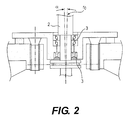
- FIG. 2 is a sectional view of an embodiment showing a drive area for the separator drum FIG. 1 .
- FIG. 3 is a sectional view of one half of a separator drum, according to the state of the art.
- FIGS. 1 and 3 each illustrate a separator drum 1 having a vertically oriented axis of rotation at the radius r 0 .
- the separator drums 1 are each placed on a rotating spindle 2 which is driven, for example, as illustrated in FIG. 2 , directly or by way of a belt (not shown) or in a different manner, for example, by way of a gearing.
- the rotating spindle 2 may have a conical development.
- the rotating spindle 2 is disposed on one side of the drum 1 for example, below the drum, in an oscillating manner.
- the oscillating operation therefore, describes or sets a new axis, differently than in the case of a decanter, as a result of residual unbalances which describe a type of precession movement about the vertical line r 0 , as shown, for example, in FIG. 2 , in which the angle of inclination ⁇ is illustrated.
- constructions are also known in which a lower drum is quasi “suspended” at the upper rotating spindle 2 .
- the drum 1 is rotatably disposed in an oscillating manner only at one of its ends or connected to one of its axial ends.
- the separator drum 1 has a supply tube 4 for a product P to be centrifuged, a distributor 5 adjoining this supply tube 4 and being provided with at least one or more outlet openings 6 through which inflowing centrifugal product, shown as crosshatching, can be guided into the interior of the separator drum 1 and the rising duct 7 of the separation pan assembly 8 .
- a feeding through the spindle 2 is also within the scope of the present disclosure.
- the construction of the separator drum 1 is selected such that the outlet openings 6 are situated below the rising duct 7 in the separation pan assembly 8 including conically shaped separation pans. In the upward direction, the separation pan assembly 8 is closed off by a separation pan 10 having a larger diameter than the separation pan assembly 8 .
- a separation zone between a light or lighter fluid phase LP and a heavy or heavier fluid phase HP is foamed within the separation pan assembly 8 . This occurs within the rising duct 7 during an operation in the case of a corresponding rotation of the drum 1 at a certain radius r E or the emulsion line or separation zone or separating line, which is also called E-line.
- the lighter fluid phase LP is guided out of the drum 1 at an inside radius r LP by a centripetal pump 11 , which may also be called a gripper. With the aid of the back pressure created by the rotational energy of the fluid, the centripetal pump 11 operates like a pump.
- a valve for throttling is connected behind the centripetal pump 11 , for example, outside the separator drum 1 , in a discharge connected on an output side.
- the heavy fluid phase HP flows around the outer circumference of the separation pan 10 through a discharge duct 12 to a fluid outlet at the upper axial end of the drum 1 at, for example, r HP , which is further developed as overflow outlet 13 at the radius r HP , as shown in FIG. 3 .
- the heavy phase HP flows out of the drum at the overflow outlet 13 .
- FIGS. 1 and 3 correspond to one another to this extent. They can also be provided with the same driving devices.
- constructions according to the present disclosure at, for example, that of FIG. 1 in contrast, to that of FIG. 3 , is provided with a device, which during the operation, permits a reacting to changing properties of the product to be processed.
- the overflow outlet 13 for the heavy phase HP is situated on the radius r HD at the upper axial end of the separator drum 1 .
- a baffle plate 14 is arranged toward the drum interior axially in front of the overflow 13 , which baffle plate 14 extends from the interior toward the outside and its largest radius r 14 is larger than the radius r HD , so that the heavy phase HP has to flow on the outside around the baffle plate 14 before exiting out of the overflow outlet 13 .
- the centripetal chamber 9 around the centripetal pump 11 is, in addition, bounded axially upward and downward by two blocking disks 15 , 16 , respectively, which extend radially from the outside toward the inside to the radii r 15 and r 16 , which are smaller than the outer radius r 11 of the centripetal pump 11 as measured axially from the inside to outside.
- the centripetal pump 11 projects, by its centripetal pump section with its inlet openings, to a radius r 11 which is larger than the inner radius of the blocking disks 15 , 16 .
- a pressure chamber 17 is constructed, and a feeding pipe 18 leads into the pressure chamber 17 .
- the pressure chamber 17 can be acted upon by a fluid, particularly a gas, through the feeding pipe 18 having a valve 19 connected on the input side.
- a variation of the fluid pressure in the pressure chamber 17 results in a displacing of the fluid level at R H1 of the heavy phase HP in the pressure chamber 17 between the inner radius r 15 and the outer radius r 14 and in a displacing of the fluid levels of the light phase LP above and below the centripetal pump 11 in the centripetal chamber 9 .
- the displacing of the fluid level takes place because otherwise a flooding of the pressure chamber 17 would occur.
- the displacing of the fluid level needs to be at no less than radius r L2 because that would displace the E-line or r E into the center of the drum 1 so that no more space would remain for the light phase LP.
- the double-cone drum 1 has a solid material discharge nozzle 20 in the area of its largest diameter, which nozzle 20 is used for the continuous discharge of solid particles S from the drum 1 .
- nozzle 20 is used for the continuous discharge of solid particles S from the drum 1 .
- embodiments with and without additional solid material discharges or with a discontinuous discharge, for example, by a piston slide valve, are also within the scope of the present disclosure.
- the pressure chamber 17 offers a possibility for adjusting and controlling the location of the emulsion line, or E-line, and leads to a better mastering and controlling of the process. This also results in an enlarged adjusting range of the separation zone r E .
Landscapes
- Centrifugal Separators (AREA)
Applications Claiming Priority (4)
| Application Number | Priority Date | Filing Date | Title |
|---|---|---|---|
| DE202007009212U DE202007009212U1 (de) | 2007-06-30 | 2007-06-30 | Drei-Phasen-Trennseparator |
| DE20-2007-009-212.1 | 2007-06-30 | ||
| DE202007009212 | 2007-06-30 | ||
| PCT/EP2008/005240 WO2009003639A1 (de) | 2007-06-30 | 2008-06-27 | Drei-phasen-trennseparator |
Publications (2)
| Publication Number | Publication Date |
|---|---|
| US20100184579A1 US20100184579A1 (en) | 2010-07-22 |
| US8628458B2 true US8628458B2 (en) | 2014-01-14 |
Family
ID=38473084
Family Applications (1)
| Application Number | Title | Priority Date | Filing Date |
|---|---|---|---|
| US12/667,246 Expired - Fee Related US8628458B2 (en) | 2007-06-30 | 2008-06-27 | Three-phase separator having an overflow outlet for one phase and a centripetal pump for another phase |
Country Status (9)
| Country | Link |
|---|---|
| US (1) | US8628458B2 (de) |
| EP (1) | EP2162225A1 (de) |
| CN (1) | CN101687204B (de) |
| AU (1) | AU2008271581B2 (de) |
| BR (1) | BRPI0813784A2 (de) |
| CA (1) | CA2691931C (de) |
| DE (1) | DE202007009212U1 (de) |
| RU (1) | RU2465052C2 (de) |
| WO (1) | WO2009003639A1 (de) |
Cited By (6)
| Publication number | Priority date | Publication date | Assignee | Title |
|---|---|---|---|---|
| US20150149098A1 (en) * | 2013-11-12 | 2015-05-28 | SYNCRUDE CANADA LTD. in trust for the owners of the Syncrude Project, as such owners exist now and | Method of detecting and controlling e-line loss |
| RU183814U1 (ru) * | 2018-01-10 | 2018-10-03 | Федеральное государственное бюджетное образовательное учреждение высшего образования "Саратовский государственный технический университет имени Гагарина Ю.А." (СГТУ имени Гагарина Ю.А.) | Биконическая центрифуга |
| RU183954U1 (ru) * | 2018-01-10 | 2018-10-10 | Федеральное государственное бюджетное образовательное учреждение высшего образования "Саратовский государственный технический университет имени Гагарина Ю.А." (СГТУ имени Гагарина Ю.А.) | Гидроциклон с двойным входом |
| US10384216B1 (en) * | 2008-04-22 | 2019-08-20 | Pneumatic Scale Corporation | Centrifuge system including a control circuit that controls positive back pressure within the centrifuge core |
| US10895141B2 (en) | 2018-01-11 | 2021-01-19 | Encline Artificial Lift Technologies LLC | Controlled high pressure separator for production fluids |
| RU204277U1 (ru) * | 2020-09-30 | 2021-05-18 | Федеральное государственное бюджетное образовательное учреждение высшего образования "Саратовский государственный технический университет имени Гагарина Ю.А." (СГТУ имени Гагарина Ю.А.) | Биконический гидроциклон с улучшенной конструкцией отводящих патрубков осветленной жидкости |
Families Citing this family (13)
| Publication number | Priority date | Publication date | Assignee | Title |
|---|---|---|---|---|
| WO2007131515A1 (de) * | 2006-05-11 | 2007-11-22 | Westfalia Separator Ag | Drei-phasen-trennseparator mit einer schälscheibe und feststoffaustragsöffnungen |
| WO2008058340A1 (en) * | 2006-11-15 | 2008-05-22 | Westfalia Separator Australia Pty Ltd | Continuous self-cleaning centrifuge assembly |
| DE202007009212U1 (de) * | 2007-06-30 | 2008-12-11 | Gea Westfalia Separator Gmbh | Drei-Phasen-Trennseparator |
| SE535959C2 (sv) * | 2010-01-29 | 2013-03-05 | Alfa Laval Corp Ab | System innefattande centrifugalseparator samt metod för kontroll av detsamma |
| DK2366457T3 (da) * | 2010-03-19 | 2013-06-10 | Alfa Laval Corp Ab | Anordning og fremgangsmåde til monitorering og justering af et grænsefladelags radiale position i en centrifuge |
| MX2013000973A (es) | 2010-07-30 | 2013-03-07 | Gea Mechanical Equipment Gmbh | Un separador que tiene un tambor centrifugo. |
| DE102010038195A1 (de) * | 2010-10-14 | 2012-04-19 | Gea Mechanical Equipment Gmbh | Verfahren zur Phasentrennung eines Produktes mit einer Zentrifuge |
| DE102013111576A1 (de) * | 2013-10-21 | 2015-04-23 | Gea Mechanical Equipment Gmbh | Verfahren zur Klärung eines fließfähigen Produktes mit einer Zentrifuge, insbesondere einem Separator |
| DE102013111579A1 (de) * | 2013-10-21 | 2015-04-23 | Gea Mechanical Equipment Gmbh | Verfahren zur Klärung eines fließfähigen Produktes mit einer Zentrifuge, insbesondere einem Separator |
| EP3085449B1 (de) * | 2015-04-24 | 2020-06-03 | Alfa Laval Corporate AB | Zentrifugalabscheider und zugehörige verfahren |
| BR102015028129B1 (pt) * | 2015-11-09 | 2021-11-03 | Delp Engenharia Mecânica S.A. | Separador centrífugo |
| CN108176520A (zh) * | 2017-12-25 | 2018-06-19 | 江苏巨能机械有限公司 | 三相碟式分离机 |
| EP3865218A1 (de) * | 2020-02-11 | 2021-08-18 | GEA Mechanical Equipment GmbH | Verfahren zum betrieb einer zentrifuge und eine anordnung umfassend eine zentrifuge und ein gasreservoir |
Citations (32)
| Publication number | Priority date | Publication date | Assignee | Title |
|---|---|---|---|---|
| DE1140144B (de) | 1960-08-19 | 1962-11-22 | Westfalia Separator Ag | Schleudertrommel mit Zufuehrungskanaelen fuer Spuel- oder Verduennungsfluessigkeit |
| US3408000A (en) * | 1965-08-23 | 1968-10-29 | Alfa Laval Ab | Determination of sludge level in sludge centrifuge |
| US3445061A (en) * | 1966-11-14 | 1969-05-20 | Alfa Laval Ab | Apparatus for indicating sludge level in centrifuges |
| US3563453A (en) * | 1968-02-23 | 1971-02-16 | Alfa Laval Ab | Method and apparatus for indicating sludge level in sludge centrifuge |
| US3580493A (en) * | 1967-10-31 | 1971-05-25 | Alfa Laval Ab | Method and apparatus for detecting sludge level in a centrifuge |
| US3601307A (en) * | 1970-03-19 | 1971-08-24 | Pennwalt Corp | Centrifuge with spindle-sealing means |
| US3637134A (en) * | 1970-01-21 | 1972-01-25 | Laval Separator Co De | Apparatus for indicating the sludge level in centrifuges |
| US3642196A (en) * | 1969-05-08 | 1972-02-15 | Alfa Laval Ab | Centrifuge with sludge level sensing means |
| US3750940A (en) * | 1970-12-07 | 1973-08-07 | Alfa Laval Ab | Control means for self-discharging centrifuge |
| US3752389A (en) * | 1970-12-07 | 1973-08-14 | Alfa Laval Ab | Centrifugal separator with control means |
| US3976242A (en) * | 1974-07-27 | 1976-08-24 | Westfalia Separator Aktiengesellschaft | Self-emptying clarifying separator having a foam-free removal of the clarified liquid by means of a paring disk and an automatically operating system for detecting the level of the solids in the sludge chamber |
| US3990632A (en) * | 1975-02-06 | 1976-11-09 | Westfalia Separator Ag | Self-cleaning centrifugal separator with automatic control |
| US4193537A (en) * | 1977-11-01 | 1980-03-18 | Alfa-Laval Ab | Centrifugal separator with presedimentation means |
| US4305817A (en) * | 1979-06-29 | 1981-12-15 | Westfalia Separator Ag | Self-emptying clarifying drum |
| US4343431A (en) * | 1979-09-05 | 1982-08-10 | Alfa-Laval Ab | Centrifugal separator |
| US4417885A (en) * | 1981-10-22 | 1983-11-29 | Westfalia Separator Ag | Centrifuge with vertical axis of rotation |
| US4525155A (en) * | 1983-04-20 | 1985-06-25 | Alfa-Laval Marine And Powering Engineering Ab | Centrifugal separator and method of operating the same |
| WO1986001436A1 (en) | 1984-08-28 | 1986-03-13 | Alfa-Laval Zeta A/S | A method of controlling the interface between oil and water during discharge of sludge from a centrifuge for separation of oil and water and sludge |
| US4755165A (en) * | 1986-01-22 | 1988-07-05 | Westfalia Separator Ag | Method and device for separating two liquid phases by means of a centrifuge |
| DE3806742A1 (de) * | 1987-03-19 | 1988-10-06 | Alfa Laval Separation Ab | Zentrifuge mit verbesserter auslassanordnung |
| US4820256A (en) * | 1985-06-07 | 1989-04-11 | Alfa-Laval Separation Ab | Centrifugal separator |
| US5104371A (en) * | 1987-10-15 | 1992-04-14 | Alfa-Laval Marine & Power Engineering Ab | Cleaning of a centrifugal separator |
| WO1992007658A1 (en) | 1990-10-29 | 1992-05-14 | Alfa-Laval Separation Ab | Centrifugal separator with receiving chamber for additional liquid |
| US5788622A (en) * | 1996-01-29 | 1998-08-04 | Alfa-Laval Ab | Outlet device and a centrifugal separator provided with such an outlet device |
| US6837842B1 (en) * | 1999-03-08 | 2005-01-04 | Alfa Laval Ab | Method and device for indicating an undesired operation condition of a centrifugal separator |
| US6976948B1 (en) * | 1999-06-03 | 2005-12-20 | Alfa Laval Ab | Method for adjusting a radial level of an interface in a centrifugal separator |
| WO2006096113A1 (en) | 2005-03-08 | 2006-09-14 | Alfa Laval Corporate Ab | A centrifugal separator |
| DE102005021331A1 (de) | 2005-05-04 | 2006-11-09 | Westfalia Separator Ag | Drei-Phasen-Trennseparator mit einer Schälscheibe und Feststoffaustragsöffnungen |
| US20090298666A1 (en) * | 2006-05-11 | 2009-12-03 | Westfalia Separator Ag | Three Phase Separator |
| US7678039B2 (en) * | 2006-02-13 | 2010-03-16 | Alfa Laval Corporate Ab | Method of monitoring operation of a centrifugal separator using pressure measurement |
| US20100184579A1 (en) * | 2007-06-30 | 2010-07-22 | Traeger Kim | Three-phase separator |
| US20130029828A1 (en) * | 2010-01-29 | 2013-01-31 | Alfa Laval Corporate Ab | System comprising centrifugal separator and method for controlling such a system |
Family Cites Families (4)
| Publication number | Priority date | Publication date | Assignee | Title |
|---|---|---|---|---|
| US4852965A (en) * | 1987-02-27 | 1989-08-01 | American Telephone And Telegraph Company At&T Bell Laboratories | Composite service and distribution communications media |
| SE504464C2 (sv) * | 1995-06-08 | 1997-02-17 | Alfa Laval Ab | Centrifugrotor och en slid för en sådan |
| RU2194561C1 (ru) * | 2001-04-17 | 2002-12-20 | Старокожев Виктор Алексеевич | Саморазгружающийся сепаратор жидкости |
| RU2203740C2 (ru) * | 2001-04-17 | 2003-05-10 | Старокожев Виктор Алексеевич | Сепаратор для разделения эмульсий |
-
2007
- 2007-06-30 DE DE202007009212U patent/DE202007009212U1/de not_active Expired - Lifetime
-
2008
- 2008-06-27 WO PCT/EP2008/005240 patent/WO2009003639A1/de active Application Filing
- 2008-06-27 CA CA2691931A patent/CA2691931C/en not_active Expired - Fee Related
- 2008-06-27 US US12/667,246 patent/US8628458B2/en not_active Expired - Fee Related
- 2008-06-27 CN CN2008800229653A patent/CN101687204B/zh not_active Expired - Fee Related
- 2008-06-27 BR BRPI0813784-6A2A patent/BRPI0813784A2/pt not_active IP Right Cessation
- 2008-06-27 RU RU2010102120/05A patent/RU2465052C2/ru not_active IP Right Cessation
- 2008-06-27 EP EP08773715A patent/EP2162225A1/de not_active Withdrawn
- 2008-06-27 AU AU2008271581A patent/AU2008271581B2/en not_active Ceased
Patent Citations (35)
| Publication number | Priority date | Publication date | Assignee | Title |
|---|---|---|---|---|
| DE1140144B (de) | 1960-08-19 | 1962-11-22 | Westfalia Separator Ag | Schleudertrommel mit Zufuehrungskanaelen fuer Spuel- oder Verduennungsfluessigkeit |
| US3408000A (en) * | 1965-08-23 | 1968-10-29 | Alfa Laval Ab | Determination of sludge level in sludge centrifuge |
| US3445061A (en) * | 1966-11-14 | 1969-05-20 | Alfa Laval Ab | Apparatus for indicating sludge level in centrifuges |
| US3580493A (en) * | 1967-10-31 | 1971-05-25 | Alfa Laval Ab | Method and apparatus for detecting sludge level in a centrifuge |
| US3563453A (en) * | 1968-02-23 | 1971-02-16 | Alfa Laval Ab | Method and apparatus for indicating sludge level in sludge centrifuge |
| US3642196A (en) * | 1969-05-08 | 1972-02-15 | Alfa Laval Ab | Centrifuge with sludge level sensing means |
| US3637134A (en) * | 1970-01-21 | 1972-01-25 | Laval Separator Co De | Apparatus for indicating the sludge level in centrifuges |
| US3601307A (en) * | 1970-03-19 | 1971-08-24 | Pennwalt Corp | Centrifuge with spindle-sealing means |
| US3750940A (en) * | 1970-12-07 | 1973-08-07 | Alfa Laval Ab | Control means for self-discharging centrifuge |
| US3752389A (en) * | 1970-12-07 | 1973-08-14 | Alfa Laval Ab | Centrifugal separator with control means |
| US3976242A (en) * | 1974-07-27 | 1976-08-24 | Westfalia Separator Aktiengesellschaft | Self-emptying clarifying separator having a foam-free removal of the clarified liquid by means of a paring disk and an automatically operating system for detecting the level of the solids in the sludge chamber |
| US3990632A (en) * | 1975-02-06 | 1976-11-09 | Westfalia Separator Ag | Self-cleaning centrifugal separator with automatic control |
| US4193537A (en) * | 1977-11-01 | 1980-03-18 | Alfa-Laval Ab | Centrifugal separator with presedimentation means |
| US4305817A (en) * | 1979-06-29 | 1981-12-15 | Westfalia Separator Ag | Self-emptying clarifying drum |
| US4343431A (en) * | 1979-09-05 | 1982-08-10 | Alfa-Laval Ab | Centrifugal separator |
| US4417885A (en) * | 1981-10-22 | 1983-11-29 | Westfalia Separator Ag | Centrifuge with vertical axis of rotation |
| US4525155A (en) * | 1983-04-20 | 1985-06-25 | Alfa-Laval Marine And Powering Engineering Ab | Centrifugal separator and method of operating the same |
| WO1986001436A1 (en) | 1984-08-28 | 1986-03-13 | Alfa-Laval Zeta A/S | A method of controlling the interface between oil and water during discharge of sludge from a centrifuge for separation of oil and water and sludge |
| US4820256A (en) * | 1985-06-07 | 1989-04-11 | Alfa-Laval Separation Ab | Centrifugal separator |
| US4755165A (en) * | 1986-01-22 | 1988-07-05 | Westfalia Separator Ag | Method and device for separating two liquid phases by means of a centrifuge |
| DE3806742A1 (de) * | 1987-03-19 | 1988-10-06 | Alfa Laval Separation Ab | Zentrifuge mit verbesserter auslassanordnung |
| US5104371A (en) * | 1987-10-15 | 1992-04-14 | Alfa-Laval Marine & Power Engineering Ab | Cleaning of a centrifugal separator |
| WO1992007658A1 (en) | 1990-10-29 | 1992-05-14 | Alfa-Laval Separation Ab | Centrifugal separator with receiving chamber for additional liquid |
| US5788622A (en) * | 1996-01-29 | 1998-08-04 | Alfa-Laval Ab | Outlet device and a centrifugal separator provided with such an outlet device |
| US6837842B1 (en) * | 1999-03-08 | 2005-01-04 | Alfa Laval Ab | Method and device for indicating an undesired operation condition of a centrifugal separator |
| US6976948B1 (en) * | 1999-06-03 | 2005-12-20 | Alfa Laval Ab | Method for adjusting a radial level of an interface in a centrifugal separator |
| WO2006096113A1 (en) | 2005-03-08 | 2006-09-14 | Alfa Laval Corporate Ab | A centrifugal separator |
| US20080171645A1 (en) * | 2005-03-08 | 2008-07-17 | Alfa Laval Corporate Ab | Centrifugal Separator |
| US7485084B2 (en) * | 2005-03-08 | 2009-02-03 | Alfa Laval Corporate Ab | Apparatus and method for controlling the radial level of an interface in a centrifugal separator |
| DE102005021331A1 (de) | 2005-05-04 | 2006-11-09 | Westfalia Separator Ag | Drei-Phasen-Trennseparator mit einer Schälscheibe und Feststoffaustragsöffnungen |
| US7678039B2 (en) * | 2006-02-13 | 2010-03-16 | Alfa Laval Corporate Ab | Method of monitoring operation of a centrifugal separator using pressure measurement |
| US20090298666A1 (en) * | 2006-05-11 | 2009-12-03 | Westfalia Separator Ag | Three Phase Separator |
| US8192342B2 (en) * | 2006-05-11 | 2012-06-05 | Westfalia Separator Ag | Separator having a liquid outlet including a throttling device |
| US20100184579A1 (en) * | 2007-06-30 | 2010-07-22 | Traeger Kim | Three-phase separator |
| US20130029828A1 (en) * | 2010-01-29 | 2013-01-31 | Alfa Laval Corporate Ab | System comprising centrifugal separator and method for controlling such a system |
Non-Patent Citations (1)
| Title |
|---|
| International Search Report for International Application No. PCT/EP2008/0052405, mailed Oct. 22, 2008. |
Cited By (7)
| Publication number | Priority date | Publication date | Assignee | Title |
|---|---|---|---|---|
| US10384216B1 (en) * | 2008-04-22 | 2019-08-20 | Pneumatic Scale Corporation | Centrifuge system including a control circuit that controls positive back pressure within the centrifuge core |
| US20150149098A1 (en) * | 2013-11-12 | 2015-05-28 | SYNCRUDE CANADA LTD. in trust for the owners of the Syncrude Project, as such owners exist now and | Method of detecting and controlling e-line loss |
| US9400196B2 (en) * | 2013-11-12 | 2016-07-26 | Syncrude Canada Ltd. | Method of detecting and controlling E-line loss in a centrifuge |
| RU183814U1 (ru) * | 2018-01-10 | 2018-10-03 | Федеральное государственное бюджетное образовательное учреждение высшего образования "Саратовский государственный технический университет имени Гагарина Ю.А." (СГТУ имени Гагарина Ю.А.) | Биконическая центрифуга |
| RU183954U1 (ru) * | 2018-01-10 | 2018-10-10 | Федеральное государственное бюджетное образовательное учреждение высшего образования "Саратовский государственный технический университет имени Гагарина Ю.А." (СГТУ имени Гагарина Ю.А.) | Гидроциклон с двойным входом |
| US10895141B2 (en) | 2018-01-11 | 2021-01-19 | Encline Artificial Lift Technologies LLC | Controlled high pressure separator for production fluids |
| RU204277U1 (ru) * | 2020-09-30 | 2021-05-18 | Федеральное государственное бюджетное образовательное учреждение высшего образования "Саратовский государственный технический университет имени Гагарина Ю.А." (СГТУ имени Гагарина Ю.А.) | Биконический гидроциклон с улучшенной конструкцией отводящих патрубков осветленной жидкости |
Also Published As
| Publication number | Publication date |
|---|---|
| CA2691931A1 (en) | 2009-01-08 |
| BRPI0813784A2 (pt) | 2014-12-30 |
| WO2009003639A1 (de) | 2009-01-08 |
| AU2008271581B2 (en) | 2013-01-10 |
| EP2162225A1 (de) | 2010-03-17 |
| US20100184579A1 (en) | 2010-07-22 |
| CA2691931C (en) | 2016-01-19 |
| CN101687204A (zh) | 2010-03-31 |
| DE202007009212U1 (de) | 2008-12-11 |
| AU2008271581A1 (en) | 2009-01-08 |
| RU2010102120A (ru) | 2011-08-10 |
| RU2465052C2 (ru) | 2012-10-27 |
| CN101687204B (zh) | 2012-05-02 |
Similar Documents
| Publication | Publication Date | Title |
|---|---|---|
| US8628458B2 (en) | Three-phase separator having an overflow outlet for one phase and a centripetal pump for another phase | |
| US8192342B2 (en) | Separator having a liquid outlet including a throttling device | |
| US8523749B2 (en) | Three-phase solid bowl screw centrifuge and method of controlling the separating process | |
| US7485084B2 (en) | Apparatus and method for controlling the radial level of an interface in a centrifugal separator | |
| EP2366457B1 (de) | Vorrichtung und Verfahren zur Überwachung und Anpassung der Radialposition einer Phasentrennlinie in einer Zentrifuge | |
| EP0390899A1 (de) | Zentrifugalabscheider. | |
| US7510519B2 (en) | Solid bowl screw centrifuge comprising a centripetal pump with a throtting device | |
| US6953423B2 (en) | Device for controlling the position of interface of separated liquids in a centrifugal separator | |
| KR20020008208A (ko) | 원심 분리기의 계면의 반경 방향 레벨 조절 방법 | |
| US5252209A (en) | Solid bowl worm centrifuge with improved discharge openings | |
| CN104093493A (zh) | 分离器 | |
| RU2676983C2 (ru) | Декантерная центрифуга | |
| JPH07246349A (ja) | 分離板型遠心分離機 | |
| US7416523B2 (en) | Separator having a double-cone drum made of metal | |
| JPH07284693A (ja) | 分離板型遠心分離機 | |
| WO1996019276A1 (en) | Apparatus and process for separating a mixture of gas and liquid | |
| JP2725868B2 (ja) | 循環流れを生成するポンプ手段を有する遠心分離機 |
Legal Events
| Date | Code | Title | Description |
|---|---|---|---|
| AS | Assignment |
Owner name: GEA WESTFALIA SEPARATOR GMBH, GERMANY Free format text: ASSIGNMENT OF ASSIGNORS INTEREST;ASSIGNOR:TRAGER, KIM;REEL/FRAME:023716/0106 Effective date: 20091216 |
|
| AS | Assignment |
Owner name: GEA MECHANICAL EQUIPMENT GMBH, GERMANY Free format text: CHANGE OF NAME;ASSIGNOR:GEA WESTFALIA SEPARATOR GMBH;REEL/FRAME:031727/0931 Effective date: 20120530 |
|
| FEPP | Fee payment procedure |
Free format text: MAINTENANCE FEE REMINDER MAILED (ORIGINAL EVENT CODE: REM.) |
|
| LAPS | Lapse for failure to pay maintenance fees |
Free format text: PATENT EXPIRED FOR FAILURE TO PAY MAINTENANCE FEES (ORIGINAL EVENT CODE: EXP.) |
|
| STCH | Information on status: patent discontinuation |
Free format text: PATENT EXPIRED DUE TO NONPAYMENT OF MAINTENANCE FEES UNDER 37 CFR 1.362 |
|
| FP | Lapsed due to failure to pay maintenance fee |
Effective date: 20180114 |