US8626081B2 - Method and arrangements for signaling control information in a communication system - Google Patents
Method and arrangements for signaling control information in a communication system Download PDFInfo
- Publication number
- US8626081B2 US8626081B2 US12/682,161 US68216108A US8626081B2 US 8626081 B2 US8626081 B2 US 8626081B2 US 68216108 A US68216108 A US 68216108A US 8626081 B2 US8626081 B2 US 8626081B2
- Authority
- US
- United States
- Prior art keywords
- precoder
- communication device
- messages
- transmission
- recommended
- Prior art date
- Legal status (The legal status is an assumption and is not a legal conclusion. Google has not performed a legal analysis and makes no representation as to the accuracy of the status listed.)
- Active, expires
Links
Images


Classifications
-
- H—ELECTRICITY
- H04—ELECTRIC COMMUNICATION TECHNIQUE
- H04B—TRANSMISSION
- H04B7/00—Radio transmission systems, i.e. using radiation field
- H04B7/02—Diversity systems; Multi-antenna system, i.e. transmission or reception using multiple antennas
- H04B7/04—Diversity systems; Multi-antenna system, i.e. transmission or reception using multiple antennas using two or more spaced independent antennas
- H04B7/0413—MIMO systems
- H04B7/0456—Selection of precoding matrices or codebooks, e.g. using matrices antenna weighting
- H04B7/0486—Selection of precoding matrices or codebooks, e.g. using matrices antenna weighting taking channel rank into account
-
- H—ELECTRICITY
- H04—ELECTRIC COMMUNICATION TECHNIQUE
- H04B—TRANSMISSION
- H04B7/00—Radio transmission systems, i.e. using radiation field
- H04B7/02—Diversity systems; Multi-antenna system, i.e. transmission or reception using multiple antennas
- H04B7/04—Diversity systems; Multi-antenna system, i.e. transmission or reception using multiple antennas using two or more spaced independent antennas
- H04B7/0413—MIMO systems
- H04B7/0417—Feedback systems
-
- H—ELECTRICITY
- H04—ELECTRIC COMMUNICATION TECHNIQUE
- H04B—TRANSMISSION
- H04B7/00—Radio transmission systems, i.e. using radiation field
- H04B7/02—Diversity systems; Multi-antenna system, i.e. transmission or reception using multiple antennas
- H04B7/04—Diversity systems; Multi-antenna system, i.e. transmission or reception using multiple antennas using two or more spaced independent antennas
- H04B7/0413—MIMO systems
- H04B7/0456—Selection of precoding matrices or codebooks, e.g. using matrices antenna weighting
-
- H—ELECTRICITY
- H04—ELECTRIC COMMUNICATION TECHNIQUE
- H04B—TRANSMISSION
- H04B7/00—Radio transmission systems, i.e. using radiation field
- H04B7/02—Diversity systems; Multi-antenna system, i.e. transmission or reception using multiple antennas
- H04B7/04—Diversity systems; Multi-antenna system, i.e. transmission or reception using multiple antennas using two or more spaced independent antennas
- H04B7/06—Diversity systems; Multi-antenna system, i.e. transmission or reception using multiple antennas using two or more spaced independent antennas at the transmitting station
- H04B7/0613—Diversity systems; Multi-antenna system, i.e. transmission or reception using multiple antennas using two or more spaced independent antennas at the transmitting station using simultaneous transmission
- H04B7/0615—Diversity systems; Multi-antenna system, i.e. transmission or reception using multiple antennas using two or more spaced independent antennas at the transmitting station using simultaneous transmission of weighted versions of same signal
- H04B7/0619—Diversity systems; Multi-antenna system, i.e. transmission or reception using multiple antennas using two or more spaced independent antennas at the transmitting station using simultaneous transmission of weighted versions of same signal using feedback from receiving side
- H04B7/0621—Feedback content
- H04B7/063—Parameters other than those covered in groups H04B7/0623 - H04B7/0634, e.g. channel matrix rank or transmit mode selection
-
- H—ELECTRICITY
- H04—ELECTRIC COMMUNICATION TECHNIQUE
- H04B—TRANSMISSION
- H04B7/00—Radio transmission systems, i.e. using radiation field
- H04B7/02—Diversity systems; Multi-antenna system, i.e. transmission or reception using multiple antennas
- H04B7/04—Diversity systems; Multi-antenna system, i.e. transmission or reception using multiple antennas using two or more spaced independent antennas
- H04B7/06—Diversity systems; Multi-antenna system, i.e. transmission or reception using multiple antennas using two or more spaced independent antennas at the transmitting station
- H04B7/0613—Diversity systems; Multi-antenna system, i.e. transmission or reception using multiple antennas using two or more spaced independent antennas at the transmitting station using simultaneous transmission
- H04B7/0615—Diversity systems; Multi-antenna system, i.e. transmission or reception using multiple antennas using two or more spaced independent antennas at the transmitting station using simultaneous transmission of weighted versions of same signal
- H04B7/0619—Diversity systems; Multi-antenna system, i.e. transmission or reception using multiple antennas using two or more spaced independent antennas at the transmitting station using simultaneous transmission of weighted versions of same signal using feedback from receiving side
- H04B7/0636—Feedback format
- H04B7/0639—Using selective indices, e.g. of a codebook, e.g. pre-distortion matrix index [PMI] or for beam selection
-
- H—ELECTRICITY
- H04—ELECTRIC COMMUNICATION TECHNIQUE
- H04B—TRANSMISSION
- H04B7/00—Radio transmission systems, i.e. using radiation field
- H04B7/02—Diversity systems; Multi-antenna system, i.e. transmission or reception using multiple antennas
- H04B7/04—Diversity systems; Multi-antenna system, i.e. transmission or reception using multiple antennas using two or more spaced independent antennas
- H04B7/06—Diversity systems; Multi-antenna system, i.e. transmission or reception using multiple antennas using two or more spaced independent antennas at the transmitting station
- H04B7/0613—Diversity systems; Multi-antenna system, i.e. transmission or reception using multiple antennas using two or more spaced independent antennas at the transmitting station using simultaneous transmission
- H04B7/0615—Diversity systems; Multi-antenna system, i.e. transmission or reception using multiple antennas using two or more spaced independent antennas at the transmitting station using simultaneous transmission of weighted versions of same signal
- H04B7/0619—Diversity systems; Multi-antenna system, i.e. transmission or reception using multiple antennas using two or more spaced independent antennas at the transmitting station using simultaneous transmission of weighted versions of same signal using feedback from receiving side
- H04B7/0652—Feedback error handling
- H04B7/0654—Feedback error handling at the receiver, e.g. antenna verification at mobile station
-
- H—ELECTRICITY
- H04—ELECTRIC COMMUNICATION TECHNIQUE
- H04W—WIRELESS COMMUNICATION NETWORKS
- H04W72/00—Local resource management
- H04W72/20—Control channels or signalling for resource management
- H04W72/21—Control channels or signalling for resource management in the uplink direction of a wireless link, i.e. towards the network
-
- H—ELECTRICITY
- H04—ELECTRIC COMMUNICATION TECHNIQUE
- H04W—WIRELESS COMMUNICATION NETWORKS
- H04W72/00—Local resource management
- H04W72/50—Allocation or scheduling criteria for wireless resources
- H04W72/54—Allocation or scheduling criteria for wireless resources based on quality criteria
- H04W72/542—Allocation or scheduling criteria for wireless resources based on quality criteria using measured or perceived quality
Definitions
- the present invention relates to methods and communication devices in a communication system, in particular, to methods and communication devices for signaling control information in a communication system.
- Multi-antenna techniques may significantly increase the data rates and reliability of a wireless communication system. Performance of the system is in particular improved if both the transmitter and the receiver are equipped with multiple antennas. This use of multiple antennas results in a multiple-input multiple-output (MIMO) communication channel and such systems and/or related techniques are commonly referred to as MIMO.
- MIMO multiple-input multiple-output
- Evolved UTRAN also called for LTE
- LTE Evolved UTRAN
- a core component in LTE is the support of MIMO antenna deployments and MIMO related techniques.
- a spatial multiplexing mode with channel dependent precoding is supported for the downlink.
- the spatial multiplexing mode is aimed for high data rates in favorable channel conditions.
- an information carrying symbol vector S k is on the base station (eNodeB in LTE) side multiplied by an N T ⁇ r precoder matrix denoted as W N T ⁇ r.
- the matrix is often chosen to match the characteristics of the N R ⁇ N T MIMO channel, where N R and N T represents the number of receive and transmit antennas, respectively.
- the r symbols in S k each correspond to a layer and r is referred to as the transmission rank.
- the UE may, based on channel measurements in the forward link, transmit recommendations to the base station of a suitable precoder to use.
- a single precoder that is supposed to cover a large bandwidth (wideband precoding) may be fed back. It may also be beneficial to match the frequency variations of the channel and instead feed back a frequency-selective precoding report, e.g. several precoders, one per subband.
- the channel rank may vary from one up to the minimum number of transmit and receive antennas and characterizes how many layers the channel can support for a transmission.
- adapting the transmission to the channel rank involves using as many layers as the channel rank. This is facilitated by feedback information from the receiver to the transmitter, Such feedback information may comprise not only which precoder or precoders to use but also a recommendation of the transmission rank (possibly implicitly as part of the precoder information) and quality assessments of the layers/codewords.
- CQI Channel Quality Indication
- PMIs precoder matrix indicator(s)
- the payload size of the feedback information may be particularly large if frequency-selective precoding is used.
- Several precoders/PMIs may then need to be signaled and this may lead to a large signaling overhead.
- the transmitter In order to avoid such a large signaling overhead also for the forward link signaling (e.g. in the downlink from eNodeB to UE), it is possible for the transmitter to exploit the fact that the receiver knows what it recommended and hence, instead of explicitly signaling one or more of the recommended precoders, confirm to the receiver that the data transmission is using the same precoders and transmission rank as the receiver recommended. This is often referred to as precoder confirmation/verification and is part of the control information associated with a data transmission in the forward link.
- the feed back reports are far from ideal due to time-variations of the channel and feedback delay, bit errors in the feedback link and mismatch between the assumptions on certain parameters the receiver use for computing/selecting feedback information and what the actual parameter values at the transmitter are.
- the scheduling bandwidth is one important example of such a parameter.
- the User Equipment reports a single recommended rank to the base station (eNodeB in LTE) obtained by inspecting the channel quality as seen over the maximum possible scheduling bandwidth (which may have been semi-statically configured to be smaller than the system bandwidth).
- the actual bandwidth used when the UE is scheduled might however be considerably smaller. In scenarios with a frequency-selective channel, this means that there is a great risk that the effective rank on the scheduled bandwidth might be entirely different from the “average” transmission rank recommended by the UE.
- Embodiments disclose a method in a second communication device for signalling control information associated with transmission of data over a wireless channel.
- the second communication device receives feedback data from a first communication device, wherein the feedback data comprises an indication of recommended precoders and a recommendation of a first transmission rank to possibly use during transmission of data.
- the second communication device further determines a second transmission rank to use for transmitting data, and transmits a confirmation message to the first communication device
- the confirmation message comprises a confirmation that the transmission of data from the second communication device is using at least parts of each recommended precoder associated with a frequency resource that falls within the transmission of data and comprising an indicator of the second transmission rank to use.
- rank override support may e.g. include selecting which columns of the recommended precoder matrices to use and also the possibility to signal which layer(s)/codeword(s) should be used and additional or modified codeword to layer mappings.
- a second communication device comprising a receiving arrangement adapted to receive feedback data from a first communication device.
- the feedback data comprises an indication of recommended precoders and a recommendation of a first transmission rank to possibly use during transmission of data.
- the second communication device further comprises a control unit arranged to determine a second transmission rank to use for transmitting the data, and a transmitting arrangement adapted to transmit a confirmation message to the first communication device.
- the confirmation message comprises a confirmation that the transmission of data is using at least parts of each recommended precoder associated with a frequency resource that falls within the transmission of data and an indicator of the second transmission rank to use.
- embodiments disclose a method in a first communication device for setting the first communication device to an operational mode according to signaled control information associated with transmission of data over a wireless channel.
- the first communication device determines recommended precoders and a first transmission rank to possibly use when transmitting data from a second communication device.
- Feedback data comprising an indication of recommended precoders and the first transmission rank to use during transmission of data is transmitted from the first communication device to the second communication device.
- the first communication device receives, from the second communication device, a confirmation message comprising a confirmation that transmission of data from the second communication device is using at least parts of each recommended precoder associated with a frequency resource that falls within the transmission of data and an indicator of the second transmission rank to use.
- the first communication device sets itself up in the operational mode to use the at least parts of the confirmed precoder and the second transmission rank to receive and decode transmission of data from the second communication device.
- the confirmation message may comprise an indicator of a confirmation of precoders/precoder matrix indicators (PMI) and a transmission rank indicator (TRI) indicating a second transmission rank to be used for the associated data transmission from the second to the first device.
- PMI precoders/precoder matrix indicators
- TRI transmission rank indicator
- a first communication device comprising a control unit arranged to determine recommended precoders and a first transmission rank to possibly use when transmitting data from a second communication device.
- the first communication device further comprises a transmitting arrangement adapted to transmit feedback data to the second communication device.
- the feedback data comprises an indication of the recommended precoders and the first transmission rank to possibly use during transmission.
- the first communication device further comprises a receiving arrangement arranged to receive, from the second communication device, a confirmation message.
- the confirmation message comprises a confirmation that transmission of data from the second communication device is using at least parts of each recommended precoder associated with a frequency resource that falls within the transmission of data and an indicator of the second transmission rank that is used.
- the control unit is further arranged to setup the first communication device in an operational mode to use the at least parts of each confirmed precoder and the second transmission rank during transmission to receive data transmission from the second communication device.
- Embodiments disclosed herein propose an efficient way to introduce support for rank override when precoder reporting verification is used.
- the need of rank override is believed to be common in practice so it is important that efficient support exists to keep the performance of the system high.
- FIG. 1 shows a schematic overview of a first communication device 10 communicating with a second communication device 20 ,
- FIG. 2 shows a schematic overview of codeword to layer mapping
- FIG. 3 shows a schematic overview of codeword to layer mapping
- FIG. 4 shows a table of precoding information
- FIG. 5 shows a combined signal and method diagram between a UE and a NodeB
- FIG. 6 shows a schematic flow chart of a method in a second communication device
- FIG. 7 shows a schematic overview of a second communication device
- FIG. 8 shows a schematic flow chart of a method in a first communication device
- FIG. 9 shows a schematic overview of a first communication device.
- These computer program instructions may also be stored in a computer-readable memory that can direct a computer or other programmable data processing apparatus to function in a particular manner, such that the instructions stored in the computer-readable memory produce an article of manufacture including instructions which implement the function/act specified in the block diagrams and/or flowchart block or blocks.
- the computer program instructions may also be loaded onto a computer or other programmable data processing apparatus to cause a series of operational steps to be performed on the computer or other programmable apparatus to produce a computer-implemented process such that the instructions which execute on the computer or other programmable apparatus provide steps for implementing the functions/acts specified in the block diagrams and/or flowchart block or blocks.
- the present invention may be embodied in hardware and/or in software (including firmware, resident software, micro-code, etc.).
- the present invention may take the form of a computer program product on a computer-usable or computer-readable storage medium having computer-usable or computer-readable program code embodied in the medium for use by or in connection with an instruction execution system.
- a computer-usable or computer-readable medium may be any medium that can contain, store, communicate, propagate, or transport the program for use by or in connection with the instruction execution system, apparatus, or device.
- the computer-usable or computer-readable medium may be, for example but not limited to, an electronic, magnetic, optical, electromagnetic, infrared, or semiconductor system, apparatus, device, or propagation medium. More specific examples (a non-exhaustive list) of the computer-readable medium would include the following: an electrical connection having one or more wires, a portable computer diskette, a random access memory (RAM), a read-only memory (ROM), an erasable programmable read-only memory (EPROM or Flash memory), an optical fiber, and a portable compact disc read-only memory (CD-ROM).
- RAM random access memory
- ROM read-only memory
- EPROM or Flash memory erasable programmable read-only memory
- CD-ROM portable compact disc read-only memory
- the computer-usable or computer-readable medium could even be paper or another suitable medium upon which the program is printed, as the program can be electronically captured, via, for instance, optical scanning of the paper or other medium, then compiled, interpreted, or otherwise processed in a suitable manner, if necessary, and then stored in a computer memory.
- a communication device may be a wireless communications device.
- the wireless communication device may e.g. be a node in a network such as a base station, a controller, a combination thereof or the like, a mobile phone, a PDA (Personal Digital Assistant) or any other type of portable computer such as laptop computer.
- a network such as a base station, a controller, a combination thereof or the like
- a mobile phone such as a PDA (Personal Digital Assistant) or any other type of portable computer such as laptop computer.
- PDA Personal Digital Assistant
- the wireless network between the communication devices may be any network such as an IEEE 802.11 type WLAN, a WiMAX, a HiperLAN, a Bluetooth LAN, or a cellular mobile communications network such as a GPRS network, a third generation WCDMA network, or E-UTRAN.
- a GPRS network a third generation WCDMA network
- E-UTRAN Evolved Universal Terrestrial Radio Access
- FIG. 1 a schematic overview of a first communication device 10 communicating with a second communication device over an air interface 31 is shown.
- the first communication device is illustrated as a UE, such a mobile phone, PDA or the like
- the second communication device is illustrated as a base station, such as a eNodeB, NodeB or the like.
- base station such as a eNodeB, NodeB or the like.
- the user equipment 10 UE, based on channel measurements in the forward link, transmits recommendations to the base station 20 of suitable precoders to use. It may be beneficial to match the frequency variations of the channel and feed back a frequency-selective precoding report, e.g. several precoders, one per subband.
- Channel dependent precoding as above typically requires substantial signaling support, particularly for frequency-selective precoding. Not only is feedback signaling in the reverse link, as mentioned previously, needed, but typically also signaling in the forward link is required to indicate which precoder was actually used in the forward link transmission since the forward link transmitter might not be certain that it obtained a correct precoder report from the (forward link) receiver.
- One way of reducing the signaling overhead in the forward link is to signal some kind of precoder verification/confirmation, e.g., whether the transmitter used the same precoders as fed back by the receiver or not.
- a single bit could be used for this purpose; a value of 1 could mean that the transmitter follows the feed back information slavishly while a value of 0 could mean that instead another, possibly fixed precoder is used.
- the value zero would for example be used if the feedback information could not be correctly decoded at the transmitter. Obviously, all this assumes decoding errors in the feedback information can be detected, so the feedback information has to be coded accordingly, e.g. including a CRC, Cyclic Redundancy Check.
- An alternative to a fixed precoder is to signal a single “wideband” precoder, as exemplified in Table 1.
- Table 1 shows an example of forward link signaling to support precoder report verification.
- K denotes the signaled precoder-related message number in the forward link.
- K Transmission uses precoder recommendation from feedback information.
- the encoded bits originating from the same block of information bits are referred to as a codeword.
- This is also the terminology used in LTE to describe the output from a single HARQ process serving a particular transport block and comprises turbo encoding, rate matching, interleaving etc.
- the codeword is then modulated and distributed over the antennas. It may make sense to transmit data from several codewords at once, also known as multi-codeword transmission.
- the first (modulated) codeword may for instance be mapped to the first two antennas and the second codeword to the two remaining antennas in a four transmit antenna system. In the above context of precoding, the codewords are mapped to layers instead of directly to the antennas.
- the channel rank may vary from one up to the minimum number of transmit and receive antennas. Taking a 4 ⁇ 2 system as an example, i.e. a system with four transmitting antennas and two receiving antennas, the maximum channel rank is two.
- the channel rank varies in time as the fast fading alters the channel coefficients. Moreover, it determines how many layers, and ultimately also codewords, that may be successfully transmitted simultaneously.
- the channel rank is one at the instant of transmission of two codewords mapping to two separate layers, there is a strong likelihood that the two signals corresponding to the codewords will interfere so much that both of the codewords are erroneously detected at the receiver.
- adapting the transmission to the channel rank involves typically using as many layers as the channel rank. In the simplest of cases, each layer would correspond to a particular antenna. But the number of codewords may differ from the number of layers, as in LTE. The issue then arises of how to map the codewords to the layers. Taking the current working assumption for the 4 transmit antenna case in LTE as an example, the maximum number of codewords is limited to two while up to four layers may be transmitted. A fixed rank dependent mapping according to FIG. 2 is used. In box B 1 , rank 1 is shown wherein one codeword CW is used and one layer L 1 is transmitted.
- rank 2 is shown wherein two codewords CW 1 , CW 2 are used and two layers L 1 , L 2 are transmitted.
- rank 3 is shown wherein two CWs CW 1 , CW 2 are used and the second CW is split into two layers L 21 , L 22 via a serial to parallel converter S/P, thereby, transmitting on three layers L 1 , L 21 , L 22 .
- rank 4 is shown wherein each CW CW 1 , CW 2 is transmitted on parallel layers via a S/P, thereby, transmitting on four layers L 11 , L 12 , L 21 , L 22 .
- the receiver typically feeds back not only precoder information but also a recommended transmission rank (possibly implicitly as part of the precoder information) and quality assessments of the layers/codewords.
- the latter is often referred to as CQI.
- the feed back reports are far from ideal due to time-variations of the channel and feedback delay, bit errors in the feedback link and mismatch between the assumptions on certain parameters the receiver use for computing/selecting feedback information and what the actual parameter values at the transmitter are.
- the scheduling bandwidth is one important example of such a parameter. Traffic patterns and limited data buffers size may constitute additional reasons for the base station to wish to use another transmission rank than what the UE has recommended. This is a problem in relation to the previously mentioned precoder confirmation functionality which does not support that the eNodeB uses another transmission rank than what the UE recommended.
- the base station 20 may override the rank recommended by the UE in order to achieve some margin against the rank variations over frequency. This may be possible when explicitly signaling the precoder and rank in the downlink, i.e., forward link. However, for the precoder report verification schemes, so far they only consider to signal to the UE that the base station has followed the UE recommendation, meaning that the UE recommended precoders have to be followed.
- rank override support may e.g. include selecting which columns of the recommended precoder matrices to use and also the possibility to signal which layer(s)/codeword(s) should be used and additional or modified codeword to layer mappings. The latter may be useful even when performing rank override without precoder report confirmation/verification.
- additional messages may be signaled in the forward link to specify which rank to use and possibly also which layers, i.e. columns of the recommended precoder(s) to use.
- the principle is explained by means of examples below.
- Messages may be coded arbitrarily, for example, by simply stating the message number or allocating separate bits for each or of some of the messages, or combinations thereof. Further, the same column numbers, that is, layers, are selected for all relevant precoders over frequency when performing rank override. This strongly limits the number of messages. Extensions may be possible where the same column numbers are not used for all the precoders.
- the precoder columns could conceivably be taken from the corresponding generating matrix (which always has four columns) instead of from the recommended matrices (which are column subsets of the generating matrices in LTE).
- the following table 2 shows an example of a forward link signalling supporting rank override. Also in this example, k denotes the signalled precoder-related message number in the forward link.
- K Transmission uses precoder recommendation from feedback information K + 1 Rank 1 transmission on layer/codeword 1 based on precoder recommendation from feedback. This means the rank one transmission uses the first column of each recommended precoder matrix as the precoder vector K + 2 Rank 1 transmission on layer/codeword 2 uses precoder recommendation from feedback. This means the rank one transmission uses the second column of each recommended precoder matrix as the precoder vector
- the following table 3 illustrates a 4 Tx example of forward link signaling supporting rank override in conjunction with precoder report verification and fixed codeword-to-layer mapping as described previously.
- K Transmission uses precoder recommendation from feedback information K + 1 Rank 1 transmission on codeword 1 based on precoder recommendation from feedback.
- Codeword 1 connects to layer 1 (c.f. FIG. 2) so this means the rank one transmission uses the first column of each recommended precoder matrix as the precoder vector K + 2 Rank 2 transmission on codewords 1 and 2 uses precoder recommendation from feedback.
- Codeword 1 and 2 connects to layer 1 and 2 (c.f. FIG.
- mappings in FIG. 3 are also useful when overriding the rank in order to strive for completeness.
- Rank one is shown in the upper left box B 1 and Rank two is shown in the upper right box B 2 .
- Rank three is shown in the lower left box B 3 and Rank four is shown in the lower right box B 4 .
- FIG. 3 examples of codeword CW to layer mappings are shown. In the illustrated different examples of rank two, as well as rank three, are shown using different layer configurations.
- rank two is shown using two layers L 11 , L 12 .
- rank two is shown using two layers L 12 , L 21 .
- rank two is shown using two layers L 21 , L 22 .
- rank three is shown using three layers L 11 , L 12 , L 2 .
- rank three is shown using three layers L 1 , L 21 , L 22 .
- Some or all of the above mappings shall be available for rank override if the CQIs are reported per codeword (as opposed to per layer) as in LTE.
- the codeword to layer mapping in FIG. 2 and assume a feedback report recommending rank four but the base station wishes to override to rank two. Since the CQI is tied to the codeword and not the layers, the base station does not know the CQI for codeword 1 and 2 in the rank two case. But if we make the upper left mapping in FIG. 3 , B 11 , available for override, then rank override may be accomplished without introducing additional link adaptation errors due to having to split one CQI into two. In addition, a message could be added to indicate that rank override should be performed to this particular mapping.
- mappings and corresponding messages for the purpose of rank override could also be added to better support rank override from rank four to rank three.
- a simple solution would be to add the mapping where codeword 1 and 2 connect to layer L 11 +L 12 and L 21 , respectively.
- An alternative is to specify which layers (i.e. columns) the codeword(s) should be mapped to in the message.
- FIG. 4 a schematic table indicating precoding information is shown.
- a first CW is enabled and in a second column 45 a first and a second CW is enabled.
- a bit field mapped to index 42 , 46 indicates a transmission rank and a confirmation of a precoder/s used defined in column 44 , 48 , respectively.
- FIG. 5 an example of a combined signaling and method diagram between a user equipment 10 and a base station NodeB 20 is shown.
- step S 10 the NodeB 20 signals on a forward link data received by the UE 10 .
- the data may be broadcasted, unicasted or the like.
- step S 20 the UE 10 processes the received signal by, for example, performing channel measurements on the forward link or the like.
- the UE 10 determines recommended precoders to use and a transmission rank to use, based on, for example, the channel measurement or the like.
- step S 30 the UE 10 performs a feedback transmission from the UE 10 to the NodeB 20 comprising the recommended precoders to use and the recommended transmission rank to use in a message to the NodeB 20 .
- the message may also include quality assessments, such as CQI and/or the like.
- step S 40 the NodeB 20 receives the message of recommendations in the feedback transmission and processes the message, retrieving the recommended precoders and the recommended transmission rank to use.
- the NodeB 20 then performs a determining step to determine an actual second transmission rank to use. This may be performed by analyzing load in the cell, frequency bands used, ACK/NACK statistics of previous transmissions, path loss and/or the like.
- step S 50 the NodeB 20 then performs transmission of control information associated with data transmission comprising a confirmation message to the UE 10 comprising a confirmation that the recommended precoders or parts of the recommended precoder are used and an indicator of the actual second transmission rank to be used.
- This transmission of control information is needed for the UE 10 to understand how to perform decoding of data transmission, that is, useful information to be conveyed to the UE 10 .
- step S 60 the UE 10 receives the confirmation message in the transmission of control information and uses the confirmation message to set up the UE 10 into an operational mode using the confirmed precoders or the confirmed parts of the recommended precoders and the actual transmission rank to receive and decode data from the eNodeB 20 .
- Additional signaling overhead required for introducing the method may be considered very low as only a very limited number of extra messages in the forward link needs to be introduced.
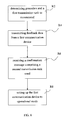
- FIG. 6 a schematic flow chart in a second communication device for signalling control information associated with transmission of data over a wireless channel is shown.
- step S 2 first feedback data is received from a first communication device comprising an indication of recommended precoders and a first transmission rank to possibly use during transmission.
- the indication of recommended precoders corresponds to a frequency-selective precoding report.
- step S 4 the second communication device determines a second transmission rank to use during transmission, wherein the second communication device may, in some embodiments, be arranged to evaluate load in a communication network wherein the first communication device is camped and based on the evaluation the second communication device is arranged to determine second transmission rank to use.
- the step of determining second transmission rank may comprise to take into account the band of frequency used for transmission.
- the step of determining second transmission rank may also, in some embodiments, be based on scheduling of transmission in a cell of the second communication device.
- step S 6 the second communication device performs a transmission of control information comprising a confirmation message to the first communication device.
- the confirmation message comprises a confirmation that transmission of data from the second communication device is using at least parts of each recommended precoder associated with a frequency resource that falls within the transmission of data and an indicator of the second transmission rank to use.
- the confirmation message may comprise a pointer indicating in a table of precoding information confirmation of the precoder used and the determined used second transmission rank.
- the table of precoding information may, in some embodiments, comprise messages allowing a codeword to be individually transmitted on the same layers as the layers used for transmitting the codeword in combination with other codewords as long as the transmission rank is not lower than the number of layers for the codeword.
- each recommended precoder corresponds to a column subset of the associated recommended precoder or a column subset of a generating matrix corresponding to the associated recommended precoder.
- each column subset has the same number of columns and the number of columns corresponds to the second transmission rank.
- the column subsets are selected from the same columns of the recommended precoders or from the same columns of generating matrices corresponding to the recommended precoders.
- each column subset has the same number of columns, columns 1 and 2 from all the recommended precoders.
- every precoder to be used will be the same whereas a recommended precoder of a first sub band is typically different than a recommended precoder of a second sub band.
- the indication of second transmission rank is expressed as which layer/s to which codeword/s to use.
- the indication of recommended precoders corresponds to reporting precoder matrix indicators PMIs
- the indication of a first transmission rank corresponds to reporting a rank indicator RI
- the indication of a second transmission rank corresponds to signalling a transmission rank indication TRI.
- a second communication device is provided.
- FIG. 7 a schematic overview of a second communication device 20 is shown.
- the second communication device 20 is illustrated as a base station, such as a eNodeB, NodeB or the like. It should, however, be understood that the terminology such as base station and UE should be considering non-limiting and does in particular not imply a certain hierarchical relation between the two; in general “base station” could be considered as the first communication device 10 and “UE” the second communication device 20 , and these two devices communicate with each other over some radio channel
- the second communication device 20 comprises a receiving arrangement RX 203 adapted to receive data from a first communication device, wherein the data comprises an indication of recommended precoders and a recommendation of a first transmission rank to possibly use during transmission of data.
- the indication of recommended precoders corresponds to a frequency-selective precoding report.
- the second communication device 20 further comprises a control unit CPU 201 arranged to determine a second transmission rank to use for transmitting data, and a transmitting arrangement TX 205 adapted to transmit a confirmation message to the first communication device.
- the confirmation message comprises a confirmation that the transmission of data is using at least parts of each recommended precoder associated with a frequency resource that falls within the transmission of data and an indicator of the second transmission rank to use.
- the confirmation message may, in some embodiments, comprise a pointer indicating in a table of precoding information confirmation and determined used transmission rank.
- the table may be stored in a memory unit 207 of the second communication device 20 .
- the table of precoding information may comprise messages allowing a codeword to be individually transmitted on the same layers as the layers used for transmitting the codeword in combination with other codewords as long as the transmission rank is not lower than the number of layers for the codeword.
- parts of each recommended precoder may correspond to a column subset of the associated recommended precoder or a column subset of a generating matrix corresponding to the associated recommended precoder.
- the column subset may stored on the memory unit 207 of the second communication device, being an internal/external memory unit.
- Each column subset may in some embodiments have the same number of columns and the number of columns corresponds to the second transmission rank.
- the column subsets may all be selected from the same columns of the recommended precoders or from the same columns of generating matrices corresponding to the recommended precoders.
- the indication of second transmission rank may be expressed as which layer/s to which codeword/s to use.
- the control unit 201 may further be arranged to determine the second transmission rank based on load in a communication network wherein the first communication device is camped, the band of frequency used for transmission, and/or scheduling of transmission within a cell of the second communication device.
- the control unit 201 may be arranged to evaluate load in the network.
- the indication of recommended precoders corresponds to reporting precoder matrix indicators (PMIs), the indication of a first transmission rank corresponds to reporting a rank indicator (RI), and the indication of a second transmission rank corresponds to signalling a transmission rank indication (TRI).
- PMIs precoder matrix indicators
- RI rank indicator
- TRI transmission rank indication
- the second communication device 20 may further comprise an interface 209 to connect to a network or the like.
- the control unit 201 may, in some embodiments, be a central processor unit, a microprocessor, a plurality of processors and/or the like.
- the memory unit 207 may be a single unit, a plurality of memory units, internal and/or external memory.
- FIG. 8 a schematic flow chart of a method in a first communication device for setting the first communication device to an operational mode according to signalled control information associated with transmission of data over a wireless channel is shown.
- the first communication device determines precoders and a first transmission rank to possibly use during transmission of data from the second communication device.
- the decision may be based on the channel quality, for example, a channel measurement in a forward link to the first communication device from a second communication device and/or the like.
- the first communication device transmits feedback data comprising an indication of recommending the determined precoders and the first transmission rank to use to the second communication device.
- the indication of recommended precoders corresponds to a frequency-selective precoding report.
- the first communication device receives control signalling comprising a confirmation message from the second communication device on a radio channel, such as a broadcast channel, unicast channel, or the like.
- the confirmation message comprising a confirmation that transmission of data from the second communication device is using at least parts of each recommended precoder associated with a frequency resource that falls within the transmission of data and an indicator of the second transmission rank used.
- the confirmation message may further comprise a pointer indicating in a table of precoding information confirmation of precoder and the second transmission rank.
- the table of precoding information may, in some embodiments, comprise messages allowing a codeword to be individually transmitted on the same layers as the layers used for transmitting the codeword in combination with other codewords as long as the transmission rank is not lower than the number of layers for the codeword.
- the first communication device reads the pointer to determine precoders and second transmission rank.
- each recommended precoder corresponds to a column subset of the recommended precoder or a column subset of a generating matrix corresponding to the recommended precoder.
- each column subset has the same number of columns and the number of columns corresponds to the second transmission rank.
- the column subsets are selected from the same columns of the recommended precoders or from the same columns of generating matrices corresponding to the recommended precoders.
- the indication of second transmission rank is expressed as which layer/s to which codeword/s to use.
- the indication of recommended precoders corresponds to reporting precoder matrix indicators PMIs
- the indication of a first transmission rank corresponds to reporting a rank indicator RI
- the indication of a second transmission rank corresponds to signalling a transmission rank indication TRI.
- step R 8 the first communication device sets up itself in an operational mode.
- the operational mode uses the second transmission rank and the confirmed at least parts of each recommended precoder to receive and decode the transmission of data from the second communication device.
- a first communication device In order to perform the steps of the method a first communication device is provided.
- FIG. 9 a schematic overview of a first communication device 10 is shown.
- the first communication device is illustrated as a UE, such a mobile phone, PDA or the like. It should, however, be understood that the terminology such as base station and UE should be considering non-limiting and does in particular not imply a certain hierarchical relation between the two; in general “base station” could be considered as the first communication device 10 and “UE” a second communication device 20 , and these two devices communicate with each other over some radio channel.
- the first communication device comprises a control unit 101 , such as a microprocessor or the like, arranged to determine recommended precoders and a first transmission rank to possibly use when a second communication device is transmitting data. The determination may be based on channel measurement/s of received data on a channel from a second communication device.
- a control unit 101 such as a microprocessor or the like, arranged to determine recommended precoders and a first transmission rank to possibly use when a second communication device is transmitting data. The determination may be based on channel measurement/s of received data on a channel from a second communication device.
- the first communication device 10 further comprises a transmitting arrangement 105 arranged to transmit feedback data to the second communication device.
- the feedback data comprises an indication of recommended precoders and the first transmission rank to possibly use during transmission.
- the first communication device 10 further comprises a receiving arrangement 103 arranged to receive, from a second communication device, a confirmation message comprising a confirmation that transmission of data from the second communication device is using at least parts of each recommended precoder associated with a frequency resource that falls within the transmission of data and an indicator of the second transmission rank that is used.
- the control unit 101 is further arranged to setup the first communication device in an operational mode to use the confirmed at least parts of each recommended precoder and the second transmission rank to receive and decode data from the second communication device.
- the control unit 101 may, in some embodiments, further be arranged to perform a channel measurement on a forward link and arranged to determine a recommended precoder and a first transmission rank based on the channel measurement.
- the first communication device 10 may further comprise a table of precoding information
- the confirmation message comprises a pointer indicating in the table confirmation of precoder and the second transmission rank and wherein the control unit 101 is arranged to read the pointer to setup the first communication device into the operational mode.
- the table may be stored on a memory unit 107 , wherein the memory unit may comprise a single unit, a plurality of units; external and/or internal memories.
- the table of precoding information may comprise messages allowing a codeword to be individually transmitted on the same layers as the layers used for transmitting the codeword in combination with other codewords as long as the transmission rank is not lower than the number of layers for the codeword.
- each recommended precoder corresponds to a column subset of the recommended precoder or a column subset of a generating matrix corresponding to the recommended precoder.
- each column subset has the same number of columns and the number of columns corresponds to the second transmission rank.
- the column subsets are selected from the same columns of the recommended precoders or from the same columns of generating matrices corresponding to the recommended precoders.
- the indication of second transmission rank is expressed as which layer/s to which codeword/s to use.
- the indication of recommended precoders corresponds to reporting precoder matrix indicators PMIs
- the indication of a first transmission rank corresponds to reporting a rank indicator RI
- the indication of a second transmission rank corresponds to signalling a transmission rank indication TRI.
Priority Applications (2)
| Application Number | Priority Date | Filing Date | Title |
|---|---|---|---|
| US12/682,161 US8626081B2 (en) | 2007-10-08 | 2008-10-07 | Method and arrangements for signaling control information in a communication system |
| US15/830,065 US11108445B2 (en) | 2007-10-08 | 2017-12-04 | Methods and arrangements for signaling control information in a communication system |
Applications Claiming Priority (3)
| Application Number | Priority Date | Filing Date | Title |
|---|---|---|---|
| US97822607P | 2007-10-08 | 2007-10-08 | |
| US12/682,161 US8626081B2 (en) | 2007-10-08 | 2008-10-07 | Method and arrangements for signaling control information in a communication system |
| PCT/SE2008/051138 WO2009048418A2 (en) | 2007-10-08 | 2008-10-07 | Method and arrangements for signaling control information in a communication system |
Related Parent Applications (1)
| Application Number | Title | Priority Date | Filing Date |
|---|---|---|---|
| PCT/SE2008/051138 A-371-Of-International WO2009048418A2 (en) | 2007-10-08 | 2008-10-07 | Method and arrangements for signaling control information in a communication system |
Related Child Applications (1)
| Application Number | Title | Priority Date | Filing Date |
|---|---|---|---|
| US14/108,823 Continuation US9614602B2 (en) | 2007-10-08 | 2013-12-17 | Methods and arrangements for signaling control information in a communication system |
Publications (2)
| Publication Number | Publication Date |
|---|---|
| US20100304691A1 US20100304691A1 (en) | 2010-12-02 |
| US8626081B2 true US8626081B2 (en) | 2014-01-07 |
Family
ID=40549770
Family Applications (5)
| Application Number | Title | Priority Date | Filing Date |
|---|---|---|---|
| US12/682,161 Active 2029-08-13 US8626081B2 (en) | 2007-10-08 | 2008-10-07 | Method and arrangements for signaling control information in a communication system |
| US14/108,823 Active US9614602B2 (en) | 2007-10-08 | 2013-12-17 | Methods and arrangements for signaling control information in a communication system |
| US15/084,905 Active US9838099B2 (en) | 2007-10-08 | 2016-03-30 | Methods and arrangements for signaling control information in a communication system |
| US15/830,065 Active US11108445B2 (en) | 2007-10-08 | 2017-12-04 | Methods and arrangements for signaling control information in a communication system |
| US17/381,695 Pending US20210351822A1 (en) | 2007-10-08 | 2021-07-21 | Methods and Arrangements for Signaling Control Information in a Communication System |
Family Applications After (4)
| Application Number | Title | Priority Date | Filing Date |
|---|---|---|---|
| US14/108,823 Active US9614602B2 (en) | 2007-10-08 | 2013-12-17 | Methods and arrangements for signaling control information in a communication system |
| US15/084,905 Active US9838099B2 (en) | 2007-10-08 | 2016-03-30 | Methods and arrangements for signaling control information in a communication system |
| US15/830,065 Active US11108445B2 (en) | 2007-10-08 | 2017-12-04 | Methods and arrangements for signaling control information in a communication system |
| US17/381,695 Pending US20210351822A1 (en) | 2007-10-08 | 2021-07-21 | Methods and Arrangements for Signaling Control Information in a Communication System |
Country Status (15)
| Country | Link |
|---|---|
| US (5) | US8626081B2 (es) |
| EP (4) | EP2198533B1 (es) |
| JP (1) | JP5044023B2 (es) |
| CN (1) | CN101821961B (es) |
| CA (1) | CA2701914A1 (es) |
| CO (1) | CO6270280A2 (es) |
| DE (1) | DE202008018547U1 (es) |
| DK (2) | DK2750304T3 (es) |
| ES (3) | ES2737324T3 (es) |
| HU (2) | HUE037533T2 (es) |
| MX (1) | MX2010003639A (es) |
| PL (3) | PL2750304T3 (es) |
| PT (2) | PT3322108T (es) |
| TR (1) | TR201906215T4 (es) |
| WO (1) | WO2009048418A2 (es) |
Cited By (1)
| Publication number | Priority date | Publication date | Assignee | Title |
|---|---|---|---|---|
| US20080260059A1 (en) * | 2007-04-20 | 2008-10-23 | Interdigital Technology Corporation | Method and apparatus for efficient precoding information validation for mimo communications |
Families Citing this family (25)
| Publication number | Priority date | Publication date | Assignee | Title |
|---|---|---|---|---|
| EP2198533B1 (en) | 2007-10-08 | 2013-12-11 | Telefonaktiebolaget LM Ericsson (publ) | Method and arrangements for signaling control information in a communication system |
| US7978623B1 (en) | 2008-03-22 | 2011-07-12 | Freescale Semiconductor, Inc. | Channel rank updates in multiple-input multiple-output communication systems |
| KR101507835B1 (ko) * | 2008-05-08 | 2015-04-06 | 엘지전자 주식회사 | 다중 안테나 시스템에서 전송 다이버시티 방법 |
| TWI514805B (zh) | 2008-07-02 | 2015-12-21 | Interdigital Patent Holdings | 多輸入多輸出通訊排序及預編碼矩陣測量及報告方法及裝置 |
| US8270518B2 (en) * | 2008-07-03 | 2012-09-18 | Texas Instruments Incorporated | Higher order multiple input, multiple output extension |
| SG171738A1 (en) * | 2008-11-14 | 2011-07-28 | Panasonic Corp | Wireless communication terminal apparatus, wireless communication base station apparatus, and cluster constellation setting method |
| JP5007294B2 (ja) * | 2008-12-22 | 2012-08-22 | 株式会社エヌ・ティ・ティ・ドコモ | 無線基地局 |
| PT2465208T (pt) * | 2009-08-14 | 2017-07-24 | ERICSSON TELEFON AB L M (publ) | Dispositivo de antena |
| CN102035580B (zh) * | 2009-09-29 | 2013-10-09 | 上海华为技术有限公司 | 一种空间复用模式中退秩的方法、基站及通信系统 |
| CN102045095B (zh) * | 2009-10-21 | 2014-10-29 | 中兴通讯股份有限公司 | 一种预编码处理方法及装置 |
| US20110170427A1 (en) * | 2010-01-11 | 2011-07-14 | Nokia Corporation | Best Companion PMI-Based Beamforming |
| TWI430596B (zh) | 2010-02-22 | 2014-03-11 | Ralink Technology Corp | 禁用頻道列表產生方法及裝置 |
| ES2750869T3 (es) | 2010-04-07 | 2020-03-27 | Ericsson Telefon Ab L M | Una estructura de precodificador para precodificación MIMO |
| CN102237987B (zh) * | 2010-04-21 | 2014-09-10 | 中兴通讯股份有限公司 | 空间复用模式下harq重传处理方法及装置 |
| US8526383B2 (en) | 2010-05-03 | 2013-09-03 | Telefonaktiebolaget Lm Ericsson (Publ) | System and method for allocating transmission resources based on a transmission rank |
| WO2011159800A1 (en) * | 2010-06-16 | 2011-12-22 | Marvell World Trade Ltd. | Alternate feedback types for downlink multiple user mimo configurations |
| KR101829851B1 (ko) | 2010-08-10 | 2018-03-29 | 마벨 월드 트레이드 리미티드 | 다운링크 복수 사용자 mimo 구조 상의 빔포밍용 서브-대역 피드백 |
| US10009824B2 (en) | 2010-09-01 | 2018-06-26 | Empire Technology Development Llc | Precoding data based on forwarded channel condition information |
| EP2690797B1 (en) * | 2011-03-21 | 2017-06-14 | LG Electronics Inc. | Signal transmitting method and device in a multi-node system. |
| US8965430B2 (en) * | 2011-06-30 | 2015-02-24 | Telefonaktiebolaget L M Ericsson (Publ) | Method and apparatus for controlling channel quality reporting modes used by wireless communication network users |
| US9143267B2 (en) * | 2011-10-27 | 2015-09-22 | Empire Technology Development Llc | Low complexity and power efficient error correction coding schemes |
| CN102611526B (zh) * | 2011-11-08 | 2015-03-25 | 华为技术有限公司 | Mimo系统中发送数据流的方法和装置 |
| US9800308B2 (en) * | 2013-02-18 | 2017-10-24 | Telefonaktiebolaget Lm Ericsson (Publ) | Transmitting node and method for rank determination |
| US10925046B2 (en) | 2017-01-05 | 2021-02-16 | Huawei Technologies Co., Ltd. | Signaling indication for flexible new radio (NR) long term evolution (LTE) coexistence |
| US10396871B2 (en) | 2017-06-15 | 2019-08-27 | At&T Intellectual Property I, L.P. | Layer mapping subset restriction for 5G wireless communication systems |
Citations (6)
| Publication number | Priority date | Publication date | Assignee | Title |
|---|---|---|---|---|
| US20070011550A1 (en) * | 2005-05-31 | 2007-01-11 | Avneesh Agrawal | Rank step-down for MIMO SCW design employing HARQ |
| US20070274411A1 (en) * | 2006-05-26 | 2007-11-29 | Lg Electronics Inc. | Signal generation using phase-shift based pre-coding |
| US20080037675A1 (en) * | 2006-08-14 | 2008-02-14 | Che Lin | Codebook and pre-coder selection for closed-loop mimo |
| US20080043867A1 (en) * | 2006-08-18 | 2008-02-21 | Qualcomm Incorporated | Feedback of precoding control indication (pci) and channel quality indication (cqi) in a wireless communication system |
| US20080186934A1 (en) * | 2007-02-05 | 2008-08-07 | Farooq Khan | MIMO control signaling in a wireless communication system |
| US20080273624A1 (en) * | 2007-05-03 | 2008-11-06 | Mark Kent | Method and system for cqi/pmi feedback for precoded mimo systems utilizing differential codebooks |
Family Cites Families (7)
| Publication number | Priority date | Publication date | Assignee | Title |
|---|---|---|---|---|
| US5974300A (en) | 1996-07-30 | 1999-10-26 | Lucent Technologies Inc. | Two-way wireless cellular messaging system |
| SE0201103D0 (sv) | 2002-04-11 | 2002-04-11 | Ericsson Telefon Ab L M | Diagonally Layered Multi-Antenna Transmission for Frequency Selective Channels |
| US9172453B2 (en) * | 2005-10-27 | 2015-10-27 | Qualcomm Incorporated | Method and apparatus for pre-coding frequency division duplexing system |
| US20070165738A1 (en) | 2005-10-27 | 2007-07-19 | Barriac Gwendolyn D | Method and apparatus for pre-coding for a mimo system |
| US8914015B2 (en) * | 2006-03-20 | 2014-12-16 | Qualcomm Incorporated | Grouping of users for MIMO transmission in a wireless communication system |
| US10044532B2 (en) * | 2006-03-20 | 2018-08-07 | Texas Instruments Incorporated | Pre-coder selection based on resource block grouping |
| EP2198533B1 (en) | 2007-10-08 | 2013-12-11 | Telefonaktiebolaget LM Ericsson (publ) | Method and arrangements for signaling control information in a communication system |
-
2008
- 2008-10-07 EP EP08836979.8A patent/EP2198533B1/en not_active Revoked
- 2008-10-07 DE DE202008018547.5U patent/DE202008018547U1/de not_active Expired - Lifetime
- 2008-10-07 WO PCT/SE2008/051138 patent/WO2009048418A2/en active Application Filing
- 2008-10-07 HU HUE13185095A patent/HUE037533T2/hu unknown
- 2008-10-07 PT PT17210149T patent/PT3322108T/pt unknown
- 2008-10-07 PT PT88369798T patent/PT2198533E/pt unknown
- 2008-10-07 HU HUE17210149A patent/HUE043690T2/hu unknown
- 2008-10-07 TR TR2019/06215T patent/TR201906215T4/tr unknown
- 2008-10-07 PL PL13185095T patent/PL2750304T3/pl unknown
- 2008-10-07 MX MX2010003639A patent/MX2010003639A/es active IP Right Grant
- 2008-10-07 US US12/682,161 patent/US8626081B2/en active Active
- 2008-10-07 ES ES17210149T patent/ES2737324T3/es active Active
- 2008-10-07 ES ES13185095.0T patent/ES2671241T3/es active Active
- 2008-10-07 ES ES08836979.8T patent/ES2443726T3/es active Active
- 2008-10-07 EP EP17210149.5A patent/EP3322108B1/en active Active
- 2008-10-07 CA CA2701914A patent/CA2701914A1/en not_active Abandoned
- 2008-10-07 EP EP19168920.7A patent/EP3644525A1/en active Pending
- 2008-10-07 PL PL17210149T patent/PL3322108T3/pl unknown
- 2008-10-07 CN CN2008801105395A patent/CN101821961B/zh active Active
- 2008-10-07 JP JP2010528840A patent/JP5044023B2/ja active Active
- 2008-10-07 DK DK13185095.0T patent/DK2750304T3/en active
- 2008-10-07 EP EP13185095.0A patent/EP2750304B1/en active Active
- 2008-10-07 DK DK08836979.8T patent/DK2198533T3/en active
- 2008-10-07 PL PL08836979T patent/PL2198533T3/pl unknown
-
2010
- 2010-04-08 CO CO10040506A patent/CO6270280A2/es active IP Right Grant
-
2013
- 2013-12-17 US US14/108,823 patent/US9614602B2/en active Active
-
2016
- 2016-03-30 US US15/084,905 patent/US9838099B2/en active Active
-
2017
- 2017-12-04 US US15/830,065 patent/US11108445B2/en active Active
-
2021
- 2021-07-21 US US17/381,695 patent/US20210351822A1/en active Pending
Patent Citations (6)
| Publication number | Priority date | Publication date | Assignee | Title |
|---|---|---|---|---|
| US20070011550A1 (en) * | 2005-05-31 | 2007-01-11 | Avneesh Agrawal | Rank step-down for MIMO SCW design employing HARQ |
| US20070274411A1 (en) * | 2006-05-26 | 2007-11-29 | Lg Electronics Inc. | Signal generation using phase-shift based pre-coding |
| US20080037675A1 (en) * | 2006-08-14 | 2008-02-14 | Che Lin | Codebook and pre-coder selection for closed-loop mimo |
| US20080043867A1 (en) * | 2006-08-18 | 2008-02-21 | Qualcomm Incorporated | Feedback of precoding control indication (pci) and channel quality indication (cqi) in a wireless communication system |
| US20080186934A1 (en) * | 2007-02-05 | 2008-08-07 | Farooq Khan | MIMO control signaling in a wireless communication system |
| US20080273624A1 (en) * | 2007-05-03 | 2008-11-06 | Mark Kent | Method and system for cqi/pmi feedback for precoded mimo systems utilizing differential codebooks |
Non-Patent Citations (8)
| Title |
|---|
| "On the implementation of rank override using codeword DTX" 3GPP Draft,. R1-074200: 3RD Generation Partnership Project (3GPP) , Mobile Competence Centre , 650. Route Des Lucioles , F-06921 Sophia-Antipolis Cedex , France, [Online] vol. RAN WG1, no . Shanghai , China: 20071008, Oct. 3, 2007, XP050107729 LGE contributions batch 1 for RANI#50bis Retrieved from the Internet: URL:http://list.etsi.orglscripts/wa.exe?A2=ind0710&L=3gpp-tsg-ran-wg1&T=0&P=9421>[retrieved on Jul. 24, 2009]. |
| "On the implementation of rank override using codeword DTX" 3GPP Draft,. R1-074200: 3RD Generation Partnership Project (3GPP) , Mobile Competence Centre , 650. Route Des Lucioles , F-06921 Sophia-Antipolis Cedex , France, [Online] vol. RAN WG1, no . Shanghai , China: 20071008, Oct. 3, 2007, XP050107729 LGE contributions batch 1 for RANI#50bis Retrieved from the Internet: URL:http://list.etsi.orglscripts/wa.exe?A2=ind0710&L=3gpp—tsg—ran—wg1&T=0&P=9421>[retrieved on Jul. 24, 2009]. |
| Dahlman, Eric, et al., 3G Evolution HSPA and LTE for Mobile Broadband, Jun. 2007, Academic Press/Elsevier, First edition, p. 338-339. * |
| Ericsson. Notes form Offline Discussions on PDCCH Contents. R-073870, 3GPP Aug. 24, 2007. |
| LGelectronics: "Downlink-Control Signaling for SU-MIMO" 3GPP Draft; R1-074194 Downlink Control Signaling for SU-MIMO-LGE, 3RD Generation Partnership Project (3GPP), Mobile Competence Centre : 650. Route Des Lucioles ; F-06921 Sophia-Antipolis Cedex ; France, [Online] vol. RAN WG1, no. Shanghai. China: 20071008, Oct. 3, 2007, XP050107723 Two more LGE's contributions for RAN1#50bis Retrieved from the Internet: URL:http://list.etsi.org/scripts/wa.exe?A2=ind0710&L=3gpp-tsg-ran-wg1&T=0&P=17614> [retrieved on Jul. 28, 2009]. |
| LGelectronics: "Downlink-Control Signaling for SU-MIMO" 3GPP Draft; R1-074194 Downlink Control Signaling for SU-MIMO—LGE, 3RD Generation Partnership Project (3GPP), Mobile Competence Centre : 650. Route Des Lucioles ; F-06921 Sophia-Antipolis Cedex ; France, [Online] vol. RAN WG1, no. Shanghai. China: 20071008, Oct. 3, 2007, XP050107723 Two more LGE's contributions for RAN1#50bis Retrieved from the Internet: URL:http://list.etsi.org/scripts/wa.exe?A2=ind0710&L=3gpp—tsg—ran—wg1&T=0&P=17614> [retrieved on Jul. 28, 2009]. |
| Motorola. PMI Downlink Signaling and PDCCH Format. R1-073378; 3GPP Aug. 24, 2007. |
| Philippines Office Action Dated Sep. 27, 2013, 3 pages. |
Cited By (3)
| Publication number | Priority date | Publication date | Assignee | Title |
|---|---|---|---|---|
| US20080260059A1 (en) * | 2007-04-20 | 2008-10-23 | Interdigital Technology Corporation | Method and apparatus for efficient precoding information validation for mimo communications |
| US9716604B2 (en) * | 2007-04-20 | 2017-07-25 | Interdigital Technology Corporation | Method and apparatus for efficient precoding information validation for MIMO communications |
| US10284265B2 (en) | 2007-04-20 | 2019-05-07 | Interdigital Technology Corporation | Method and apparatus for efficient precoding information validation for MIMO communications |
Also Published As
Similar Documents
| Publication | Publication Date | Title |
|---|---|---|
| US20210351822A1 (en) | Methods and Arrangements for Signaling Control Information in a Communication System | |
| US9698881B2 (en) | Feedback channel transmission and detection in multi antenna wireless communication systems | |
| KR102257265B1 (ko) | Cqi 정보 수신 방법, 송신 방법, 수신 디바이스 및 송신 디바이스 | |
| JP5647195B2 (ja) | 多重入出力システムにおけるチャンネル品質情報フィードバック方法、データ伝送方法、ユーザ機器及び基地局 | |
| US20200136682A1 (en) | Multi-beam csi reporting | |
| US8155103B2 (en) | Support for retransmitting a transport block with a different number of layers than a previous transmission attempt | |
| JP2011521502A (ja) | Mimoシステムにおいてプリコーディング情報を伝送するための方法及び装置 | |
| US10505614B2 (en) | CSI feedback method, precoding method, and apparatus | |
| KR20150028335A (ko) | 무선 통신 장치, 및 harq 응답의 송신 방법 및 수신 방법 | |
| WO2017076220A1 (zh) | 一种信道状态信息csi反馈方法、终端及基站 | |
| WO2011054126A1 (zh) | 自适应隐性反馈方法和用户设备 |
Legal Events
| Date | Code | Title | Description |
|---|---|---|---|
| AS | Assignment |
Owner name: TELEFONAKTIEBOLAGET LM ERICSSON (PUBL), SWEDEN Free format text: ASSIGNMENT OF ASSIGNORS INTEREST;ASSIGNORS:JONGREN, GEORGE;GORANSSON, BO;SIGNING DATES FROM 20080429 TO 20080512;REEL/FRAME:024886/0820 |
|
| STCF | Information on status: patent grant |
Free format text: PATENTED CASE |
|
| FPAY | Fee payment |
Year of fee payment: 4 |
|
| MAFP | Maintenance fee payment |
Free format text: PAYMENT OF MAINTENANCE FEE, 8TH YEAR, LARGE ENTITY (ORIGINAL EVENT CODE: M1552); ENTITY STATUS OF PATENT OWNER: LARGE ENTITY Year of fee payment: 8 |