US8624466B2 - Component having stress-reduced mounting - Google Patents
Component having stress-reduced mounting Download PDFInfo
- Publication number
- US8624466B2 US8624466B2 US12/665,385 US66538508A US8624466B2 US 8624466 B2 US8624466 B2 US 8624466B2 US 66538508 A US66538508 A US 66538508A US 8624466 B2 US8624466 B2 US 8624466B2
- Authority
- US
- United States
- Prior art keywords
- component
- membrane
- substrate
- suspension
- modulus
- Prior art date
- Legal status (The legal status is an assumption and is not a legal conclusion. Google has not performed a legal analysis and makes no representation as to the accuracy of the status listed.)
- Expired - Fee Related, expires
Links
Images


Classifications
-
- H—ELECTRICITY
- H03—ELECTRONIC CIRCUITRY
- H03H—IMPEDANCE NETWORKS, e.g. RESONANT CIRCUITS; RESONATORS
- H03H9/00—Networks comprising electromechanical or electro-acoustic elements; Electromechanical resonators
- H03H9/15—Constructional features of resonators consisting of piezoelectric or electrostrictive material
- H03H9/17—Constructional features of resonators consisting of piezoelectric or electrostrictive material having a single resonator
- H03H9/171—Constructional features of resonators consisting of piezoelectric or electrostrictive material having a single resonator implemented with thin-film techniques, i.e. of the film bulk acoustic resonator [FBAR] type
- H03H9/172—Means for mounting on a substrate, i.e. means constituting the material interface confining the waves to a volume
- H03H9/173—Air-gaps
-
- H—ELECTRICITY
- H03—ELECTRONIC CIRCUITRY
- H03H—IMPEDANCE NETWORKS, e.g. RESONANT CIRCUITS; RESONATORS
- H03H9/00—Networks comprising electromechanical or electro-acoustic elements; Electromechanical resonators
- H03H9/02—Details
- H03H9/02007—Details of bulk acoustic wave devices
- H03H9/02086—Means for compensation or elimination of undesirable effects
- H03H9/02133—Means for compensation or elimination of undesirable effects of stress
-
- H—ELECTRICITY
- H03—ELECTRONIC CIRCUITRY
- H03H—IMPEDANCE NETWORKS, e.g. RESONANT CIRCUITS; RESONATORS
- H03H9/00—Networks comprising electromechanical or electro-acoustic elements; Electromechanical resonators
- H03H9/02—Details
- H03H9/05—Holders or supports
- H03H9/09—Elastic or damping supports
-
- H—ELECTRICITY
- H03—ELECTRONIC CIRCUITRY
- H03H—IMPEDANCE NETWORKS, e.g. RESONANT CIRCUITS; RESONATORS
- H03H9/00—Networks comprising electromechanical or electro-acoustic elements; Electromechanical resonators
- H03H9/15—Constructional features of resonators consisting of piezoelectric or electrostrictive material
- H03H9/17—Constructional features of resonators consisting of piezoelectric or electrostrictive material having a single resonator
- H03H9/171—Constructional features of resonators consisting of piezoelectric or electrostrictive material having a single resonator implemented with thin-film techniques, i.e. of the film bulk acoustic resonator [FBAR] type
- H03H9/172—Means for mounting on a substrate, i.e. means constituting the material interface confining the waves to a volume
- H03H9/174—Membranes
Definitions
- One object to be achieved consists in specifying a component fixture which enables a component, for example a piezoelement, to be fixed to a substrate without mechanical stresses.
- the component is applied at the top on a substrate by means of an elastic suspension, such that the component can move relative to the substrate.
- the suspension preferably comprises an elastic element.
- the modulus of elasticity of the elastic element is lower than the modulus of elasticity of the component or of the substrate.
- the suspension is suitable for stress-sensitive components, in particular MEMS components. Furthermore, the suspension is suitable for a component having micromechanical structures which are sensitive to mechanical stresses in the suspension.
- the component is preferably a bridge-type BAW resonator.
- the elastic element is embodied as a membrane which is stretched over the substrate and with which the component is suspended above the substrate.
- a soft frame In order to connect the component to a substrate without laterally clamping it in, which can lead to mechanical strains, a soft frame can be fitted around the component, which frame can absorb strains. The substrate and the component are thus mechanically decoupled from one another.
- the frame preferably has a significantly lower modulus of elasticity (Young's modulus) E and thus a lower stiffness than the materials used in the component.
- This lower stiffness can be achieved by means of a soft polymer or by means of a very thin and possibly structured metal layer.
- BCB benzocyclobutene
- E 10 GPa
- a spring element is used for suspending the component above the substrate.
- Said spring element is preferably arranged between substrate and component.
- a leaf spring is involved in this case.
- connection between component and substrate by means of a frame have a strength which suffices for fixing the component above the substrate.
- the component can rest on the substrate, or be separated by an air gap.
- the connection is soft enough to compensate for mechanical stresses.
- Mechanical stresses can arise for example during the production process or in subsequent operation as a result of temperature changes.
- the substrate preferably has a depression below the component, said depression being spanned by the membrane.
- the depression reaches through the entire substrate.
- the substrate then has an opening spanned by the membrane.
- the edge of the component is preferably situated above the margin of the substrate. However, the edges can also be situated completely above the depression.
- the suspension of the component is effected at the side edges thereof.
- the component rests with a lower marginal region on the membrane.
- the suspension of the component can be effected by means of marginal regions of the component at the underside of the membrane.
- the membrane can also cover larger regions of the component or the entire surface of the component.
- the component has metal electrodes on a first and a second side, which metal electrodes can be drawn back in regions of the suspension in order to decouple the acoustically active region from the suspension.
- the soft membrane can absorb the strains that are caused by production and/or arise as a result of different temperature coefficients of expansion.
- a static pressure can build up in the depression in the substrate in a manner governed by temperature.
- a pressure equalizing opening is provided in the membrane, through which the pressure can escape toward the outside.
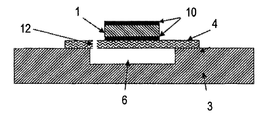
- FIG. 1 shows a first embodiment, wherein the substrate has a depression below the resonator.
- FIG. 2 shows a second embodiment, wherein an opening is situated in the substrate below the resonator.
- FIGS. 3 a - 3 c show different variants of the suspension of the resonator with the aid of a membrane.
- FIGS. 4 a - 4 d show different variants of the suspension of the resonator with partially drawn-back regions of the metal electrodes.
- FIG. 5 shows a further embodiment, wherein the suspension of the resonator at the substrate is effected by means of a spring.
- FIG. 1 illustrates a first exemplary embodiment, wherein the component 1 is suspended by means of a membrane 4 .
- a depression 6 is situated in the substrate 3 below the membrane 4 , said depression decoupling the component 1 from the substrate.
- the component 1 rests on the membrane 4 .
- a pressure equalizing opening 12 is situated in the membrane 4 .
- Said pressure equalizing opening 12 serves for equalizing the static pressure that can form in the depression 6 during operation as a result of temperature changes.
- the component embodied here as a resonator operating with bulk acoustic waves, comprises a piezoelectric layer having metal electrodes 10 on two sides.
- the membrane has a lower stiffness than the component and is formed from a polymer, in particular.
- the elastic membrane ensures that no lateral strain of the resonator with the substrate can occur.
- the elastic and compliant membrane can absorb forces that have occurred in the case of different thermal expansions or in the case of strains that have occurred in the production process, such that the resonator or the MEMS component is suspended in a strain-free state.
- FIG. 2 illustrates a further exemplary embodiment, wherein an opening 7 is situated in the substrate 3 below the component 1 .
- Said opening 7 is spanned by a membrane 4 .
- a pressure equalizing opening 12 Situated in the membrane 4 is a pressure equalizing opening 12 , which can also be dispensed with, however, owing to the opening 7 of the substrate 3 being open “at the bottom”.
- FIG. 3 a illustrates a further variant of the fixture of the component 1 above a depression 6 .
- the membrane 4 is stretched over the component, such that the component 1 has a free region 11 on the side which is remote from the membrane 4 but faces the substrate 3 , said free region preferably comprising the entire underside of the component 1 .
- the membrane 4 preferably bears against the side edges 8 of the component 1 .
- FIG. 3 b illustrates a further exemplary embodiment, wherein the component 1 rests only with a marginal region 9 on the membrane 4 above the depression 6 in the substrate 3 .
- the component 1 can have on the underside a region 11 free of the membrane 4 , said region corresponding to a cutout in the membrane 4 .
- FIG. 3 c A further exemplary embodiment is shown in FIG. 3 c .
- the component 1 is held by the membrane 4 at the side edges 8 of the component 1 .
- the component 1 can have both on the underside and on the top side a region 11 free of the membrane 4 .
- the variants 4 a to 4 d show exemplary embodiments in which the metal electrodes 10 on the component 1 are drawn back in marginal regions 9 in order that the acoustically active regions are decoupled from the membrane.
- FIG. 4 a the component 1 rests only with a marginal region 9 on the membrane 4 and in this case covers a cutout provided in the membrane 4 , such that a free region 11 can occur on the underside of the component 1 .
- the metal electrodes 10 are drawn back on both sides here, such that the component 1 can have regions free of metal electrodes 10 on the top side and underside.
- the fixture of the component 1 is effected by means of the side edges 8 of the component 1 .
- the membrane 4 can cover a narrow marginal region 9 of the component 1 on the top side of the component 1 .
- the regions with metal electrodes 10 are drawn back from the component edge on both sides and are not in contact with the membrane 4 .
- the metal electrodes 10 are drawn back only on the top side of the component 1 .
- the underside of the component 1 is covered with a metal electrode 10 over the area.
- the fixture of the component 1 is effected by means of the side edges 8 thereof.
- the membrane 4 can cover a narrow marginal region of the top side of the component 1 , but is preferably not in contact with the metal electrodes 10 on the top side, such that the membrane 4 does not cause any vibration damping of the component 1 embodied as a resonator.
- FIG. 4 d shows an embodiment variant in which the metal electrodes 10 are drawn back only on the underside of the component 1 and are thereby decoupled from the fixture.
- the fixture is effected by means of the side edges 8 of the component 1 .
- the membrane 4 can cover a narrow marginal region 9 on the top side of the component 1 and therefore also a narrow marginal region of the upper metal electrodes 10 . Since this marginal region, owing to the metal electrodes 10 drawn back at the bottom, does not belong to the active region of the resonator, no damping of resonator vibrations occurs here either.
- FIG. 5 shows a variant of the fixture of the component 1 to the substrate 3 in which the suspension is effected by means of a spring element 2 .
- the component 1 is fixed above a depression 6 with the aid of the spring element 2 .
- the invention is not restricted to them. It is possible, in principle, for the membrane also to cover other regions of the component, or for the fixture of the component to be effected not just by means of the side edges or marginal regions. It is also conceivable for a plurality of depressions to be situated below the component or for a plurality of components to be arranged on a substrate and to be fixed above a common or a plurality of separate depressions by means of a membrane or some other suspension.
- the component is not restricted to the number of schematically illustrated elements.
Landscapes
- Physics & Mathematics (AREA)
- Acoustics & Sound (AREA)
- Piezo-Electric Or Mechanical Vibrators, Or Delay Or Filter Circuits (AREA)
- Structures For Mounting Electric Components On Printed Circuit Boards (AREA)
Abstract
Description
Claims (22)
Applications Claiming Priority (3)
| Application Number | Priority Date | Filing Date | Title |
|---|---|---|---|
| DE102007028292 | 2007-06-20 | ||
| DE102007028292.5A DE102007028292B4 (en) | 2007-06-20 | 2007-06-20 | Component with reduced voltage attachment |
| PCT/EP2008/057498 WO2008155296A2 (en) | 2007-06-20 | 2008-06-13 | Component having stress-reduced mounting |
Publications (2)
| Publication Number | Publication Date |
|---|---|
| US20100176899A1 US20100176899A1 (en) | 2010-07-15 |
| US8624466B2 true US8624466B2 (en) | 2014-01-07 |
Family
ID=39719229
Family Applications (1)
| Application Number | Title | Priority Date | Filing Date |
|---|---|---|---|
| US12/665,385 Expired - Fee Related US8624466B2 (en) | 2007-06-20 | 2008-06-13 | Component having stress-reduced mounting |
Country Status (4)
| Country | Link |
|---|---|
| US (1) | US8624466B2 (en) |
| JP (1) | JP2010535436A (en) |
| DE (1) | DE102007028292B4 (en) |
| WO (1) | WO2008155296A2 (en) |
Families Citing this family (28)
| Publication number | Priority date | Publication date | Assignee | Title |
|---|---|---|---|---|
| US8981876B2 (en) | 2004-11-15 | 2015-03-17 | Avago Technologies General Ip (Singapore) Pte. Ltd. | Piezoelectric resonator structures and electrical filters having frame elements |
| US7791434B2 (en) * | 2004-12-22 | 2010-09-07 | Avago Technologies Wireless Ip (Singapore) Pte. Ltd. | Acoustic resonator performance enhancement using selective metal etch and having a trench in the piezoelectric |
| US8542850B2 (en) * | 2007-09-12 | 2013-09-24 | Epcos Pte Ltd | Miniature microphone assembly with hydrophobic surface coating |
| DE102007058951B4 (en) * | 2007-12-07 | 2020-03-26 | Snaptrack, Inc. | MEMS package |
| US8902023B2 (en) | 2009-06-24 | 2014-12-02 | Avago Technologies General Ip (Singapore) Pte. Ltd. | Acoustic resonator structure having an electrode with a cantilevered portion |
| US8248185B2 (en) | 2009-06-24 | 2012-08-21 | Avago Technologies Wireless Ip (Singapore) Pte. Ltd. | Acoustic resonator structure comprising a bridge |
| US8796904B2 (en) | 2011-10-31 | 2014-08-05 | Avago Technologies General Ip (Singapore) Pte. Ltd. | Bulk acoustic resonator comprising piezoelectric layer and inverse piezoelectric layer |
| US9243316B2 (en) | 2010-01-22 | 2016-01-26 | Avago Technologies General Ip (Singapore) Pte. Ltd. | Method of fabricating piezoelectric material with selected c-axis orientation |
| DE102010006132B4 (en) | 2010-01-29 | 2013-05-08 | Epcos Ag | Miniaturized electrical component with a stack of a MEMS and an ASIC |
| JP5510465B2 (en) * | 2010-02-09 | 2014-06-04 | 株式会社村田製作所 | Piezoelectric device and method for manufacturing piezoelectric device |
| US8962443B2 (en) | 2011-01-31 | 2015-02-24 | Avago Technologies General Ip (Singapore) Pte. Ltd. | Semiconductor device having an airbridge and method of fabricating the same |
| US9425764B2 (en) | 2012-10-25 | 2016-08-23 | Avago Technologies General Ip (Singapore) Pte. Ltd. | Accoustic resonator having composite electrodes with integrated lateral features |
| US9148117B2 (en) | 2011-02-28 | 2015-09-29 | Avago Technologies General Ip (Singapore) Pte. Ltd. | Coupled resonator filter comprising a bridge and frame elements |
| US9203374B2 (en) | 2011-02-28 | 2015-12-01 | Avago Technologies General Ip (Singapore) Pte. Ltd. | Film bulk acoustic resonator comprising a bridge |
| US9154112B2 (en) | 2011-02-28 | 2015-10-06 | Avago Technologies General Ip (Singapore) Pte. Ltd. | Coupled resonator filter comprising a bridge |
| US9048812B2 (en) | 2011-02-28 | 2015-06-02 | Avago Technologies General Ip (Singapore) Pte. Ltd. | Bulk acoustic wave resonator comprising bridge formed within piezoelectric layer |
| US9083302B2 (en) | 2011-02-28 | 2015-07-14 | Avago Technologies General Ip (Singapore) Pte. Ltd. | Stacked bulk acoustic resonator comprising a bridge and an acoustic reflector along a perimeter of the resonator |
| US9136818B2 (en) | 2011-02-28 | 2015-09-15 | Avago Technologies General Ip (Singapore) Pte. Ltd. | Stacked acoustic resonator comprising a bridge |
| US8575820B2 (en) | 2011-03-29 | 2013-11-05 | Avago Technologies General Ip (Singapore) Pte. Ltd. | Stacked bulk acoustic resonator |
| US9444426B2 (en) | 2012-10-25 | 2016-09-13 | Avago Technologies General Ip (Singapore) Pte. Ltd. | Accoustic resonator having integrated lateral feature and temperature compensation feature |
| US8450913B1 (en) * | 2011-03-31 | 2013-05-28 | Georgia Tech Research Corporation | Tunable Piezoelectric MEMS Resonators suitable for real-time clock applications |
| US8872604B2 (en) | 2011-05-05 | 2014-10-28 | Avago Technologies General Ip (Singapore) Pte. Ltd. | Double film bulk acoustic resonators with electrode layer and piezo-electric layer thicknesses providing improved quality factor |
| US8350445B1 (en) | 2011-06-16 | 2013-01-08 | Avago Technologies Wireless Ip (Singapore) Pte. Ltd. | Bulk acoustic resonator comprising non-piezoelectric layer and bridge |
| US8922302B2 (en) | 2011-08-24 | 2014-12-30 | Avago Technologies General Ip (Singapore) Pte. Ltd. | Acoustic resonator formed on a pedestal |
| US9667220B2 (en) | 2012-01-30 | 2017-05-30 | Avago Technologies General Ip (Singapore) Pte. Ltd. | Temperature controlled acoustic resonator comprising heater and sense resistors |
| US9667218B2 (en) | 2012-01-30 | 2017-05-30 | Avago Technologies General Ip (Singapore) Pte. Ltd. | Temperature controlled acoustic resonator comprising feedback circuit |
| US9608592B2 (en) | 2014-01-21 | 2017-03-28 | Avago Technologies General Ip (Singapore) Pte. Ltd. | Film bulk acoustic wave resonator (FBAR) having stress-relief |
| US9154103B2 (en) | 2012-01-30 | 2015-10-06 | Avago Technologies General Ip (Singapore) Pte. Ltd. | Temperature controlled acoustic resonator |
Citations (6)
| Publication number | Priority date | Publication date | Assignee | Title |
|---|---|---|---|---|
| EP1191559A2 (en) * | 2000-09-01 | 2002-03-27 | Little Things Factory GmbH | Micro-switch and method of manufacturing the same |
| US6366186B1 (en) * | 2000-01-20 | 2002-04-02 | Jds Uniphase Inc. | Mems magnetically actuated switches and associated switching arrays |
| US20030076664A1 (en) | 2000-04-05 | 2003-04-24 | Milasys Gbr | Micro-functional unit |
| EP0834989B1 (en) | 1996-10-02 | 2003-09-10 | Nokia Corporation | A device incorporating a tunable thin film bulk acoustic resonator for performing amplitude and phase modulation |
| US20040029356A1 (en) * | 2001-01-18 | 2004-02-12 | Hans-Jorg Timme | Filter device and method for fabricating filter devices |
| US20050128027A1 (en) * | 2003-10-07 | 2005-06-16 | Samsung Electronics Co., Ltd. | Air-gap type FBAR, method for fabricating the same, and filter and duplexer using the same |
-
2007
- 2007-06-20 DE DE102007028292.5A patent/DE102007028292B4/en not_active Expired - Fee Related
-
2008
- 2008-06-13 JP JP2010512655A patent/JP2010535436A/en not_active Withdrawn
- 2008-06-13 US US12/665,385 patent/US8624466B2/en not_active Expired - Fee Related
- 2008-06-13 WO PCT/EP2008/057498 patent/WO2008155296A2/en not_active Ceased
Patent Citations (6)
| Publication number | Priority date | Publication date | Assignee | Title |
|---|---|---|---|---|
| EP0834989B1 (en) | 1996-10-02 | 2003-09-10 | Nokia Corporation | A device incorporating a tunable thin film bulk acoustic resonator for performing amplitude and phase modulation |
| US6366186B1 (en) * | 2000-01-20 | 2002-04-02 | Jds Uniphase Inc. | Mems magnetically actuated switches and associated switching arrays |
| US20030076664A1 (en) | 2000-04-05 | 2003-04-24 | Milasys Gbr | Micro-functional unit |
| EP1191559A2 (en) * | 2000-09-01 | 2002-03-27 | Little Things Factory GmbH | Micro-switch and method of manufacturing the same |
| US20040029356A1 (en) * | 2001-01-18 | 2004-02-12 | Hans-Jorg Timme | Filter device and method for fabricating filter devices |
| US20050128027A1 (en) * | 2003-10-07 | 2005-06-16 | Samsung Electronics Co., Ltd. | Air-gap type FBAR, method for fabricating the same, and filter and duplexer using the same |
Also Published As
| Publication number | Publication date |
|---|---|
| WO2008155296A2 (en) | 2008-12-24 |
| JP2010535436A (en) | 2010-11-18 |
| DE102007028292B4 (en) | 2019-06-19 |
| US20100176899A1 (en) | 2010-07-15 |
| DE102007028292A1 (en) | 2008-12-24 |
| WO2008155296A3 (en) | 2009-03-26 |
Similar Documents
| Publication | Publication Date | Title |
|---|---|---|
| US8624466B2 (en) | Component having stress-reduced mounting | |
| US9386379B2 (en) | MEMS microphone | |
| US8058769B2 (en) | Mechanical resonating structures including a temperature compensation structure | |
| US8526642B2 (en) | Piezoelectric micro speaker including weight attached to vibrating membrane and method of manufacturing the same | |
| US12404167B2 (en) | Piezoelectric MEMS device with thermal compensation from different material thicknesses | |
| CN101584226B (en) | Microphone with pressure relief | |
| JP7721170B2 (en) | Bone conduction acoustic transmission device | |
| US20110272769A1 (en) | Mems microphone package and packaging method | |
| CN106688246B (en) | Capacitance converter and acoustic sensor | |
| CN103688556A (en) | Components with micromechanical microphone structures | |
| KR101758017B1 (en) | Piezo mems microphone and thereof manufacturing method | |
| CN111146328A (en) | Single crystal piezoelectric structure and electronic device having the same | |
| WO2007088696A1 (en) | Piezoelectric oscillator | |
| CN115210891B (en) | piezoelectric devices | |
| US20250080919A1 (en) | Mems sound transducer and method for producing same | |
| US9743195B2 (en) | Acoustic sensor | |
| WO2011040233A1 (en) | Sensor device | |
| US10351416B2 (en) | Module comprising a MEMS component mounted without subjecting same to stress | |
| KR101066102B1 (en) | Micro speaker and its manufacturing method | |
| CN116349251B (en) | Electrostatic converter and method for manufacturing electrostatic converter | |
| WO2024051509A1 (en) | Mems loudspeaker having stretchable film, manufacturing method therefor, and electronic device comprising same | |
| US20250074762A1 (en) | Mems sound transducer and method for producing same | |
| JP2023044406A (en) | Piezoelectric element | |
| CN120224087A (en) | Piezoelectric sound transducer and method for manufacturing the same | |
| CN118575488A (en) | MEMS element |
Legal Events
| Date | Code | Title | Description |
|---|---|---|---|
| AS | Assignment |
Owner name: EPCOS AG, GERMANY Free format text: ASSIGNMENT OF ASSIGNORS INTEREST;ASSIGNORS:SCHAUFELE, ANSGAR;LEIDL, ANTON;SAUER, WOLFGANG;SIGNING DATES FROM 20100126 TO 20100226;REEL/FRAME:024071/0402 |
|
| STCF | Information on status: patent grant |
Free format text: PATENTED CASE |
|
| FEPP | Fee payment procedure |
Free format text: PAYOR NUMBER ASSIGNED (ORIGINAL EVENT CODE: ASPN); ENTITY STATUS OF PATENT OWNER: LARGE ENTITY |
|
| AS | Assignment |
Owner name: SNAPTRACK, INC., CALIFORNIA Free format text: ASSIGNMENT OF ASSIGNORS INTEREST;ASSIGNOR:EPCOS AG;REEL/FRAME:041608/0145 Effective date: 20170201 |
|
| FPAY | Fee payment |
Year of fee payment: 4 |
|
| FEPP | Fee payment procedure |
Free format text: MAINTENANCE FEE REMINDER MAILED (ORIGINAL EVENT CODE: REM.); ENTITY STATUS OF PATENT OWNER: LARGE ENTITY |
|
| LAPS | Lapse for failure to pay maintenance fees |
Free format text: PATENT EXPIRED FOR FAILURE TO PAY MAINTENANCE FEES (ORIGINAL EVENT CODE: EXP.); ENTITY STATUS OF PATENT OWNER: LARGE ENTITY |
|
| STCH | Information on status: patent discontinuation |
Free format text: PATENT EXPIRED DUE TO NONPAYMENT OF MAINTENANCE FEES UNDER 37 CFR 1.362 |
|
| FP | Lapsed due to failure to pay maintenance fee |
Effective date: 20220107 |