US8623106B2 - Fluid reforming apparatus for maintaining thermal conductivity of a fluid in a flow channel - Google Patents
Fluid reforming apparatus for maintaining thermal conductivity of a fluid in a flow channel Download PDFInfo
- Publication number
- US8623106B2 US8623106B2 US12/373,406 US37340607A US8623106B2 US 8623106 B2 US8623106 B2 US 8623106B2 US 37340607 A US37340607 A US 37340607A US 8623106 B2 US8623106 B2 US 8623106B2
- Authority
- US
- United States
- Prior art keywords
- fluid
- pressure
- catalyst
- flow channel
- reforming apparatus
- Prior art date
- Legal status (The legal status is an assumption and is not a legal conclusion. Google has not performed a legal analysis and makes no representation as to the accuracy of the status listed.)
- Expired - Fee Related, expires
Links
- 239000012530 fluid Substances 0.000 title claims abstract description 119
- 238000002407 reforming Methods 0.000 title claims abstract description 60
- 239000003054 catalyst Substances 0.000 claims abstract description 78
- 238000010438 heat treatment Methods 0.000 claims abstract description 42
- 239000000446 fuel Substances 0.000 claims description 107
- 239000000376 reactant Substances 0.000 claims description 13
- 239000003502 gasoline Substances 0.000 claims description 11
- 238000011144 upstream manufacturing Methods 0.000 claims description 9
- 239000000203 mixture Substances 0.000 claims description 7
- CURLTUGMZLYLDI-UHFFFAOYSA-N Carbon dioxide Chemical compound O=C=O CURLTUGMZLYLDI-UHFFFAOYSA-N 0.000 claims description 6
- MWUXSHHQAYIFBG-UHFFFAOYSA-N Nitric oxide Chemical compound O=[N] MWUXSHHQAYIFBG-UHFFFAOYSA-N 0.000 claims description 6
- MHAJPDPJQMAIIY-UHFFFAOYSA-N Hydrogen peroxide Chemical compound OO MHAJPDPJQMAIIY-UHFFFAOYSA-N 0.000 claims description 4
- 229930195733 hydrocarbon Natural products 0.000 claims description 4
- 150000002430 hydrocarbons Chemical class 0.000 claims description 4
- 239000002551 biofuel Substances 0.000 claims description 3
- 239000001569 carbon dioxide Substances 0.000 claims description 3
- 229910002092 carbon dioxide Inorganic materials 0.000 claims description 3
- 239000003949 liquefied natural gas Substances 0.000 claims description 3
- 239000003915 liquefied petroleum gas Substances 0.000 claims description 3
- 150000001298 alcohols Chemical class 0.000 claims description 2
- QVGXLLKOCUKJST-UHFFFAOYSA-N atomic oxygen Chemical compound [O] QVGXLLKOCUKJST-UHFFFAOYSA-N 0.000 claims description 2
- 239000003921 oil Substances 0.000 claims description 2
- 239000001301 oxygen Substances 0.000 claims description 2
- 229910052760 oxygen Inorganic materials 0.000 claims description 2
- XLYOFNOQVPJJNP-UHFFFAOYSA-N water Substances O XLYOFNOQVPJJNP-UHFFFAOYSA-N 0.000 claims description 2
- 229910001868 water Inorganic materials 0.000 claims description 2
- IMNFDUFMRHMDMM-UHFFFAOYSA-N N-Heptane Chemical compound CCCCCCC IMNFDUFMRHMDMM-UHFFFAOYSA-N 0.000 description 42
- 238000004088 simulation Methods 0.000 description 12
- 238000005245 sintering Methods 0.000 description 10
- 230000003247 decreasing effect Effects 0.000 description 8
- 230000006866 deterioration Effects 0.000 description 8
- OKTJSMMVPCPJKN-UHFFFAOYSA-N Carbon Chemical compound [C] OKTJSMMVPCPJKN-UHFFFAOYSA-N 0.000 description 7
- 229910052799 carbon Inorganic materials 0.000 description 7
- 239000011247 coating layer Substances 0.000 description 7
- 230000008021 deposition Effects 0.000 description 7
- 238000000034 method Methods 0.000 description 5
- BASFCYQUMIYNBI-UHFFFAOYSA-N platinum Chemical compound [Pt] BASFCYQUMIYNBI-UHFFFAOYSA-N 0.000 description 4
- OKKJLVBELUTLKV-UHFFFAOYSA-N Methanol Chemical compound OC OKKJLVBELUTLKV-UHFFFAOYSA-N 0.000 description 3
- 238000006243 chemical reaction Methods 0.000 description 3
- 238000009413 insulation Methods 0.000 description 3
- 238000006057 reforming reaction Methods 0.000 description 3
- 239000004215 Carbon black (E152) Substances 0.000 description 2
- KDLHZDBZIXYQEI-UHFFFAOYSA-N Palladium Chemical compound [Pd] KDLHZDBZIXYQEI-UHFFFAOYSA-N 0.000 description 2
- 229910001069 Ti alloy Inorganic materials 0.000 description 2
- GWEVSGVZZGPLCZ-UHFFFAOYSA-N Titan oxide Chemical compound O=[Ti]=O GWEVSGVZZGPLCZ-UHFFFAOYSA-N 0.000 description 2
- MCMNRKCIXSYSNV-UHFFFAOYSA-N Zirconium dioxide Chemical compound O=[Zr]=O MCMNRKCIXSYSNV-UHFFFAOYSA-N 0.000 description 2
- 239000002828 fuel tank Substances 0.000 description 2
- 229910000856 hastalloy Inorganic materials 0.000 description 2
- 229910001026 inconel Inorganic materials 0.000 description 2
- 239000007788 liquid Substances 0.000 description 2
- 229910044991 metal oxide Inorganic materials 0.000 description 2
- 150000004706 metal oxides Chemical class 0.000 description 2
- 229910052697 platinum Inorganic materials 0.000 description 2
- 238000005979 thermal decomposition reaction Methods 0.000 description 2
- LFQSCWFLJHTTHZ-UHFFFAOYSA-N Ethanol Chemical compound CCO LFQSCWFLJHTTHZ-UHFFFAOYSA-N 0.000 description 1
- UFHFLCQGNIYNRP-UHFFFAOYSA-N Hydrogen Chemical compound [H][H] UFHFLCQGNIYNRP-UHFFFAOYSA-N 0.000 description 1
- BQCADISMDOOEFD-UHFFFAOYSA-N Silver Chemical compound [Ag] BQCADISMDOOEFD-UHFFFAOYSA-N 0.000 description 1
- XHCLAFWTIXFWPH-UHFFFAOYSA-N [O-2].[O-2].[O-2].[O-2].[O-2].[V+5].[V+5] Chemical compound [O-2].[O-2].[O-2].[O-2].[O-2].[V+5].[V+5] XHCLAFWTIXFWPH-UHFFFAOYSA-N 0.000 description 1
- PNEYBMLMFCGWSK-UHFFFAOYSA-N aluminium oxide Inorganic materials [O-2].[O-2].[O-2].[Al+3].[Al+3] PNEYBMLMFCGWSK-UHFFFAOYSA-N 0.000 description 1
- 238000004364 calculation method Methods 0.000 description 1
- CETPSERCERDGAM-UHFFFAOYSA-N ceric oxide Chemical compound O=[Ce]=O CETPSERCERDGAM-UHFFFAOYSA-N 0.000 description 1
- 229910000422 cerium(IV) oxide Inorganic materials 0.000 description 1
- 239000002131 composite material Substances 0.000 description 1
- 239000000470 constituent Substances 0.000 description 1
- 230000007797 corrosion Effects 0.000 description 1
- 238000005260 corrosion Methods 0.000 description 1
- 239000007789 gas Substances 0.000 description 1
- PCHJSUWPFVWCPO-UHFFFAOYSA-N gold Chemical compound [Au] PCHJSUWPFVWCPO-UHFFFAOYSA-N 0.000 description 1
- 229910052737 gold Inorganic materials 0.000 description 1
- 239000010931 gold Substances 0.000 description 1
- 239000001257 hydrogen Substances 0.000 description 1
- 229910052739 hydrogen Inorganic materials 0.000 description 1
- 229910052741 iridium Inorganic materials 0.000 description 1
- GKOZUEZYRPOHIO-UHFFFAOYSA-N iridium atom Chemical compound [Ir] GKOZUEZYRPOHIO-UHFFFAOYSA-N 0.000 description 1
- 238000002156 mixing Methods 0.000 description 1
- 238000012986 modification Methods 0.000 description 1
- 230000004048 modification Effects 0.000 description 1
- 229910000476 molybdenum oxide Inorganic materials 0.000 description 1
- 229910000510 noble metal Inorganic materials 0.000 description 1
- QGLKJKCYBOYXKC-UHFFFAOYSA-N nonaoxidotritungsten Chemical compound O=[W]1(=O)O[W](=O)(=O)O[W](=O)(=O)O1 QGLKJKCYBOYXKC-UHFFFAOYSA-N 0.000 description 1
- 238000007254 oxidation reaction Methods 0.000 description 1
- PQQKPALAQIIWST-UHFFFAOYSA-N oxomolybdenum Chemical compound [Mo]=O PQQKPALAQIIWST-UHFFFAOYSA-N 0.000 description 1
- 229910052763 palladium Inorganic materials 0.000 description 1
- 230000000717 retained effect Effects 0.000 description 1
- 229910052703 rhodium Inorganic materials 0.000 description 1
- 239000010948 rhodium Substances 0.000 description 1
- MHOVAHRLVXNVSD-UHFFFAOYSA-N rhodium atom Chemical compound [Rh] MHOVAHRLVXNVSD-UHFFFAOYSA-N 0.000 description 1
- 229910052709 silver Inorganic materials 0.000 description 1
- 239000004332 silver Substances 0.000 description 1
- 229910001930 tungsten oxide Inorganic materials 0.000 description 1
- 229910001935 vanadium oxide Inorganic materials 0.000 description 1
Images


Classifications
-
- F—MECHANICAL ENGINEERING; LIGHTING; HEATING; WEAPONS; BLASTING
- F02—COMBUSTION ENGINES; HOT-GAS OR COMBUSTION-PRODUCT ENGINE PLANTS
- F02M—SUPPLYING COMBUSTION ENGINES IN GENERAL WITH COMBUSTIBLE MIXTURES OR CONSTITUENTS THEREOF
- F02M27/00—Apparatus for treating combustion-air, fuel, or fuel-air mixture, by catalysts, electric means, magnetism, rays, sound waves, or the like
- F02M27/02—Apparatus for treating combustion-air, fuel, or fuel-air mixture, by catalysts, electric means, magnetism, rays, sound waves, or the like by catalysts
-
- F—MECHANICAL ENGINEERING; LIGHTING; HEATING; WEAPONS; BLASTING
- F02—COMBUSTION ENGINES; HOT-GAS OR COMBUSTION-PRODUCT ENGINE PLANTS
- F02M—SUPPLYING COMBUSTION ENGINES IN GENERAL WITH COMBUSTIBLE MIXTURES OR CONSTITUENTS THEREOF
- F02M31/00—Apparatus for thermally treating combustion-air, fuel, or fuel-air mixture
- F02M31/02—Apparatus for thermally treating combustion-air, fuel, or fuel-air mixture for heating
- F02M31/12—Apparatus for thermally treating combustion-air, fuel, or fuel-air mixture for heating electrically
- F02M31/125—Fuel
-
- F—MECHANICAL ENGINEERING; LIGHTING; HEATING; WEAPONS; BLASTING
- F02—COMBUSTION ENGINES; HOT-GAS OR COMBUSTION-PRODUCT ENGINE PLANTS
- F02M—SUPPLYING COMBUSTION ENGINES IN GENERAL WITH COMBUSTIBLE MIXTURES OR CONSTITUENTS THEREOF
- F02M31/00—Apparatus for thermally treating combustion-air, fuel, or fuel-air mixture
- F02M31/02—Apparatus for thermally treating combustion-air, fuel, or fuel-air mixture for heating
-
- Y—GENERAL TAGGING OF NEW TECHNOLOGICAL DEVELOPMENTS; GENERAL TAGGING OF CROSS-SECTIONAL TECHNOLOGIES SPANNING OVER SEVERAL SECTIONS OF THE IPC; TECHNICAL SUBJECTS COVERED BY FORMER USPC CROSS-REFERENCE ART COLLECTIONS [XRACs] AND DIGESTS
- Y02—TECHNOLOGIES OR APPLICATIONS FOR MITIGATION OR ADAPTATION AGAINST CLIMATE CHANGE
- Y02T—CLIMATE CHANGE MITIGATION TECHNOLOGIES RELATED TO TRANSPORTATION
- Y02T10/00—Road transport of goods or passengers
- Y02T10/10—Internal combustion engine [ICE] based vehicles
- Y02T10/12—Improving ICE efficiencies
Definitions
- the present invention relates to a fluid reforming apparatus, and to a fluid reforming method using the same. More specifically, the present invention relates to a fluid reforming apparatus that highly maintains thermal conductivity of a fluid (fuel) in a flow channel by controlling a pressure of the fluid, thus making it possible to avoid scorch of the fuel and sintering of a catalyst, which are caused by local heating of the fluid in the vicinity of an inner wall of the flow channel.
- FIG. 1 shows a heat conduction state in the case of reforming the fuel by heating the fuel from an outside of a pressure-resistant container.
- a molecular motion becomes stronger, and the fuel becomes gaseous.
- a region 1 in which the fuel is vaporized occurs in the container, and a fuel density is decreased in the region 1 . Accordingly, thermal conductivity of the fuel in the region 1 is significantly decreased. As a result, the fuel in the vicinity of such an inner wall of the pipe becomes locally heated.
- the inventors of the present invention found out the following as measures against the above-described phenomena. Specifically, a pressure of the fuel is increased, whereby the fuel density in the vicinity of the inner wall is retained, the decrease of the thermal conductivity of the fuel as a fluid is avoided, and accordingly, such local heating can be avoided, and the carbon deposition and the sintering of the catalyst can be suppressed. Specifically, the inventors of the present invention found out that the carbon deposition and the sintering of the catalyst can be suppressed in such a manner that, as shown in FIG. 3 , the pressure of the fuel to be thus fed is increased, and the occurrence of the region 1 in which the fuel is vaporized is prevented.
- the present invention has been made in consideration for the above-described problems inherent in the background art and for the above-described new findings. It is an object of the present invention to provide a fluid reforming apparatus capable of avoiding the local heating in the flow channel and suppressing the carbon deposition (occurrence of scorch and caulking) and the sintering of the catalyst, and to provide a fluid reforming method using the fluid reforming apparatus.
- a fluid reforming apparatus includes: a flow channel in which a catalyst is fixed to an inner wall; a fluid heating device which heats a fluid to be reformed by the catalyst and/or heats the catalyst in the flow channel; catalyst temperature measuring devices which measure temperatures of the catalyst; and a pressure control device which controls a pressure of the fluid in the flow channel so that the fluid can have a target pressure, wherein the pressure control device increases the target pressure when a difference between the temperatures of the catalyst in a flow direction of the fluid exceeds a predetermined value during a period while the fluid in the flow channel is being heated up to a target temperature.
- FIG. 1 is a schematic view showing a heat conduction state in a case of reforming fuel by heating the fuel from an outside of a pressure-resistant container.
- FIG. 2 is a schematic view showing a heat conduction state in the case of reforming the fuel by heating the fuel from the outside of the pressure-resistant container.
- FIG. 3 is a schematic view showing a heat conduction state in a case to which the present invention is applied, the case being of reforming the fuel by heating the fuel from an outside of a flow channel.
- FIG. 4 is a graph showing changes of thermal conductivity of heptane.
- FIG. 5 shows simulation data representing a heat conduction state in a case where heptane is partially gasified: (a) shows a cylindrical pipe for use in simulation; and (b) shows a result of the simulation.
- FIG. 6 shows simulation data representing a heat conduction state in a case where heptane is liquefied: (a) shows a cylindrical pipe for use in simulation; and (b) shows a result of the simulation.
- FIG. 7 is a perspective explanatory view of an embodiment of a fluid reforming apparatus of the present invention, in which a part of a heater is shown to be cut away.
- FIG. 8 is a flowchart showing an example of a control flow in the fluid reforming apparatus shown in FIG. 7 .
- FIG. 9 is a graph showing relationships between pressures and densities of heptane at respective temperatures.
- FIG. 10 is a graph showing relationships between pressures and densities of gasoline at respective temperatures.
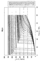
- FIG. 11 is a graph showing relationships between pressures and densities of light oil at respective temperatures.
- the fluid reforming apparatus of the present invention includes; a fuel reforming catalyst fixed to an inner wall of a flow channel; a fluid heating device provided in or outside of the flow channel; and catalyst temperature measuring devices provided in the flow channel and a pressure control device.
- the fluid heating device heats a fluid in the flow channel up to a target temperature at the time of reforming the fluid in the flow channel.
- the pressure control device pressurizes the fluid up to a target pressure. Then, the catalyst reforms such a fluid component.
- the pressure control device increases the target pressure when a difference between temperatures of the catalyst in a flow direction of the fluid, which are sensed by the catalyst temperature measuring devices, exceeds a predetermined value during a period while the fluid in the flow channel is being heated up to the target temperature.
- fuel reserved in a fuel tank is transferred to the flow channel in which the catalyst is disposed, and is reformed therein.
- the fuel in the flow channel is heated up to the target temperature while the pressure thereof is being controlled, whereby the fuel can be reformed while a temperature distribution difference of the fuel is being reduced from an upstream side of the fuel channel to a downstream side thereof.
- the fuel boils and becomes gaseous.
- thermal conductivity of the fuel is decreased radically.
- the fluid and/or the catalyst which exists between the gaseous portion and a heater (fluid heating device), is locally heated since heat does not conduct to the gaseous portion. Therefore, caulking of the fuel occurs, and sintering of the catalyst is accelerated.
- the caulking of the fuel and the sintering of the catalyst can be avoided by the fluid reforming apparatus of the present invention.
- heptane gasoline, light oil, liquefied natural gas, liquefied petroleum gas, biofuel or arbitrary combinations thereof are usable as the above-described fuel.
- gasoline containing methanol, hybrid fuel of the gas and the gasoline, and the like are usable.
- the above-described flow channel just needs to be a container capable of withstanding a pressure equal to or more than critical pressures of the fuel and a reactant to be described later.
- containers capable of withstanding 2 to 100 MPa for example, containers made of Inconel, Hastelloy and a titanium alloy are usable.
- the above-described flow channel is coupled to the fuel tank through a pipe, and has a feeding hole therein. Moreover, a discharge hole and another pipe, which are for supplying the reformed fuel to the outside, can also be arranged. It is desirable that such pipes be heat resistant and pressure resistant, and for example, pipes made of Inconel, Hastelloy and the titanium alloy are usable.
- the above-described pressure control device just needs to pressurize the fuel up to the critical pressures of the fuel and the reactant to be described later or more.
- the pressure control device devices which can pressurize the fuel up to 2 to 100 MPa, for example, high-pressure pumps are usable.
- the pressure control device includes a fluid pressure sensor, and for example, a usual corrosion-resistant high pressure sensor is usable.
- the above-described fluid heating device just needs to be able to heat the fluid up to a target reaction temperature.
- a device that can heat the fluid up to 200 to 600° C. for example, an electric heater and a heat exchanger are usable.
- thermocouples and platinum resistance thermometer sensors are usable.
- a temperature difference can be obtained between the inside of the catalyst coating layer and the place apart from the surface of the catalyst coating layer by the fixed distance. Note that, in the case where a distance between the inside of the catalyst coating layer and the place apart from the surface of the catalyst coating layer by the fixed distance is already known, a temperature gradient can be obtained between the inside and the place.
- the above-described catalyst is not particularly limited as long as it is suitable for a target reforming reaction.
- a reaction of reforming hydrocarbon such as heptane and the gasoline into hydrogen and carbon dioxide is mentioned.
- FIG. 7 is a perspective view of an embodiment of the fluid reforming apparatus of the present invention, in which a part of a heater is shown to be cut away.
- the fluid reforming apparatus of this embodiment includes: a high-pressure pump 10 ; a pressure sensor 20 ; a tubular heating chamber 30 in which a catalyst 1 is disposed on an inner wall; a heater 40 ; thermocouples 51 , 52 , 53 and 54 as examples of the catalyst temperature measuring devices; a pressure holding device 60 ; a fuel inlet portion 71 ; and a fuel outlet portion 72 .
- the heating chamber 30 corresponds to the above-described flow channel.
- the heating chamber 30 and the heater 40 cooperate with each other, and function as the fluid heating device.
- the high-pressure pump 10 , the pressure sensor 20 and the pressure holding device 60 cooperate with one another, and function as the pressure control device.
- a capillary, a pressure keeping valve and the like are usable as the pressure holding device 60 .
- the pressure holding device 60 may include a cooler according to needs.
- the fuel taken in from the fuel inlet portion 71 is fed into the heating chamber 30 heated by the heater 40 .
- the fuel thus fed is heated up to the target temperature in the heating chamber 30 , and the entirety or a part of the fuel is reformed by the catalyst.
- the fuel passes through the pressure holding device 60 , and is taken out from the fuel outlet portion 72 .
- the predicted temperatures are predicted temperatures of two thermocouples 51 and 52 arranged on an upstream side in a flow direction of the fluid, which are predicted from temperatures measured by temperature measuring spots 51 a and 52 a thereof, and from a temperature difference therebetween, and the measured temperatures are temperatures measured by temperature measuring spots 53 a and 54 a of two thermocouples 53 and 54 arranged on a downstream side in the flow direction.
- the high-pressure pump 10 , the pressure sensor 20 and the pressure holding device 60 cooperate with one another, and perform the pressure control for increasing the target pressure.
- FIG. 8 is a flowchart showing the example of the control flow in the above-described fluid reforming apparatus.
- Step S 1 a fluid temperature A 1 on the temperature measuring spot 51 a in the vicinity of the catalyst is sensed by the thermocouple 51 , and a fluid temperature A 2 on the temperature measuring spot 52 a is sensed by the thermocouple 52 . Then, the control flow proceeds to Step S 2 .
- Step S 2 a fluid temperature B 1 on the temperature measuring spot 53 a in the vicinity of the catalyst is sensed by the thermocouple 53 , and further, a fluid temperature B 2 on the temperature measuring spot 54 a is sensed by the thermocouple 54 . Then, the control flow proceeds to Step S 3 .
- Step S 3 a fluid pressure P is sensed by the pressure sensor 20 , and the control flow proceeds to Step S 4 .
- Step S 4 it is determined whether or not the pressure of the fluid is increased as instructed (to the target pressure). In the case where the pressure of the fluid is increased to the target pressure (in the case of YES), the control flow proceeds to Step S 5 . Meanwhile, in the case where the pressure of the fluid is not increased to the target pressure (in the case of NO), the control flow proceeds to Step S 11 .
- Step S 5 a temperature median value MA and a temperature difference DA are calculated from the sensed temperatures A 1 and A 2 , and the control flow proceeds to Step S 6 .
- the temperature median value MA is calculated in accordance with Expression 1
- the temperature difference DA is calculated in accordance with Expression 2.
- Step S 6 thermal conductivity TC and specific heat HC of the fluid are predicted from the sensed pressure P and the calculated temperature median value MA, and the control flow proceeds to Step S 7 .
- the thermal conductivity TC is calculated in accordance with Expression 3
- the specific heat HC is calculated in accordance with Expression 4.
- TC f ( MA,P ) [Math. 3]
- HC g ( MA,P ) [Math. 4]
- Step S 7 in accordance with Expression 5, a heat transfer amount Q is calculated from a product of the calculated temperature difference DA, the predicted thermal conductivity TC and a distance d 1 (a distance between the temperature measuring spot 51 a and the temperature measuring spot 52 a ). Moreover, in accordance with Expression 6, a transit time T obtained by dividing a distance d 2 between the two temperature measuring spots 51 a and 53 a by a linear velocity R of a center of the temperature measuring spots 51 a , 52 a , 53 a and 54 a is calculated. Next, in accordance with Expression 7, a temperature change predicted value DT obtained by dividing a product of the heat transfer amount Q and the transit time T by the specific heat HC of the fluid is calculated.
- a value is obtained by subtracting the sum of A 2 of the temperature measuring spot 52 a and DT from the value of B 2 of the temperature measuring spot 54 a in accordance with Expression 8.
- the control flow proceeds to Step S 8 .
- the control flow proceeds to Step S 1 .
- Q TC ⁇ DA/d 1 [Math. 5]
- T d 2 /R [Math. 6]
- DT Q/HC ⁇ T [Math. 7]
- Step S 8 a necessary pressure PN is calculated, and the control flow proceeds to Step S 9 .
- Step S 9 the pressure increase is instructed, and the control flow proceeds to Step S 10 .
- Step S 10 it is determined whether or not to stop the fluid reforming apparatus. In the case where it is determined to stop the fluid reforming apparatus (in the case of YES), the control flow proceeds to END. Meanwhile, in the case where it is determined not to stop the fluid reforming apparatus (in the case of NO) as a result of the determination in Step S 10 , the control flow proceeds to Step S 13 .
- Step S 11 it is determined whether or not the fluid reforming apparatus is damaged. In the case where it is determined that the fluid reforming apparatus is damaged (in the case of YES), the control flow proceeds to Step S 12 . Meanwhile, in the case where it is determined that the fluid reforming apparatus is not damaged (in the case of NO) as a result of the determination in Step S 11 , the control flow proceeds to Step S 13 .
- Step S 12 a warning is issued, the fluid reforming apparatus is stopped, and the control flow proceeds to END.
- Step S 13 the pressure is increased, and the control flow proceeds to Step S 1 .
- the two thermocouples 51 and 52 are provided on the upstream side of the heating chamber 30 of the flow channel, and the two thermocouples 53 and 54 are provided on the downstream side thereof. Then, when the temperature difference between the temperature measuring spot 51 a of the thermocouple 51 and the temperature measuring spot 53 a of the thermocouple 53 is a predetermined value or more, it is determined that the thermal conductivity is poor, that is, that the fuel becomes gaseous. Then, the pressure to the fuel is increased, whereby the control is performed so that the fuel can become liquid.
- the predetermined value just needs to be set depending on the type of the fuel, and specifically, can be set to be 5° C.
- the temperature measuring spots 51 a and 52 a of the thermocouples 51 and 52 on the upstream side and the temperature measuring spots 53 a and 54 a of the thermocouples 53 and 54 are provided at a center portion of the flow direction of the fluid in the heating chamber 30 .
- the positions of the temperature measuring spots of the thermocouples are not limited to the center of the heating chamber, and the temperature measuring spots may be provided at any positions in the heating chamber 30 as long as the temperature difference in the catalyst 1 can be measured.
- the pressure of the fuel is controlled so that the thermal conductivity of the fuel existing in the vicinity of the catalyst can be 0.06 W ⁇ m ⁇ 1 K ⁇ 1 or more. In such a way, the local heating is suppressed, whereby deterioration of the catalyst and the carbon deposition can be avoided.
- the thermal conductivity of the fuel is set at 0.06 W ⁇ m ⁇ 1 K ⁇ 1 or more by controlling the pressure thereof, whereby such local heating can be suppressed.
- the control of the above-described thermal conductivity be satisfied at least in a range of 1 mm or less from the surface of the catalyst coating layer.
- the pressure of the fuel at the critical pressure or more.
- the fuel does not become gaseous by maintaining the fuel at the critical pressure or more, and accordingly, the heat insulation state of the fuel can be avoided.
- the pressure of the fuel is increased to the critical pressure or more, whereby the local heating is suppressed, thus making it possible to avoid the deterioration of the catalyst and the occurrence the caulking.
- heptane the gasoline, the liquefied natural gas, the liquefied petroleum gas, the biofuel or the arbitrary combinations thereof are usable as the fuel.
- the pressure of the fuel at 180% or more of the critical pressure.
- the thermal conductivity of 0.06 W ⁇ m ⁇ 1 K ⁇ 1 or more can be maintained even if the fuel is heated up to around 300° C. as the temperature of the fuel.
- the fuel as a subject to be heated can be suppressed from becoming gaseous in a temperature range up to around 300° C., whereby the fuel can be reformed while avoiding the deterioration of the catalyst and the occurrence of the caulking.
- the pressure of the fuel at 300% or more of the critical pressure.
- the thermal conductivity of 0.06 W ⁇ m ⁇ 1 K ⁇ 1 or more can be maintained even if the fuel is heated up to around 500° C. as the temperature range.
- the fuel as the subject to be heated can be suppressed from becoming gaseous in the temperature range up to around 500° C., whereby the fuel can be reformed while avoiding the deterioration of the catalyst and the occurrence of the caulking.
- FIG. 6 is the simulation data of the temperature distribution in the case where the pressure of heptane was 3.0 MPa. Viewing the temperature distribution, it is understood that a cross-sectional temperature distribution of the pipe at a downstream terminal end thereof became uniform by setting the pressure of heptane at the above-described pressure. The heat of the pipe wall is transmitted to the fuel efficiently as described above, whereby the fuel in the vicinity of the pipe wall is not heated locally, and the carbon deposition can be avoided.
- FIG. 5 is the simulation data of the temperature distribution in the case where the pressure of heptane was 0.1 MPa. This pressure is not in a subcritical region or a supercritical region with respect to the critical pressure of heptane. In this pressure range, the cross-sectional temperature of the pipe is distributed over a considerably wide range at the downstream terminal end of the cylindrical pipe, and it is understood that the temperature is nonuniform particularly at a portion denoted by reference symbol B in the drawing.
- the fuel can be reformed while further adding the reactant into the flow channel. In such a way, the reforming reaction can be accelerated more. Furthermore, in the case where the decrease of the fuel density occurs, the pressure of the fuel is increased, whereby the local heating is suppressed, thus making it possible to avoid the deterioration of the catalyst.
- the above-described reactant for example, there are mentioned hydrocarbons, alcohols, water, oxygen, hydrogen peroxide, carbon dioxide or nitrogen oxide, and arbitrary combinations thereof.
- a pressure of such a mixture of the fuel and the reactant so that the thermal conductivity can be 0.06 W ⁇ m ⁇ 1 K ⁇ 1 or more.
- the pressure of the mixture is increased, whereby a density thereof is increased, the thermal conductivity is ensured, and the deterioration of the catalyst can be thereby avoided. Note that, even if such a mixed state is made, when the local thermal conductivity is decreased, there occurs a case where the catalyst temperature becomes extraordinarily high and the deterioration of the catalyst is accelerated.
- the pressure of the mixture in the flow channel at critical pressures of the fuel and the reactant or more.
- the fuel does not become gaseous, and accordingly, the heat insulation state can be avoided.
- the pressure of the fuel is increased to the critical pressure or more, whereby the local heating is suppressed, thus making it possible to avoid the deterioration of the catalyst and the occurrence of the caulking.
- FIG. 9 is a graph showing relationships between the pressures and densities of heptane at the respective temperatures.
- FIG. 10 is a graph showing relationships between the pressures and densities of the gasoline at the respective temperatures.
- FIG. 11 is a graph showing relationships between the pressures and densities of the light oil at the respective temperatures.
- the pressure of the fluid is adapted to be controlled so that the thermal conductivity thereof cannot be decreased. Accordingly, the local heating of the fluid in the flow channel is avoided, thus making is possible to suppress the carbon deposition (occurrence of the scorch and the caulking) and the sintering of the catalyst. In such a way, it becomes possible to reduce the region in which the fuel (fluid) is reformed, whereby the fluid reforming apparatus can be reduced in size.
Landscapes
- Engineering & Computer Science (AREA)
- Chemical & Material Sciences (AREA)
- Combustion & Propulsion (AREA)
- Mechanical Engineering (AREA)
- General Engineering & Computer Science (AREA)
- Chemical Kinetics & Catalysis (AREA)
- Hydrogen, Water And Hydrids (AREA)
- Fuel Cell (AREA)
Abstract
Description
DA=A1−A2 [Math. 2]
TC=f(MA,P) [Math. 3]
HC=g(MA,P) [Math. 4]
Q=TC×DA/d1 [Math. 5]
T=d2/R [Math. 6]
DT=Q/HC×T [Math. 7]
B2−(A2+DT) [Math. 8]
Claims (12)
Applications Claiming Priority (5)
| Application Number | Priority Date | Filing Date | Title |
|---|---|---|---|
| JP2006-213213 | 2006-08-04 | ||
| JP2006213213 | 2006-08-04 | ||
| JP2007198633A JP4798093B2 (en) | 2006-08-04 | 2007-07-31 | Fluid reforming apparatus and fluid reforming method using the same |
| JP2007-198633 | 2007-07-31 | ||
| PCT/JP2007/065680 WO2008016191A1 (en) | 2006-08-04 | 2007-08-03 | Fluid reforming device |
Publications (2)
| Publication Number | Publication Date |
|---|---|
| US20090252653A1 US20090252653A1 (en) | 2009-10-08 |
| US8623106B2 true US8623106B2 (en) | 2014-01-07 |
Family
ID=38997356
Family Applications (1)
| Application Number | Title | Priority Date | Filing Date |
|---|---|---|---|
| US12/373,406 Expired - Fee Related US8623106B2 (en) | 2006-08-04 | 2007-08-03 | Fluid reforming apparatus for maintaining thermal conductivity of a fluid in a flow channel |
Country Status (4)
| Country | Link |
|---|---|
| US (1) | US8623106B2 (en) |
| EP (1) | EP2048347B1 (en) |
| JP (1) | JP4798093B2 (en) |
| WO (1) | WO2008016191A1 (en) |
Cited By (9)
| Publication number | Priority date | Publication date | Assignee | Title |
|---|---|---|---|---|
| US20130000275A1 (en) * | 2011-06-30 | 2013-01-03 | Mark Vincent Scotto | Engine systems and methods of operating an engine |
| WO2013177468A2 (en) | 2012-05-24 | 2013-11-28 | Isis Pharmaceuticals, Inc. | Methods and compositions for modulating apolipoprotein(a) expression |
| WO2013177248A2 (en) | 2012-05-22 | 2013-11-28 | Isis Pharmaceuticals, Inc. | Modulation of enhancer rna mediated gene expression |
| WO2014059238A2 (en) | 2012-10-11 | 2014-04-17 | Isis Pharmaceuticals Inc | Modulation of androgen receptor expression |
| WO2014153236A1 (en) | 2013-03-14 | 2014-09-25 | Isis Pharmaceuticals, Inc. | Compositions and methods for modulating tau expression |
| US9118048B2 (en) | 2009-09-04 | 2015-08-25 | Lg Fuel Cell Systems Inc. | Engine systems and methods of operating an engine |
| US9178235B2 (en) | 2009-09-04 | 2015-11-03 | Lg Fuel Cell Systems, Inc. | Reducing gas generators and methods for generating a reducing gas |
| WO2017004261A1 (en) | 2015-06-29 | 2017-01-05 | Ionis Pharmaceuticals, Inc. | Modified crispr rna and modified single crispr rna and uses thereof |
| EP3556859A1 (en) | 2011-08-11 | 2019-10-23 | Ionis Pharmaceuticals, Inc. | Selective antisense compounds and uses thereof |
Families Citing this family (2)
| Publication number | Priority date | Publication date | Assignee | Title |
|---|---|---|---|---|
| US9209595B2 (en) * | 2014-01-31 | 2015-12-08 | Asml Netherlands B.V. | Catalytic conversion of an optical amplifier gas medium |
| JP6624583B1 (en) * | 2019-06-14 | 2019-12-25 | モーターマックス株式会社 | Member for fuel efficiency improvement device and fuel efficiency improvement device |
Citations (19)
| Publication number | Priority date | Publication date | Assignee | Title |
|---|---|---|---|---|
| EP0022876A1 (en) | 1978-12-28 | 1981-01-28 | Nissan Motor Co., Ltd. | Starter for alcohol engine |
| EP0032003A1 (en) | 1979-12-27 | 1981-07-15 | Aeci Limited | A device for converting alcohols to ethers and methods of running and of modifying a compression ignition engine to enable use therein of an alcohol/ether fuel |
| JPS61135974A (en) | 1984-11-30 | 1986-06-23 | ダブコ マニユフアクチユアリング コ−ポレ−シヨン | Fuel feeder for heating fuel |
| US4600825A (en) | 1981-06-03 | 1986-07-15 | Walter Blazejovsky | Electrically heated diesel engine fuel conveying system |
| US4807584A (en) | 1984-11-30 | 1989-02-28 | Davco Manufacturing Corp. | Fuel tank heating system |
| EP0419743A1 (en) | 1989-09-29 | 1991-04-03 | Her Majesty The Queen In Right Of New Zealand | Fuel supply and control system for compression ignition engines |
| US5237975A (en) | 1992-10-27 | 1993-08-24 | Ford Motor Company | Returnless fuel delivery system |
| US5799867A (en) | 1994-08-08 | 1998-09-01 | Yamaha Hatsudoki Kabushiki Kaisha | Engine-driven heat pump apparatus and method for stable operation of heat pump |
| US5927087A (en) | 1994-11-29 | 1999-07-27 | Ishikawa; Atuyumi | Refrigerating cycle |
| US6430949B2 (en) | 2000-04-19 | 2002-08-13 | Denso Corporation | Heat-pump water heater |
| US6561017B1 (en) | 2001-12-04 | 2003-05-13 | Dana Corporation | Tire inflation method |
| US20030159354A1 (en) * | 1996-10-30 | 2003-08-28 | Edlund David J. | Fuel processing system |
| JP2004162586A (en) | 2002-11-12 | 2004-06-10 | Toyota Motor Corp | Fuel supply device |
| JP2004257334A (en) | 2003-02-27 | 2004-09-16 | Nissan Motor Co Ltd | Fuel supply method and fuel supply device for internal combustion engine |
| US20040265225A1 (en) * | 2003-06-25 | 2004-12-30 | Watson Junko M. | Steam reforming methods and catalysts |
| JP2005180222A (en) | 2003-12-16 | 2005-07-07 | Toyota Motor Corp | Alcohol blended fuel engine |
| JP2006183469A (en) | 2004-12-24 | 2006-07-13 | Denso Corp | Fuel injector |
| US20060156627A1 (en) * | 2003-06-27 | 2006-07-20 | Ultracell Corporation | Fuel processor for use with portable fuel cells |
| US20070028602A1 (en) * | 2005-07-27 | 2007-02-08 | Dalla Betta Ralph A | Methods and systems for controlling internal combustion engines |
Family Cites Families (2)
| Publication number | Priority date | Publication date | Assignee | Title |
|---|---|---|---|---|
| JP2006213213A (en) | 2005-02-04 | 2006-08-17 | Jtekt Corp | Variable transmission ratio steering device |
| JP4783637B2 (en) | 2006-01-24 | 2011-09-28 | 本田技研工業株式会社 | Air conditioning method, air conditioning equipment, and control method of the air conditioning equipment |
-
2007
- 2007-07-31 JP JP2007198633A patent/JP4798093B2/en not_active Expired - Fee Related
- 2007-08-03 WO PCT/JP2007/065680 patent/WO2008016191A1/en not_active Ceased
- 2007-08-03 US US12/373,406 patent/US8623106B2/en not_active Expired - Fee Related
- 2007-08-03 EP EP07792326A patent/EP2048347B1/en not_active Not-in-force
Patent Citations (20)
| Publication number | Priority date | Publication date | Assignee | Title |
|---|---|---|---|---|
| EP0022876A1 (en) | 1978-12-28 | 1981-01-28 | Nissan Motor Co., Ltd. | Starter for alcohol engine |
| EP0032003A1 (en) | 1979-12-27 | 1981-07-15 | Aeci Limited | A device for converting alcohols to ethers and methods of running and of modifying a compression ignition engine to enable use therein of an alcohol/ether fuel |
| US4600825A (en) | 1981-06-03 | 1986-07-15 | Walter Blazejovsky | Electrically heated diesel engine fuel conveying system |
| JPS61135974A (en) | 1984-11-30 | 1986-06-23 | ダブコ マニユフアクチユアリング コ−ポレ−シヨン | Fuel feeder for heating fuel |
| US4807584A (en) | 1984-11-30 | 1989-02-28 | Davco Manufacturing Corp. | Fuel tank heating system |
| EP0419743A1 (en) | 1989-09-29 | 1991-04-03 | Her Majesty The Queen In Right Of New Zealand | Fuel supply and control system for compression ignition engines |
| US5237975A (en) | 1992-10-27 | 1993-08-24 | Ford Motor Company | Returnless fuel delivery system |
| DE4335866A1 (en) | 1992-10-27 | 1994-04-28 | Ford Werke Ag | Non-return fuel delivery system |
| US5799867A (en) | 1994-08-08 | 1998-09-01 | Yamaha Hatsudoki Kabushiki Kaisha | Engine-driven heat pump apparatus and method for stable operation of heat pump |
| US5927087A (en) | 1994-11-29 | 1999-07-27 | Ishikawa; Atuyumi | Refrigerating cycle |
| US20030159354A1 (en) * | 1996-10-30 | 2003-08-28 | Edlund David J. | Fuel processing system |
| US6430949B2 (en) | 2000-04-19 | 2002-08-13 | Denso Corporation | Heat-pump water heater |
| US6561017B1 (en) | 2001-12-04 | 2003-05-13 | Dana Corporation | Tire inflation method |
| JP2004162586A (en) | 2002-11-12 | 2004-06-10 | Toyota Motor Corp | Fuel supply device |
| JP2004257334A (en) | 2003-02-27 | 2004-09-16 | Nissan Motor Co Ltd | Fuel supply method and fuel supply device for internal combustion engine |
| US20040265225A1 (en) * | 2003-06-25 | 2004-12-30 | Watson Junko M. | Steam reforming methods and catalysts |
| US20060156627A1 (en) * | 2003-06-27 | 2006-07-20 | Ultracell Corporation | Fuel processor for use with portable fuel cells |
| JP2005180222A (en) | 2003-12-16 | 2005-07-07 | Toyota Motor Corp | Alcohol blended fuel engine |
| JP2006183469A (en) | 2004-12-24 | 2006-07-13 | Denso Corp | Fuel injector |
| US20070028602A1 (en) * | 2005-07-27 | 2007-02-08 | Dalla Betta Ralph A | Methods and systems for controlling internal combustion engines |
Non-Patent Citations (3)
| Title |
|---|
| K. Oshihara et al., USPTO Notice of Allowance, U.S. Appl. No. 12/373,411, Nov. 29, 2011, 8 pgs. |
| K. Oshihata et al., USPTO Non-Final Office Action, U.S. Appl. No. 12/373,411, Jun. 9, 2011, 10 pgs. |
| U.S. Appl. No. 12/373,411, filed Jan. 12, 2008, Oshihara et al. |
Cited By (11)
| Publication number | Priority date | Publication date | Assignee | Title |
|---|---|---|---|---|
| US9118048B2 (en) | 2009-09-04 | 2015-08-25 | Lg Fuel Cell Systems Inc. | Engine systems and methods of operating an engine |
| US9178235B2 (en) | 2009-09-04 | 2015-11-03 | Lg Fuel Cell Systems, Inc. | Reducing gas generators and methods for generating a reducing gas |
| US20130000275A1 (en) * | 2011-06-30 | 2013-01-03 | Mark Vincent Scotto | Engine systems and methods of operating an engine |
| US9140220B2 (en) * | 2011-06-30 | 2015-09-22 | Lg Fuel Cell Systems Inc. | Engine systems and methods of operating an engine |
| US10087895B2 (en) | 2011-06-30 | 2018-10-02 | Lg Fuel Cell Systems Inc. | Engine systems that are supplied with reformed fuel |
| EP3556859A1 (en) | 2011-08-11 | 2019-10-23 | Ionis Pharmaceuticals, Inc. | Selective antisense compounds and uses thereof |
| WO2013177248A2 (en) | 2012-05-22 | 2013-11-28 | Isis Pharmaceuticals, Inc. | Modulation of enhancer rna mediated gene expression |
| WO2013177468A2 (en) | 2012-05-24 | 2013-11-28 | Isis Pharmaceuticals, Inc. | Methods and compositions for modulating apolipoprotein(a) expression |
| WO2014059238A2 (en) | 2012-10-11 | 2014-04-17 | Isis Pharmaceuticals Inc | Modulation of androgen receptor expression |
| WO2014153236A1 (en) | 2013-03-14 | 2014-09-25 | Isis Pharmaceuticals, Inc. | Compositions and methods for modulating tau expression |
| WO2017004261A1 (en) | 2015-06-29 | 2017-01-05 | Ionis Pharmaceuticals, Inc. | Modified crispr rna and modified single crispr rna and uses thereof |
Also Published As
| Publication number | Publication date |
|---|---|
| EP2048347A4 (en) | 2012-04-04 |
| US20090252653A1 (en) | 2009-10-08 |
| JP2008057529A (en) | 2008-03-13 |
| JP4798093B2 (en) | 2011-10-19 |
| EP2048347A1 (en) | 2009-04-15 |
| WO2008016191A1 (en) | 2008-02-07 |
| EP2048347B1 (en) | 2013-01-02 |
Similar Documents
| Publication | Publication Date | Title |
|---|---|---|
| US8623106B2 (en) | Fluid reforming apparatus for maintaining thermal conductivity of a fluid in a flow channel | |
| JP5325403B2 (en) | Starting method of fuel cell system | |
| JP5214230B2 (en) | Starting method of fuel cell system | |
| AU2014346740B2 (en) | Multi-tubular chemical reactor with igniter for initiation of gas phase exothermic reactions | |
| KR19990082090A (en) | A water generation method, a reaction furnace for generating water, a temperature control method of a reaction furnace for generating water, and a method of forming a platinum-coated catalyst layer | |
| JP2009295380A (en) | Shutdown method of indirect internal reforming solid oxide fuel cell | |
| JP5325666B2 (en) | Method for stopping indirect internal reforming solid oxide fuel cell | |
| Davieau et al. | The effect of geometry on reactor performance in the steam-reformation process | |
| JP2010044909A (en) | Shutdown method of indirect internally reformed solid oxide fuel cell | |
| WO2010117033A1 (en) | Method of stopping indirect internal reforming solid oxide fuel cell | |
| JP5469440B2 (en) | Method for stopping indirect internal reforming solid oxide fuel cell | |
| JP5461834B2 (en) | Method for stopping indirect internal reforming solid oxide fuel cell | |
| JP5325641B2 (en) | Method for stopping indirect internal reforming solid oxide fuel cell | |
| US8155782B2 (en) | Fluid heating apparatus | |
| KR20250084958A (en) | Method for carrying out chemical reactions and reactor arrangement | |
| JP5325662B2 (en) | Method for stopping indirect internal reforming solid oxide fuel cell | |
| Hirata et al. | Hydrogen production by a steam-reformer for heavy hydrocarbons | |
| JP2006160547A (en) | Fuel reformer | |
| JP2009195839A (en) | Fluid reforming apparatus and fluid reforming method using the same | |
| JP7320321B2 (en) | Multi-tubular chemical reactor with igniter for gas phase exothermic reaction initiation | |
| CA3148487C (en) | Multi-tubular chemical reactor with igniter for initiation of gas phase exothermic reactions | |
| JP5325660B2 (en) | Method for stopping indirect internal reforming solid oxide fuel cell | |
| JP2010287328A (en) | Method for stopping indirect internal reforming solid oxide fuel cell |
Legal Events
| Date | Code | Title | Description |
|---|---|---|---|
| AS | Assignment |
Owner name: NISSAN MOTOR CO., LTD., JAPAN Free format text: ASSIGNMENT OF ASSIGNORS INTEREST;ASSIGNORS:OSHIHARA, KENZO;YAMAGUCHI, RYUUTA;REEL/FRAME:022094/0478;SIGNING DATES FROM 20081117 TO 20081120 Owner name: NISSAN MOTOR CO., LTD., JAPAN Free format text: ASSIGNMENT OF ASSIGNORS INTEREST;ASSIGNORS:OSHIHARA, KENZO;YAMAGUCHI, RYUUTA;SIGNING DATES FROM 20081117 TO 20081120;REEL/FRAME:022094/0478 |
|
| FEPP | Fee payment procedure |
Free format text: PAYOR NUMBER ASSIGNED (ORIGINAL EVENT CODE: ASPN); ENTITY STATUS OF PATENT OWNER: LARGE ENTITY |
|
| FEPP | Fee payment procedure |
Free format text: MAINTENANCE FEE REMINDER MAILED (ORIGINAL EVENT CODE: REM.) |
|
| LAPS | Lapse for failure to pay maintenance fees |
Free format text: PATENT EXPIRED FOR FAILURE TO PAY MAINTENANCE FEES (ORIGINAL EVENT CODE: EXP.) |
|
| STCH | Information on status: patent discontinuation |
Free format text: PATENT EXPIRED DUE TO NONPAYMENT OF MAINTENANCE FEES UNDER 37 CFR 1.362 |
|
| FP | Lapsed due to failure to pay maintenance fee |
Effective date: 20180107 |