US8604645B2 - Supply arrangement, supply unit and method for supplying an electronic unit - Google Patents
Supply arrangement, supply unit and method for supplying an electronic unit Download PDFInfo
- Publication number
- US8604645B2 US8604645B2 US12/808,148 US80814810A US8604645B2 US 8604645 B2 US8604645 B2 US 8604645B2 US 80814810 A US80814810 A US 80814810A US 8604645 B2 US8604645 B2 US 8604645B2
- Authority
- US
- United States
- Prior art keywords
- voltage
- supply
- unit
- supply unit
- switching element
- Prior art date
- Legal status (The legal status is an assumption and is not a legal conclusion. Google has not performed a legal analysis and makes no representation as to the accuracy of the status listed.)
- Expired - Fee Related, expires
Links
Images


Classifications
-
- H—ELECTRICITY
- H02—GENERATION; CONVERSION OR DISTRIBUTION OF ELECTRIC POWER
- H02J—ELECTRIC POWER NETWORKS; CIRCUIT ARRANGEMENTS OR SYSTEMS FOR SUPPLYING OR DISTRIBUTING ELECTRIC POWER; SYSTEMS FOR STORING ELECTRIC ENERGY
- H02J3/00—Circuit arrangements for AC mains or AC distribution networks
- H02J3/12—Arrangements for adjusting voltage in AC networks by changing a characteristic of the network load
- H02J3/14—Arrangements for adjusting voltage in AC networks by changing a characteristic of the network load by switching loads on to, or off from, the networks, e.g. progressively balanced loading
-
- H—ELECTRICITY
- H02—GENERATION; CONVERSION OR DISTRIBUTION OF ELECTRIC POWER
- H02J—ELECTRIC POWER NETWORKS; CIRCUIT ARRANGEMENTS OR SYSTEMS FOR SUPPLYING OR DISTRIBUTING ELECTRIC POWER; SYSTEMS FOR STORING ELECTRIC ENERGY
- H02J2207/00—Details of circuit arrangements for charging or discharging batteries or supplying loads from batteries
- H02J2207/10—Control circuit supply, e.g. means for supplying power to the control circuit
-
- Y—GENERAL TAGGING OF NEW TECHNOLOGICAL DEVELOPMENTS; GENERAL TAGGING OF CROSS-SECTIONAL TECHNOLOGIES SPANNING OVER SEVERAL SECTIONS OF THE IPC; TECHNICAL SUBJECTS COVERED BY FORMER USPC CROSS-REFERENCE ART COLLECTIONS [XRACs] AND DIGESTS
- Y02—TECHNOLOGIES OR APPLICATIONS FOR MITIGATION OR ADAPTATION AGAINST CLIMATE CHANGE
- Y02B—CLIMATE CHANGE MITIGATION TECHNOLOGIES RELATED TO BUILDINGS, e.g. HOUSING, HOUSE APPLIANCES OR RELATED END-USER APPLICATIONS
- Y02B70/00—Technologies for an efficient end-user side electric power management and consumption
- Y02B70/30—Systems integrating technologies related to power network operation and communication or information technologies for improving the carbon footprint of the management of residential or tertiary loads, i.e. smart grids as climate change mitigation technology in the buildings sector, including also the last stages of power distribution and the control, monitoring or operating management systems at local level
- Y02B70/3225—Demand response systems, e.g. load shedding, peak shaving
-
- Y—GENERAL TAGGING OF NEW TECHNOLOGICAL DEVELOPMENTS; GENERAL TAGGING OF CROSS-SECTIONAL TECHNOLOGIES SPANNING OVER SEVERAL SECTIONS OF THE IPC; TECHNICAL SUBJECTS COVERED BY FORMER USPC CROSS-REFERENCE ART COLLECTIONS [XRACs] AND DIGESTS
- Y04—INFORMATION OR COMMUNICATION TECHNOLOGIES HAVING AN IMPACT ON OTHER TECHNOLOGY AREAS
- Y04S—SYSTEMS INTEGRATING TECHNOLOGIES RELATED TO POWER NETWORK OPERATION, COMMUNICATION OR INFORMATION TECHNOLOGIES FOR IMPROVING THE ELECTRICAL POWER GENERATION, TRANSMISSION, DISTRIBUTION, MANAGEMENT OR USAGE, i.e. SMART GRIDS
- Y04S20/00—Management or operation of end-user stationary applications or the last stages of power distribution; Controlling, monitoring or operating thereof
- Y04S20/20—End-user application control systems
- Y04S20/222—Demand response systems, e.g. load shedding, peak shaving
Definitions
- the invention relates to a supply arrangement, a supply unit, as well as a method for supplying an electronic unit, in which an electronic unit is supplied with power independently of the switching state of the switching element.
- an operating voltage with two potentials is applied to a series circuit consisting of a switching element and an electrical load.
- the electrical switching element which has at least a first and a second switching state, is conventionally implemented as a mechanical element.
- Switching states are understood here to mean the “ON” switching state and the “OFF” switching state, the load being electroconductively connected to the operating power potential in the “ON” switching state, and cut off from this operating power potential in the “OFF” state.
- the “OFF” switching state will be referred to below as the first switching state, I
- the “ON” switching state will be referred to below as the second switching state, II.
- An operating voltage is understood here as either a DC voltage or an AC voltage.
- the term operating voltage is largely equivalent in the present invention to the term network voltage. In the European area, a network voltage of 230 V with a 50 Hz sinusoidal alternating voltage is currently provided by the respective network operators.
- Switching elements are used for switching electrical loads in building technology, for example.
- the switching element generally switches only one conductor carrying a voltage or a current. This is predominantly the so-called L-conductor. L stands here for a line or live wire.
- a normally mechanically formed switching element 8 is used here for switching electrical loads 3 .
- the current-carrying conductor L is either connected to the load or cut off from the load.
- an electronic unit for continuous or stepwise variable supplying of a potential to an electrical load can additionally be integrated into the switching element in order to dim light, for instance.
- An electronic unit can also be a radio receiver that receives a radio signal or electromagnetic radiation in general for switching the switching element. Corresponding to the radio signal, switching signals are generated by the radio receiver which place the switching element in one state or the other. Additional functions of electronic units in a switching element are likewise conceivable.
- an electronic unit can also contain several units, such as a radio receiver, a dimming or regulating unit and/or a timer circuit.
- the electronic triggering unit of a relay that drives the mechanical part of the relay will also be considered an electronic unit below.
- N-conductor serves as a return conductor and as reference potential of the electronic units in a switching element.
- One object of the present invention is to provide a supply arrangement, a supply unit and a method for supplying an electronic unit with power, wherein only one conductor carrying a voltage or current in and out and one switching element are available.
- a supply arrangement comprising a switching element having a first and a second switching state; an operating voltage having a first and a second potential, wherein the switching element is connected to a first terminal with the second potential of the operating voltage; an electrical load, wherein the load is connected to a first terminal with the first potential; and a supply unit with the first input connected to the second potential, a second input connected to a terminal of the switching element, an output connected to a second terminal of the load and a supply output connected to an electronic unit, wherein the supply unit supplies the electronic unit with power independently of the respective switching state.
- an electronic unit can be a sensor element that is continuously supplied with power by the supply arrangement and generates alarm signals, a report signal and/or control signals. If the electronic unit is a motion detector, an infrared sensor for instance, then it is ensured by the continuous supply of power that a motion inside the effective range of the motion detector will be recognized independently of the switching state of the switching element.
- the term electronic unit here is not limited to a single unit; it can contain several units, for instance, a control circuit, a timer circuit and/or a radio receiver circuit.
- the electronic units can in part shift the switching element into a different switching state and additionally contain other electronic units.
- the supply unit has a parallel voltage supply and the parallel voltage supply supplies the electronic unit with power as soon as the switching element is in switching state I, i.e., the switching element is open, it is guaranteed that a voltage supply by the parallel voltage supply unit is enabled. Due to the prevailing first switching state, the potential difference between the two switching element terminals the generation of a supply voltage is enabled.
- the supply unit further contains a series voltage supply unit
- the series voltage supply unit supplies the electronic unit with power as soon as the switching element is in a second switching state II, i.e., the switching element is closed.
- This series voltage supply unit which is advantageously situated in series between the switching element and the electrical load, will convert a current flow appearing due to the operation of the active load into a voltage drop.
- a shunt resistor, back-to-back connected diodes, a transformer or transistors are provided directly in the current flow, all of these elements converting parts of the current flow into a voltage drop.
- diodes additionally decouple the two voltage supply units from only other it is guaranteed that no reverse current or reverse voltage flows from the respectively active voltage supply unit to the respective other voltage supply unit, thereby destroying the other voltage supply unit.
- the supply unit produces a supply voltage in an advantageous manner, the supply voltage being defined relative to an autonomous reference potential.
- This autonomous reference potential is present inside the supply unit and is used only there and in the switching element. Since only one conductor carrying a current or voltage in and out is connected, a supply voltage is generated by this autonomous reference potential independently of the network potential.
- the parallel voltage supply unit is advantageously a buck converter, a stepdown converter or a transformer. These are distinguished by a very effective level of efficiency. This level of efficiency is particularly important if a voltage for the supply units is generated in the first switching state I of the switching element, and the electrical load is not to be operated.
- the active load is a tubular fluorescent lamp or an energy-saving lamp, for instance, which requires a defined ignition current in order to be turned on. If the parallel voltage supply element is not sufficiently effective or efficient, the generated current might be sufficiently high to be able to ignite the load even in the switched off switching state I.
- the electronic unit is a radio receiver or a dimmer or a control unit. If the electronic unit is a radio receiver, then a radio signal is transmitted to the radio receiver by means of remote control, for instance.
- the radio receiver generates an appropriate switching signal which causes the switching element to change from the first to the second switching state or vice versa.
- the radio receiver can also generate completely autonomous signals that are detached from the supply arrangement.
- additional control units are provided in the arrangement. Particularly with dimming switching units as electronic units, which not only have the effect of turning the switching unit on and off, but switch the network potential to the electronic load infinitely variably or stepwise, many switching states of the switching element are achieved.
- the switching element can be implemented in various ways. First, it can be a mechanical switch. Equally possible is an implementation as a transistor, a TRIAC, a relay or another known switching element.
- a so-called service switch can be arranged alongside the switching element preferably driven by electronic switching signals.
- This service switch is preferably a mechanical element and serves primarily as an additional operating possibility for a user to cut off the conductor carrying current or voltage actively from the electrical load.
- This service switch is preferably arranged in series between the operating voltage potential L and the supply arrangement. In some applications this service switch is prescribed by law or in order to satisfy a special standard. It also fulfills security aspects.
- the electronic unit is advantageously a timer switch.
- the switching element here is implemented in the form of a key. If the key is operated once, switching state II of the switching element is set. After expiration of a set time span in the timer circuit, switching state I is automatically set in the switching element.
- switching state I is automatically set in the switching element.
- the parallel voltage supply unit can be dispensed with, if appropriate.
- a method with which a supply arrangement as described above is operated is additionally provided.
- a network voltage potential is applied.
- This network voltage potential can be a DC voltage or an AC voltage.
- the invention is not limited by any ordinary network voltage level or a given type of network voltage.
- switching elements are likewise used to switch electrical loads, and a DC voltage is available as the supply voltage, such a supply arrangement is likewise conceivable.
- FIG. 1 shows a conventional switching element arrangement for connecting an electrical load according to prior art
- FIG. 2 a shows a first embodiment for supplying an electronic unit with power
- FIG. 2 b shows an alternative embodiment of the supply arrangement shown in FIG. 2 a
- FIG. 3 a shows a refinement of the embodiment shown in FIG. 2 a
- FIG. 3 b shows a refinement of the embodiment shown in FIG. 2 b
- FIG. 4 shows a refinement of the embodiment shown in FIG. 3 .
- FIG. 5 shows a first operating case I of the embodiment shown in FIG. 4 .
- FIG. 6 a second operating case II of the embodiment shown in FIG. 4 ,
- FIG. 7 shows a first embodiment of a series voltage supply unit from FIGS. 1-6 .
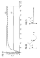
- FIG. 8 shows a voltage curve over time of the input and output voltage of a downstream linear voltage regulator for voltage smoothing from FIG. 7 ,
- FIG. 9 shows a voltage curve over time of the voltage drop across the TRIAC from FIG. 7 .
- FIG. 10 shows a refinement for noise reduction of the embodiment shown in FIG. 7 .
- FIG. 11 shows an alternative embodiment of the series voltage supply unit shown in FIGS. 1-6 .
- FIGS. 12-19 show voltage curves over time for different load or connection situations of the series voltage supply unit shown in FIG. 11 .
- FIG. 20 shows an alternative embodiment of a series voltage supply unit from FIGS. 1-6 .
- FIG. 21 shows a voltage curve over time of the input and output voltage of a linear voltage regulator from FIG. 21 ,
- FIG. 22 shows a voltage curve over time with indicated dual phase-angle control
- FIG. 23 shows a voltage curve over time with indicated single phase-angle control
- FIG. 24 shows an alternative embodiment of a series voltage supply unit from FIG. 11 .
- FIG. 1 was already described in the general part of the specification.
- an operating potential 2 with a first potential 201 , N and a second potential 202 , L is applied to a supply arrangement for supplying an electronic unit 7 with power independently of the switching state of a switching element 1 .
- Mechanical switching element 8 is shown here only in broken lines. Mechanical switching element 8 is not provided in the supply arrangement.
- a switching element 1 is represented with a first terminal 101 and a second terminal 102 .
- An electronic unit 7 is electroconductively connected to supply output 403 of supply unit 4 .
- Second terminal 102 of switching element 1 is electroconductively connected to second input 402 of supply unit 4 .
- First terminal 101 of switching element 1 is electroconductively connected to first input 401 of supply unit 4 .
- An electroconductive connection between second potential 202 of operating potential 2 and first input 401 of supply unit 4 , as well as an electroconductive connection of output 404 of supply unit 4 to second terminal 302 of electrical load 3 likewise exist.
- Electrical load 3 is additionally connected to a first terminal 301 with first potential 201 of operating voltage 2 .
- Operating voltage 2 is preferably a sinusoidal alternating voltage, in particular with the level of a network voltage.
- Switching element 8 is not provided and does not belong to the supply arrangement.
- the mechanical switching element should accordingly be replaced or integrated as a switching element 1 into the supply arrangement.
- Switching element 1 has at least a first and a second switching state I, II.
- case 1 is always understood to mean that switching element 1 is in the first switching state and is open
- case 2 is understood to mean that switching element 1 is in the second switching state and is closed.
- An electronic unit 7 is understood to be a unit which is to be supplied independently of the switching state of a switching element, with only one conductor carrying a current or voltage in and out.
- An electronic unit can contain several electronic units. Sensors, control units and/or alarm units can be provided as electronic units.
- an electronic unit 7 is fundamentally not limited by its function or its nature. The type of power supply for electronic unit 7 is likewise not limited. Electronic unit 7 can change the switching states I, II of switching element 1 .
- Electronic unit 7 is supplied with power in case 1 via second potential 202 which is present at first input 401 of supply unit 4 .
- the electronic circuit through electrical load 3 is closed via output 404 . Due to the voltage difference between input 401 and output 404 of supply unit 4 , a supply signal is made available to electronic unit 7 via supply output 403 .
- FIG. 2 b An alternative embodiment to the illustrated supply arrangement from FIG. 2 a is represented in FIG. 2 b . Since both embodiments are extremely similar, only the differences between FIGS. 2 a and 2 b will be discussed here.
- Switching element 1 has an additional supply input 103 , which is electroconductively connected to supply output 403 of supply unit 4 .
- Electronic unit 7 is situated inside switching element 1 .
- switching element 1 is understood to mean a switching element 1 driven by electrical signals and changing switching states I, II by means of electrical signals.
- the supply of power electronic units 7 via supply unit 4 is provided independently of the switching state of switching element 1 .
- electronic unit 7 generates a switching signal 104 with which switching element 1 changes a switching state.
- This electronic unit 7 is, for instance, a lamp dimmer circuit, control circuits for controlling light or a timer circuit, a radio receiver for remote controlling switching element 1 , the electronics of a relay, or any of various things.
- Switching element 1 can have more than two states, for instance, in which case an electric switching signal 104 sets the different switching states in switching element 1 .
- Switching element 1 fundamentally merely corresponds to the mechanism of a switching element.
- a control electronic unit or the like already corresponds to an electronic unit 7 .
- the mechanical switching elements of a bistable relay in the supply arrangement correspond, for instance, to the mechanism of switching element 1 .
- the electrical or electronic triggering as well as the electrical elements in the relay are to be viewed as an electronic unit 7 .
- at least one part of an electronic unit 7 is provided that changes the switching states I, II of the switching element by means of switching signals 104 .
- Other parts of electronic unit 7 can again be implemented as described under FIG. 2 a.
- a service switch 11 shown in broken lines, is optionally additionally inserted. This service switch is connected by a first terminal 110 to a current node A and by a second terminal 111 to a current node B.
- the electroconductive connection drawn in a solid line between current nodes A and B is omitted if surface switch 11 is included.
- Service switch 11 enables an additional possibility for switching electrical load 3 . Independently of the switching state I, II of switching element 1 , it is possible to cut off second potential 202 of operating voltage 2 at any time by means of service switch 11 which is, in particular, implemented mechanically. In some applications, such a service switch 11 is required for safety reasons or should be provided for reasons of user-friendliness. Service switch 11 can optionally be included in all embodiments.
- FIG. 3 a A refinement of the supply arrangement illustrated in FIG. 2 a is shown in FIG. 3 a . Only the differences between FIGS. 2 a and 3 a will be discussed below. Unlike FIG. 2 a , supply unit 4 is drawn in broken lines in this and the following figures and represented in more detail. Supply unit 4 is implemented in FIG. 3 a with a parallel voltage supply unit 5 and a series voltage supply unit 6 .
- FIG. 3 a An extensive functional description of FIG. 3 a is presented in the description of FIGS. 5 and 6 .
- FIG. 3 b A refinement of the embodiment from FIG. 2 b is shown in FIG. 3 b .
- the differences between FIGS. 2 b and 3 b correspond to the differences between FIGS. 2 a and 3 a , for which reason a detailed description is omitted at this point.
- electronic unit 7 is included as in FIGS. 2 b and 3 b .
- Electronic unit 7 preferably has an autonomous reference potential 10 .
- electronic unit 7 can likewise be included as in FIGS. 2 a and 3 b . A representation in this regard was omitted here.
- FIG. 4 A refinement of the embodiment represented in FIG. 3 b for supplying a switching element 1 with power is represented in FIG. 4 . Only the differences between FIGS. 3 b and 4 will be discussed below.
- two diodes 9 are represented. The latter serve to decouple the two voltage supply units 5 and 6 , and protect them from reverse current or reverse voltage.
- the two diodes have a first diode terminal 901 , also referred to as a cathode, and a second diode terminal 902 , also referred to as an anode.
- the two anode terminals 902 face the respective voltage unit 5 or 6 that is to be protected.
- an autonomous reference potential 10 is generated at voltage supply units 5 and 6 and is available to switching element 1 as well as electronic unit 7 .
- Autonomous is here understood to mean that reference potential 10 is independent with respect to operating voltage 2 , and is not relative to this operating voltage 2 or its potentials 201 and 202 .
- FIG. 4 An extensive functional description of FIG. 4 is presented in the description of FIGS. 5 and 6 .
- FIG. 4 The embodiment shown in FIG. 4 is sketched again in FIGS. 5 and 6 .
- switching states I and II of switching element 1 are represented.
- the part of the supply arrangement active for that state is drawn in solid lines, and the part of the supply arrangement which is inactive with respect to that switching state is drawn in broken lines.
- a distinction of cases regarding the two switching states I and II will now be performed.
- switching element 1 Since switching element 1 is open, there is no current flow between the two switching terminals 101 and 102 . Since electrical load 3 is not operated, a potential that is different from second potential 202 of operating voltage 2 is initially present at the second terminal 302 of load 3 and correspondingly at output 404 of parallel voltage supply 5 . This potential difference between 202 and 302 is used in parallel voltage supply unit 5 to prepare a supply voltage at supply output 403 of supply unit 4 .
- the parallel voltage supply unit has a very high efficiency. This is achieved especially by a highly efficient power supply/network adapter.
- Such supply units are, for instance, buck converters, stepdown converters or transformers.
- a glow lamp with an ignition voltage of roughly 80 V in the interior of the starter heats, by means of the current flowing through it, a bimetallic strip, which then interrupts the current flow through the heating coils and generates the ignition pulse via a choke.
- This current flow through this glow lamp also exists when a parallel voltage unit 5 is used in electrical load 3 , and causes a voltage drop both in the parallel voltage unit and in active load 3 . If the current through parallel voltage unit 5 is too high, the hot-start lamp will be ignited. If the voltage through the glow lamp is not greater than the ignition voltage, no current flows through the parallel power supply.
- Case II of the case distinction, in which switching element 1 is closed, is illustrated in FIG. 6 .
- an optionally inserted service switch 11 continues to be closed. If this is not taken into account, service switch 11 opens the circuit and the supply arrangement cannot be operated.
- the voltage Since the voltage is obtained from a series element, it is necessary to avoid high power losses in case of different, in particular, high electrical loads 3 . High power losses cause an excessive heat radiation in the supply arrangement and especially in supply unit 4 , which can possibly lead to loss of functionality, destruction or at least to a critical heating of supply unit 4 . If a sinusoidal alternating voltage is used as operating voltage 2 , two diodes connected back-to-back meaning antiparallel in general, or an NMOS power transistor with the reverse substrate diode used here can generate a voltage drop. The voltage drop can be smoothed by means of a linear voltage regulator.
- a TRIAC or a transformer is used in another embodiment variant. These embodiments of a series voltage supply unit 6 are described in FIGS. 7 , 10 , 11 and 20 .
- the solutions with a TRIAC or back-to-back NMOS transistors produce in principle a double-sided phase-angle control of operating voltage 2 , as shown in FIG. 22 .
- the operating voltage here is likewise a sinusoidal alternating voltage.
- a TRIAC is triggered only if the sine wave voltage has risen to a few volts. Triggering is understood here to mean becoming conductive. After the triggering there remains a residual voltage and thus a power loss.
- the bilateral sinusoidal section X 1 shown in FIG. 22 , up to the triggering of the TRIAC or, in case a single NMOS power transistor is used, the unilateral phase-angle control according to FIG. 23 is led off, for example, via diodes and charged onto capacitors.
- a simple, unregulated embodiment variant of series power supply unit 6 is shown in detail in FIG. 7 .
- the aforementioned TRIAC variant is shown.
- Terminals 402 , 403 , 404 and 10 serve for orientation from the previous figure descriptions.
- a TRIAC U 1 is arranged between input 402 of series voltage supply unit 6 and its output 404 . With regard to the functioning of TRIAC U 1 , the reader is referred to the description of FIGS. 6 and 22 .
- TRIAC U 1 such as a Q408L4 TRIAC, is connected in series to electrical load 3 .
- Diodes D 1 -D 4 conduct the voltage to a capacitor C 3 connected to reference a potential 10 . It will be charged by the shunted voltage.
- the charged voltage in C 3 is additionally provided to a linear voltage regulator U 2 , an LT1584 for example, as an input voltage U 21 . From input voltage U 21 , this voltage regulator U 2 generates a supply voltage U 22 that is made available via supply voltage output 403 to an electronic unit 7 .
- An equivalent ohmic load R 1 of electronic unit 7 is symbolically coupled to supply output 403 .
- This embodiment has a low component cost and low production costs.
- Resistor R 2 and diodes D 5 and D 6 serve here to adjust the trigger voltage of TRIAC U 1 .
- FIG. 8 The voltage curve over time of input U 21 and output U 22 of linear voltage regulator U 2 is shown in FIG. 8 . It is clearly visible that output voltage U 22 , which is fed as a supply voltage to electronic unit 7 , is very stable and smoothed.
- the circuit is operated at an electrical load 3 of 1100 W at 110 V, which demands a current of 10 A.
- Resistor R 1 has a resistance of 94 ohm.
- the voltage curve over time of the voltage drop of TRIAC U 1 is shown in FIG. 9 .
- the spikes in the voltage curve indicate the voltage drop of TRIAC U 1 , not triggered at this time. These peaks are conducted via diodes D 1 -D 4 to capacitor C 3 and charge it.
- a load 3 is operated that requires a current of 10 A.
- Resistor R 1 has a resistance of 94 ohm.
- FIG. 10 shows a refinement of series power supply unit 6 shown in FIG. 7 .
- Coils L 1 and L 2 and noise reduction capacitor C 1 are also used here to delay the switching edges of the voltage drop of plus and minus 2 V eff for a 10 A load 3 .
- FIG. 11 shows an example of an alternative embodiment of a series voltage supply unit 6 .
- a power NMOS transistor M 1 between lines 402 and 404 is used as a series element.
- a transistor M 1 with a very low RDS-ON is used, for example, an IRF6635.
- a phase-angle control X 1 of sinusoidal operating voltage 2 is used to generate the supply voltage. Due to the internal substrate diode, transistor M 1 is also in a position to process both semi-sinusoidal waves of operating voltage 2 ; see FIG. 23 .
- gate M 11 of power transistor M 1 is positive, a low voltage drop is observed between the drain and source terminals of transistor M 1 .
- the voltage at drain 402 of M 1 rises sharply, i.e., the transistor turns off.
- Gate M 11 is again raised by transistor Q 2 to a positive voltage level as soon as capacitor C 5 is charged.
- the transistor again turns on, i.e., conducts, by the positive voltage level at gate M 11 , and the voltage drop at drain terminal 402 is nearly 0 V.
- Diodes D 1 and D 6 preferably protect transistor M 1 against over-voltage and can be omitted if desired.
- Bipolar transistor Q 1 again discharges gate M 11 at the beginning of a new period of operating voltage 2 .
- M 1 thereby turns off and the voltage drop at drain 402 is a maximum.
- a maximal voltage drop is 5 V, for instance. If a higher voltage drop is generated under extreme circumstances, then a Zener diode D 8 limits the voltage to 20 V for instance.
- This alternative embodiment of a series voltage supply unit 6 requires few components, which are moreover economical. Fundamentally, considerably less energy is transformed into heat than, for instance, if a TRIAC, back-to-back diodes or shunt resistors are used as the series element.
- an electrical load 3 of 110 ohm is provided.
- the operating voltage is 110 V eff and thus produces a current of 1 A in the current loop.
- the resistance of R 1 is 94 ohm.
- the voltages between drain and source 402 of transistor M 1 and supply output voltage 403 at capacitor C 5 as well as sinusoidal voltage 201 - 202 are represented. Both voltages are relative to autonomous potential 10 . Also represented is the inverse operating voltage 2 . The origin of the signal curves is sufficiently described in FIG. 11 .
- FIG. 13 An electrical load 3 of 1100 ohm is provided in FIG. 13 . This is a comparatively low load of 11 W.
- the operating voltage is again 110 V eff and thus produces a current of 0.1 A in the current loop.
- the same voltage curves 402 , 403 and 2 as in FIG. 12 are represented, but with correspondingly longer turn-off times of transistor M 1 . It is recognizable that the maximal voltage drop at drain 402 of transistor M 1 is temporally longer per period of the operating voltage. This is necessary since capacitor C 5 requires a longer time to charge to the desired voltage level due to the lower load.
- Supply voltage 403 corresponds to the quotient of charge Q and the capacitance of C 5 .
- FIG. 14 An electrical load 3 of 11 ohm is provided in FIG. 14 .
- This is a comparatively large load of 1100 W at 110 V.
- the operating voltage is again 110 V eff and thus causes a current of 10 A in the current loop.
- the same voltage curves 402 , 403 , and 2 are represented as in FIG. 12 . It is recognizable that the maximum voltage drop at drain 402 of M 1 is temporally substantially shorter per period of the operating voltage than in FIGS. 12 and 13 . Since supply voltage 403 and the capacitance of C 5 are to be constant as in FIG. 13 , the charge must likewise be constant.
- FIG. 15 An electrical load 3 of 110 ohm is provided in FIG. 15 .
- the operating voltage is 110 V eff and thus produces a current of 1 A in the current loop.
- the resistance of R 1 is reduced to 50 ohm. Due to this higher load of electronic unit 7 , the voltage drop of the supply voltage at supply voltage output 403 is stronger during one period of operating voltage 2 , for which reason capacitor C 5 must be increased in comparison to FIG. 12 . Moreover, a higher supply output voltage is conceivable, which can be adjusted by means of Zener diode U 3 .
- the oscillogram shows the higher load in the lengthened 402 off-phase of transistor M 1 .
- FIG. 16 An electrical load 3 of 110 ohm is provided in FIG. 16 .
- the operating voltage is again 110 V eff and thus produces a current of 1 A in the current loop.
- the resistance of R 1 is now increased to 200 ohm. Due to this lower load of electronic unit 7 , the voltage drop of the supply voltage at supply voltage output 403 is lower during one period of operating voltage 2 , for which reason capacitor C 5 can be smaller in comparison to FIG. 12 . Moreover, a lower supply output voltage is conceivable, which can again be adjusted by means of Zener diode U 3 .
- the oscillogram shows the lower load in a narrower 402 off-phase of transistor M 1 .
- FIG. 17 An electrical load 3 of 11 ohm is provided in FIG. 17 . This is a comparatively large load of 1100 W.
- the operating voltage is again 110 V eff and thus produces a current of 10 A in the current loop.
- the resistance of R 1 is 94 ohm. This corresponds to a typical load of 35 mA at a supply voltage U 22 of 3.3 V.
- the section of the voltage drop between 402 and 404 at the drain of power transistor M 1 and operating voltage 2 is shown enlarged. The thermal power loss is less than 2 W in this case.
- the voltage curve over time at output capacitor C 5 is represented in FIG. 18 .
- a linear voltage regulator U 2 similar to that shown in FIGS. 7 and 10 is to be provided in series supply voltage unit 6 .
- a representation of the linear voltage regulator was omitted here.
- Output voltage U 22 of linear voltage regulator U 2 is supplied at supply output 403 to an electronic unit 7 . If input voltage U 21 of linear voltage regulator U 2 should be too low, it can be further adjusted by means of Zener diode U 3 .
- FIG. 19 An input voltage U 21 and an output voltage U 22 of a linear voltage regulator U 2 , not shown, is shown in FIG. 19 .
- the additional stabilization enables a lower residual ripple of the supply voltage at supply voltage output 403 .
- FIG. 20 An alternative embodiment of a series voltage supply unit 6 is represented in FIG. 20 .
- a transformer consisting of coils L 3 and L 4 is used.
- the transformer induces a voltage across diodes D 1 -D 4 , which is in turn supplied to a linear voltage regulator U 2 .
- An additional unit 7 is again arranged at output U 22 of linear voltage regulator U 2 .
- An electrical load 3 is represented by ohmic resistor R 9 .
- FIG. 21 A voltage curve over time of input voltage U 21 and output voltage U 22 is represented in FIG. 21 .
- the electrical load 3 here is 500 ohm.
- the transformer is used with a voltage ratio of 1:1. It is shown here that the transformer saturates as soon as the current through load 3 increases. A very small number of components is required in this embodiment variant.
- the sinusoidal components X 1 respectively used in phase-angle control are represented in FIGS. 22 and 23 .
- FIG. 24 An alternative embodiment of the series voltage supply unit 6 shown in FIG. 11 is represented in FIG. 24 .
- the differences between FIGS. 11 and 24 will now be discussed.
- an additional bipolar transistor Q 4 is inserted.
- the operating point of the transistor is set by means of resistors R 11 , R 12 and by U 4 .
- R 13 is added as a collector resistor for transistor Q 3 and as a series base resistor for transistor Q 1 .
- the sinusoidal operating voltage 2 is applied to terminals 402 and 404 .
- Zener diode U 3 is conductive in the positive half-wave of 2; transistor Q 3 is turned off, whereby transistor Q 1 becomes conductive.
- Q 1 pulls gate M 11 of transistor M 1 to autonomous reference potential 10 .
- Transistor M 1 is fundamentally turned off at a gate voltage of 0 V at terminal M 11 .
- the voltage between drain and source of M 1 is supplied via diode D 9 to linear voltage regulator U 2 .
- series voltage supply unit 403 provides a supply voltage to load R 1 .
- transistor Q 4 becomes conductive, whereby transistor Q 2 also becomes conductive.
- Transistor Q 2 pulls gate M 11 to a positive level above the threshold voltage of transistor M 1 . Thereby transistor M 1 becomes conductive.
- the voltage drop between drain and source of M 1 is nearly 0.
- M 1 is likewise conductive in the negative half-wave of 2, the only voltage drop between drain and source is the voltage drop of a diode.
- Electronic unit 7 in the illustrated figures is not only provided to generate an electrical switching signal 104 . It can generate or provide completely autonomous functions for elements outside the supply arrangement. It is not limited in its type and function.
- electronic unit 7 may be a radio receiver for using a radio switching element.
- an electrical switching signal 104 is generated in additional unit 7 that changes the switching state I, II of switching element 1 or can also fulfill a dimming function.
Landscapes
- Engineering & Computer Science (AREA)
- Power Engineering (AREA)
- Dc-Dc Converters (AREA)
- Circuit Arrangement For Electric Light Sources In General (AREA)
- Electronic Switches (AREA)
Applications Claiming Priority (4)
| Application Number | Priority Date | Filing Date | Title |
|---|---|---|---|
| DE200710060201 DE102007060201A1 (de) | 2007-12-14 | 2007-12-14 | Versorgungsanordnung, Versorgungseinheit und Verfahren zur Versorgung einer elektronischen Einheit |
| DE102007060201 | 2007-12-14 | ||
| DE102007060201.6 | 2007-12-14 | ||
| PCT/EP2007/064480 WO2009077011A1 (en) | 2007-12-14 | 2007-12-21 | Supply arrangement, supply unit and method for supplying an electronic unit |
Publications (2)
| Publication Number | Publication Date |
|---|---|
| US20100283328A1 US20100283328A1 (en) | 2010-11-11 |
| US8604645B2 true US8604645B2 (en) | 2013-12-10 |
Family
ID=40689454
Family Applications (1)
| Application Number | Title | Priority Date | Filing Date |
|---|---|---|---|
| US12/808,148 Expired - Fee Related US8604645B2 (en) | 2007-12-14 | 2007-12-21 | Supply arrangement, supply unit and method for supplying an electronic unit |
Country Status (4)
| Country | Link |
|---|---|
| US (1) | US8604645B2 (de) |
| EP (1) | EP2232688A1 (de) |
| DE (1) | DE102007060201A1 (de) |
| WO (1) | WO2009077011A1 (de) |
Families Citing this family (10)
| Publication number | Priority date | Publication date | Assignee | Title |
|---|---|---|---|---|
| US8304996B2 (en) * | 2010-02-04 | 2012-11-06 | Tyco Electronics Corporation | Photosensor circuits including a current amplifier |
| FR2956534A1 (fr) * | 2010-02-17 | 2011-08-19 | Cotherm Sa | Dispositif de maintien de l'alimentation d'un appareil electrique raccorde a un reseau electrique fonctionnant selon des periodes tarifaires par contacteur ou programmateur |
| MX2013001068A (es) | 2010-07-26 | 2013-03-18 | Tyco Electronics Corp | Circuito controlador que incluye un convertidor de energia de modo de conmutacion y un cierre automatico que usa el mismo. |
| CN102175979B (zh) * | 2010-12-31 | 2014-09-17 | 东莞市奇立电源有限公司 | 一种产品老化测试的节能方法及装置 |
| CN102297404B (zh) * | 2011-06-28 | 2013-04-24 | 鸿富锦精密工业(深圳)有限公司 | 灯管切换电路及灯管切换装置 |
| FR2977738B1 (fr) * | 2011-07-04 | 2015-01-16 | Mersen France Sb Sas | Systeme d'interruption de courant continu apte a ouvrir une ligne de courant continu a comportement inductif |
| DE102011080226B4 (de) * | 2011-08-01 | 2024-01-25 | Bayerische Motoren Werke Aktiengesellschaft | Fahrzeug mit einem Stromverteiler und einem Steuergerät |
| US8890050B2 (en) | 2011-11-21 | 2014-11-18 | Tyco Electronics Corporation | Photosensor circuits including a regulated power supply comprising a power circuit configured to provide a regulated power signal to a comparator of a pulse-width modulator |
| US20160241157A1 (en) * | 2015-02-12 | 2016-08-18 | General Electric Company | Small power harvesting methods for powering control devices using a single power line |
| WO2017084818A1 (en) | 2015-11-17 | 2017-05-26 | Philip Morris Products S.A. | Aerosol-generating system with self-activated electric heater |
Citations (6)
| Publication number | Priority date | Publication date | Assignee | Title |
|---|---|---|---|---|
| US4270058A (en) | 1979-07-25 | 1981-05-26 | Schornack Louis W | Power supply and control circuit for series connected controller |
| US5004972A (en) * | 1989-12-26 | 1991-04-02 | Honeywell Inc. | Integrated power level control and on/off function circuit |
| US5811963A (en) | 1994-10-11 | 1998-09-22 | Novitas Incorporated | Line powered DC power supply |
| US6356038B2 (en) | 1994-12-14 | 2002-03-12 | Richard A. Bishel | Microcomputer-controlled AC power switch controller and DC power supply method and apparatus |
| FR2848034A1 (fr) | 2002-11-29 | 2004-06-04 | Somfy Sas | Procede et dispositif d'alimentation du module electronique d'un dispositif de commande |
| US20060158171A1 (en) | 2005-01-18 | 2006-07-20 | Downey Walter J | Circuit for use with switched leg power supply |
-
2007
- 2007-12-14 DE DE200710060201 patent/DE102007060201A1/de not_active Withdrawn
- 2007-12-21 WO PCT/EP2007/064480 patent/WO2009077011A1/en not_active Ceased
- 2007-12-21 US US12/808,148 patent/US8604645B2/en not_active Expired - Fee Related
- 2007-12-21 EP EP20070858091 patent/EP2232688A1/de not_active Withdrawn
Patent Citations (6)
| Publication number | Priority date | Publication date | Assignee | Title |
|---|---|---|---|---|
| US4270058A (en) | 1979-07-25 | 1981-05-26 | Schornack Louis W | Power supply and control circuit for series connected controller |
| US5004972A (en) * | 1989-12-26 | 1991-04-02 | Honeywell Inc. | Integrated power level control and on/off function circuit |
| US5811963A (en) | 1994-10-11 | 1998-09-22 | Novitas Incorporated | Line powered DC power supply |
| US6356038B2 (en) | 1994-12-14 | 2002-03-12 | Richard A. Bishel | Microcomputer-controlled AC power switch controller and DC power supply method and apparatus |
| FR2848034A1 (fr) | 2002-11-29 | 2004-06-04 | Somfy Sas | Procede et dispositif d'alimentation du module electronique d'un dispositif de commande |
| US20060158171A1 (en) | 2005-01-18 | 2006-07-20 | Downey Walter J | Circuit for use with switched leg power supply |
Also Published As
| Publication number | Publication date |
|---|---|
| EP2232688A1 (de) | 2010-09-29 |
| DE102007060201A1 (de) | 2009-06-25 |
| WO2009077011A1 (en) | 2009-06-25 |
| US20100283328A1 (en) | 2010-11-11 |
Similar Documents
| Publication | Publication Date | Title |
|---|---|---|
| US8604645B2 (en) | Supply arrangement, supply unit and method for supplying an electronic unit | |
| US20240381506A1 (en) | Load control device for a light-emitting diode light source | |
| US7804200B2 (en) | Photosensor circuits including a switch mode power converter | |
| US7990070B2 (en) | LED power source and DC-DC converter | |
| AU2010203058B2 (en) | Switch mode power converter | |
| US6426597B2 (en) | Circuit arrangement for operating gas discharge lamps | |
| EP2347635B1 (de) | Fotosensorschaltungen mit einem schaltstromwandler | |
| US10462859B2 (en) | Clocked flyback converter circuit | |
| KR20050050674A (ko) | 용량성 연결된 전원 공급기 | |
| JP6534102B2 (ja) | 調光装置 | |
| US8575847B2 (en) | Control circuit of light-emitting element | |
| US8304996B2 (en) | Photosensor circuits including a current amplifier | |
| WO2018055990A1 (ja) | 調光装置の保護回路、及び調光装置 | |
| RU2343622C1 (ru) | Способ управления транзисторным ключом на тиристоре и устройство для его осуществления | |
| US20090244930A1 (en) | Electrical dc-dc power converter with magnetically coupled switch control circuit | |
| US6690150B2 (en) | Method and a system for producing a power supply voltage for controlling an electronic switch | |
| US8547029B2 (en) | Dimmable instant start ballast | |
| WO2023227456A1 (en) | Connected bulb rc latch optimized for low standby power | |
| HK40002528A (en) | Load control device for a light-emitting diode light source |
Legal Events
| Date | Code | Title | Description |
|---|---|---|---|
| AS | Assignment |
Owner name: ENOCEAN GMBH, GERMANY Free format text: ASSIGNMENT OF ASSIGNORS INTEREST;ASSIGNOR:EGGERT, HOLGER ALFONS;REEL/FRAME:024795/0586 Effective date: 20100503 |
|
| STCF | Information on status: patent grant |
Free format text: PATENTED CASE |
|
| FPAY | Fee payment |
Year of fee payment: 4 |
|
| MAFP | Maintenance fee payment |
Free format text: PAYMENT OF MAINTENANCE FEE, 8TH YR, SMALL ENTITY (ORIGINAL EVENT CODE: M2552); ENTITY STATUS OF PATENT OWNER: SMALL ENTITY Year of fee payment: 8 |
|
| FEPP | Fee payment procedure |
Free format text: MAINTENANCE FEE REMINDER MAILED (ORIGINAL EVENT CODE: REM.); ENTITY STATUS OF PATENT OWNER: SMALL ENTITY |
|
| LAPS | Lapse for failure to pay maintenance fees |
Free format text: PATENT EXPIRED FOR FAILURE TO PAY MAINTENANCE FEES (ORIGINAL EVENT CODE: EXP.); ENTITY STATUS OF PATENT OWNER: SMALL ENTITY |
|
| STCH | Information on status: patent discontinuation |
Free format text: PATENT EXPIRED DUE TO NONPAYMENT OF MAINTENANCE FEES UNDER 37 CFR 1.362 |
|
| FP | Lapsed due to failure to pay maintenance fee |
Effective date: 20251210 |