US8588974B2 - Work apparatus and calibration method for the same - Google Patents
Work apparatus and calibration method for the same Download PDFInfo
- Publication number
- US8588974B2 US8588974B2 US12/641,246 US64124609A US8588974B2 US 8588974 B2 US8588974 B2 US 8588974B2 US 64124609 A US64124609 A US 64124609A US 8588974 B2 US8588974 B2 US 8588974B2
- Authority
- US
- United States
- Prior art keywords
- robot
- unit
- distance information
- work
- work unit
- Prior art date
- Legal status (The legal status is an assumption and is not a legal conclusion. Google has not performed a legal analysis and makes no representation as to the accuracy of the status listed.)
- Expired - Fee Related, expires
Links
Images

Classifications
-
- B—PERFORMING OPERATIONS; TRANSPORTING
- B25—HAND TOOLS; PORTABLE POWER-DRIVEN TOOLS; MANIPULATORS
- B25J—MANIPULATORS; CHAMBERS PROVIDED WITH MANIPULATION DEVICES
- B25J9/00—Programme-controlled manipulators
- B25J9/16—Programme controls
- B25J9/1679—Programme controls characterised by the tasks executed
- B25J9/1692—Calibration of manipulator
-
- G—PHYSICS
- G05—CONTROLLING; REGULATING
- G05B—CONTROL OR REGULATING SYSTEMS IN GENERAL; FUNCTIONAL ELEMENTS OF SUCH SYSTEMS; MONITORING OR TESTING ARRANGEMENTS FOR SUCH SYSTEMS OR ELEMENTS
- G05B19/00—Programme-control systems
- G05B19/02—Programme-control systems electric
- G05B19/18—Numerical control [NC], i.e. automatically operating machines, in particular machine tools, e.g. in a manufacturing environment, so as to execute positioning, movement or co-ordinated operations by means of programme data in numerical form
- G05B19/401—Numerical control [NC], i.e. automatically operating machines, in particular machine tools, e.g. in a manufacturing environment, so as to execute positioning, movement or co-ordinated operations by means of programme data in numerical form characterised by control arrangements for measuring, e.g. calibration and initialisation, measuring workpiece for machining purposes
-
- G—PHYSICS
- G06—COMPUTING OR CALCULATING; COUNTING
- G06T—IMAGE DATA PROCESSING OR GENERATION, IN GENERAL
- G06T1/00—General purpose image data processing
-
- G—PHYSICS
- G05—CONTROLLING; REGULATING
- G05B—CONTROL OR REGULATING SYSTEMS IN GENERAL; FUNCTIONAL ELEMENTS OF SUCH SYSTEMS; MONITORING OR TESTING ARRANGEMENTS FOR SUCH SYSTEMS OR ELEMENTS
- G05B2219/00—Program-control systems
- G05B2219/30—Nc systems
- G05B2219/37—Measurements
- G05B2219/37009—Calibration of vision system, camera, adapt light level
-
- G—PHYSICS
- G05—CONTROLLING; REGULATING
- G05B—CONTROL OR REGULATING SYSTEMS IN GENERAL; FUNCTIONAL ELEMENTS OF SUCH SYSTEMS; MONITORING OR TESTING ARRANGEMENTS FOR SUCH SYSTEMS OR ELEMENTS
- G05B2219/00—Program-control systems
- G05B2219/30—Nc systems
- G05B2219/37—Measurements
- G05B2219/37423—Distance, gap between tool and surface sensor
Definitions
- the present invention relates to a work apparatus such as a robot that performs work, and particularly relates to a calibration method for calibrating the optical-axis direction of a distance measurement unit that the work apparatus has, and an offset amount.
- a distance measurement unit distance sensor
- Patent Document 1 the end of a welding torch of a welding robot is caused to touch a reference position on a workpiece in teaching, and a laser illumination position of a laser sensor for distance measurement is caused to match with the reference position in teaching, thereby obtaining the optical-axis direction of the distance sensor and an offset amount. Further, in Patent Document 2, calibration is performed by causing a robot to touch a plurality of points on a plane jig whose world coordinates are known in teaching, and establishing correspondence between the result of three-dimensional measurement and the robot coordinate system.
- Patent Documents 1 and 2 disclose methods for calibration by manually moving a robot in teaching and causing the robot to touch a reference position.
- Patent Document 3 discloses that by placing the optical axis of a distance sensor so as to match the center axis of a robot hand, correspondence between the robot coordinate system and the distance sensor coordinate system is established, without calibration. This is a method for addressing the problem, through the position at which the sensor is placed.
- Patent Document 4 discloses that a plate having a marker whose position is known is attached to a robot arm, laser slit light from a projector placed in a global position is emitted on the plate, an image thereof is taken with a camera, and coordinate calibration is performed. Since the world coordinate position of the marker is determined by a robot command, correspondence between the image coordinates of the laser slit and the robot coordinates are decided.
- Patent Document 5 a tilted plate is rotated having a rotation axis at the same position as the design position of the distance sensor laser optical axis, and the angle of the optical axis relative to a designed value is calculated from the difference between measured values.
- This method requires a jig with which highly accurate operation and attachment accuracy are assured.
- Patent Document 6 the optical-axis direction of a camera mounted to an arm is obtained by moving the arm while maintaining a target in a working area so as to be in the image center using visual servoing.
- this conventional example only the optical-axis direction of the camera is obtained, and calculation for obtaining an offset amount relative to the robot hand is not referred to.
- Patent Document 4 the projector of laser slit light is placed in a global position, and accordingly a measurable area is limited. Further, in order to make the marker position of the plate attached to the robot arm known in the robot coordinate system, the marker position on the plate needs to be decided with high accuracy, and the attachment accuracy of the plate is also required.
- Patent Document 5 discloses a calibration method using a special jig, a jig that is created with high accuracy and operates with high accuracy is needed, and the jig also needs to be attached to an apparatus accurately. Such a jig is expensive, and furthermore, placement thereof is complicated.
- the present invention has been made in light of the above problems, and an object thereof is to contactlessly and automatically obtain a calibration parameter for a work unit and a distance measurement unit that a work apparatus has.
- a calibration method for a work apparatus comprising a moving unit configured to move a work unit to a work position, a distance information obtaining unit placed on the moving unit and configured to move together with the work unit, and an imaging apparatus fixed independently from the moving unit, the method comprising:
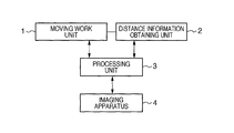
- FIG. 1 is a block diagram showing the schematic configuration of a work apparatus in an embodiment of the present invention.
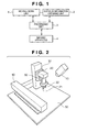
- FIG. 2 is a diagram showing an example of the configuration of the work apparatus according to an embodiment of the present invention.
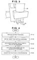
- FIG. 3 is a diagram illustrating a work reference point.
- FIG. 4 is a flowchart illustrating calibration processing in an embodiment of the present invention.
- FIGS. 5A and 5B are diagrams illustrating a calibration plate in an embodiment.
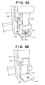
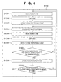
- FIG. 6 is a flowchart showing the details of work reference point target position calculation processing in a first embodiment.
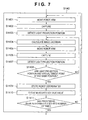
- FIG. 7 is a flowchart showing the details of light projection target position calculation processing in the first embodiment.
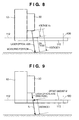
- FIG. 8 is a diagram illustrating a work reference plane and a bias.
- FIG. 9 is a diagram illustrating a calibration value in an embodiment.
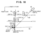
- FIG. 10 is a diagram showing the principle of calibration in an embodiment.
- FIG. 11 is a flowchart showing the details of light projection target position calculation processing in a second embodiment and a third embodiment.
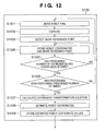
- FIG. 12 is a flowchart showing the details of work reference point target position calculation processing in a fourth embodiment.
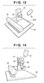
- FIG. 13 is a diagram illustrating calibration using a light projection plate in the third embodiment.
- FIG. 14 is a diagram showing the configuration of a work apparatus in a sixth embodiment.
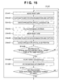
- FIG. 15 is a flowchart showing the details of light projection target position calculation processing in the sixth embodiment.
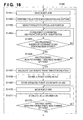
- FIG. 16 is a flowchart showing another procedure of light projection target position calculation processing in the sixth embodiment.
- FIG. 1 shows a basic configuration of an apparatus suitable for implementing the present invention.
- a moving work unit 1 is an apparatus that has an operation mechanism for movement in order to perform work, and specifically, is realized by an industrial robot arm, an automatic stage, an end effector placed thereon, and the like.
- the moving work unit 1 is provided with a work unit (a robot hand or the like) that actually performs work with respect to a work target, and a moving unit (a robot arm) that moves the work unit to a work position.
- a distance information obtaining unit 2 is physically connected to the moving work unit 1 , and its position changes in accordance with the movement of the moving work unit 1 .
- An imaging apparatus 4 is an apparatus for capturing a working area of the moving work unit 1 , and is fixed independently from the moving work unit 1 .
- a processing unit 3 is connected to the moving work unit 1 , the distance information obtaining unit 2 , and the imaging apparatus 4 , and is an apparatus for controlling each unit and performing desired calculation based on information obtained from each unit.
- the processing unit 3 is constituted by a personal computer or a programmable controller (hereinafter, referred to as a PC), a robot controller, or the like.
- FIG. 2 shows a specific configuration of an apparatus suitable for implementing the present invention in a first embodiment.
- FIG. 2 is a diagram showing an example of a configuration of a work apparatus in the first embodiment.
- a movable robot arm 10 is fixed to a working area 50 .
- a hand base plate 31 is placed in a portion where an end effector of the robot arm 10 is attached, and a robot hand 20 is fixed to the hand base plate 31 . These correspond to the moving work unit 1 shown in FIG. 1 .
- a distance sensor 30 is fixed to the hand base plate 31 , and when the end effector of the robot arm 10 moves, the end effector operates such that the relative positional relationship between the robot hand 20 and the distance sensor 30 does not change via the hand base plate 31 .
- the distance sensor 30 is a sensor using existing technology for illuminating an object to be measured with laser light emitted downward, and outputting a voltage value that is proportional to the distance by using a PSD or the like to detect the position of a luminescent spot obtained by the laser being diffusely reflected by the surface of the measurement target.
- the distance sensor 30 corresponds to the distance information obtaining unit 2 shown in FIG. 1 .
- the distance sensor 30 is connected to a PC (not shown) via an A/D converting board or the like (not shown), and the PC can monitor a value measured by the distance sensor.
- the robot arm 10 shown in FIG. 2 is an XYZ type robot, the work apparatus of the present invention is not limited to this configuration, and a robot having another configuration, such as a scalar type robot or a multi-jointed robot, for example, may be used.
- the robot hand 20 is provided with fingers 21 and 22 for holding an object. Although the robot hand 20 is drawn with two fingers here, a robot hand constituted from three or more fingers may be used. Further, if the operation purpose of the robot is not holding an object, a robot hand provided with a work unit having a configuration other than a finger, such as a welding torch, at the end may be used.
- the robot arm 10 is connected to a robot controller (not shown), and operates in accordance with an operation signal from the robot controller.
- the PC and the robot controller correspond to the processing unit 3 shown in FIG. 1 .
- a camera 40 corresponding to the imaging apparatus 4 is placed in the space above the robot, and captures the working area 50 .
- the camera 40 is connected to the PC described above, and prescribed processing is performed on images acquired from the camera 40 using a program that operates on the PC.
- the robot controller and the PC are connected, and a command can be transmitted to the robot arm 10 from the robot controller in accordance with instructions from the PC.
- FIG. 3 is a diagram illustrating an example of a work reference point of the work apparatus in the present embodiment.
- the middle position between the fingers 21 and 22 of the robot hand 20 needs to be matched with a target to be held. This middle position is defined as a work reference point.
- the work reference point is shown by reference numeral 100 . If the height of a target to be held is indefinite, a movement command for moving the work reference point 100 to a prescribed position needs to be given to the robot controller based on the distance obtained by the distance sensor 30 . In order to give a movement command as robot coordinates, the relative position between the distance sensor 30 and the work reference point 100 needs to be obtained.
- a user places a calibration plate 110 on the hand base plate 31 .
- a marker 111 whose center is in a position that matches the work reference point 100 is drawn on the calibration plate 110 .
- a work reference plane 112 is set to the calibration plate 110 in order to have illumination with the laser light emitted from the distance sensor 30 at the same height relative to the work reference point when the calibration plate 110 is placed.
- FIG. 5B calibration work is performed in a state in which the robot hand 20 is removed from the hand base plate 31 .
- the PC acquires a value measured by the distance sensor 30 , in a state in which the calibration plate 110 has been placed, and stores this as a bias voltage value in a storage device of the PC.
- the PC sets a virtual target point on the image plane of an image obtained from the camera 40 , and stores this in its storage device.
- the PC causes the robot arm 10 to operate such that the center position of the marker 111 of the calibration plate 110 , or in other words, the work reference point 100 comes closer to the virtual target point on the image obtained from the camera 40 . Then, the PC obtains a plurality of robot coordinates at which the work reference point 100 and the virtual target point match on the image, and the robot coordinate values at that time are stored in the storage device of the PC. In other words, the PC performs first obtaining processing for obtaining a plurality of coordinates (robot coordinates) of the moving unit (the moving work unit 1 ) at which the work reference point 100 of the work unit, and the virtual target point set in S 120 are caused to match on the image captured by the camera 40 .
- the user removes the calibration plate 110 from the hand base plate 31 .
- the PC causes the distance sensor 30 to emit a laser in the state in which the calibration plate 110 is removed, and captures, with the camera 40 , the diffuse reflection of the laser with which the working area 50 is illuminated, and detects the light projection position of the laser on the image.
- the PC causes the robot arm 10 to operate such that the detected light projection position comes closer to the virtual target point on the image.
- the PC obtains a plurality of robot coordinates at which the light projection position and the virtual target point match on the image, and stores these in its storage device, together with the voltage value output by the distance sensor 30 at each of the coordinates.
- the PC performs second obtaining processing for obtaining, on the image plane, a plurality of coordinates (robot coordinates) of the moving unit (the moving work unit 1 ) at which the light projection position of the distance sensor 30 and the virtual target point are caused to match, and a plurality of pieces of distance information from the distance sensor 30 at those positions.
- the PC calculates the relative positional relationship between the distance sensor 30 and the work reference point 100 as a calibration value based on the following that are obtained through the previous processes, and stores the result in its storage device:
- the PC causes the distance sensor 30 to emit a laser in a state in which the calibration plate 110 is attached, and measures the distance.
- the PC stores the output voltage obtained at this time in the storage device as a bias voltage V B .
- virtual target point setting processing S 120
- the PC defines a virtual target point at an arbitrary image coordinate position in the image obtained from the camera 40 , and stores this as coordinates x S in the storage device.
- FIG. 6 is a flowchart showing the details of work reference point target position calculation processing in the present embodiment.
- the PC fixes a Z coordinate value of a robot coordinate system to Z 1 , causes the robot arm 10 to move to the position of arbitrary coordinates (a value of X and Y coordinates) in the robot coordinate system (S 1301 ), and performs capture with the camera 40 (S 1302 ).
- the PC calculates the center position of the marker 111 on the calibration plate from the obtained image, and sets this as the detected position of the work reference point 100 (S 1303 ). Based on the captured result, the PC causes the robot arm 10 to move such that the work reference point 100 (the center of the marker 111 ) on the calibration plate 110 matches the virtual target point x S .
- the PC calculates an image Jacobian (S 1304 ) by calculating a movement vector of the work reference point 100 in an image coordinate system of an image captured by the camera 40 , with respect to a movement vector of the robot arm 10 in the robot coordinate system in the previous frame. Then, from a difference vector between the virtual target point x S and the work reference point 100 on the image, and the obtained image Jacobian, the PC causes the robot arm 10 to move in the direction in which the difference vector is smaller (S 1305 ).
- the PC fixes the Z coordinate value of the robot coordinate system to Z 2 , and causes the robot to move by performing similar processing to the above processing, such that the work reference point 100 matches the virtual target point x S (S 1301 to S 1308 ). Then, the PC stores the Z coordinate value as Z 2 , and the obtained robot coordinates as X H2 in the storage device (S 1309 ). After processing has been performed, as described above, a prescribed number of times (twice in this example) with a different Z coordinate value, work reference point target position calculation processing (S 130 ) ends (S 1310 ).
- FIG. 7 is a flowchart illustrating light projection target position calculation processing in the first embodiment.
- the calibration plate 110 is removed from the hand base plate 31 . Similar to work reference point target position calculation processing (S 130 ), the PC fixes the Z coordinate value of the robot coordinate system to Z 1 , and causes the robot arm 10 to move to the position of arbitrary coordinates (a value of X and Y coordinates) in the robot coordinate system (S 1401 ). Then, in the state in which the calibration plate is removed, the PC executes illumination with the laser by the distance sensor 30 , and capture with the camera 40 (S 1402 ), and detects the light projection position where the floor surface of the working area 50 is illuminated with the laser (S 1403 ).
- the PC causes the robot arm 10 to move such that the detected light projection position is projected on the virtual target point x S .
- a method for moving the robot arm 10 in order to cause the light projection position and the virtual target point x S to match is similar to that in work reference point target position calculation processing (S 130 ), and for example, feature based visual servoing or the like can be used.
- An image Jacobian is calculated by calculating a movement vector of the light projection position in the image coordinate system with respect to a movement vector of the robot arm 10 in the robot coordinate system in the previous frame (S 1404 ).
- the robot arm 10 is moved in the direction in which the difference vector is smaller (S 1405 ).
- the PC determines that the virtual target point x S and the light projection position have matched on the image (S 1408 ). Then, the PC stores the robot coordinates when the light projection position and virtual target point x S match as X L1 in the storage device (S 1409 ), and stores a voltage value V 1 measured by the distance sensor 30 at the robot coordinates in the storage device (S 1410 ).
- the PC executes the above processing in a state in which the Z coordinate value of the robot coordinate system is fixed to Z 2 , and stores the robot coordinates and the measured voltage value that were obtained as X L2 and V 2 , respectively, in the storage device (S 1401 to S 1410 ).
- the PC executes the above processing in a state in which the Z coordinate value of the robot coordinate system is fixed to Z 2 , and stores the robot coordinates and the measured voltage value that were obtained as X L2 and V 2 , respectively, in the storage device (S 1401 to S 1410 ).
- light projection target position calculation processing ends (S 1411 ).
- calibration value calculation processing (S 150 ), a calibration value is calculated based on the values obtained in processes.
- a method for calculating a calibration value is described in detail with reference to FIGS. 8 and 9 .
- calibration parameters necessary for making the light projection position and the work reference point match when the value 1 is obtained are:
- a command X L to be given to the robot in order to cause the work reference point 100 to match the light projection position is calculated as shown by the following Equation 4.
- X L X+W+lL [Equation 4]
- the length of a movement path when the robot coordinate position is displaced from X L1 to X L2 is ⁇ X L1 ⁇ X L2 ⁇ . Since the difference vector between X L1 and X L2 matches the direction of the laser optical axis, the length of the movement path ⁇ X L1 ⁇ X L2 ⁇ is equal to the difference between the length of laser light paths at the positions X L1 and X L2 . Since the positive/negative direction of the optical path length is opposite to the robot Z-axis, the proportionality constant n for converting the voltage value from the distance sensor 30 into the distance in a robot coordinate system scale is obtained as follows.
- the normalization vector indicating the direction of a laser optical axis is obtained as follows.
- X L0 is a virtual position at which the robot arm 10 was lowered with the light projection position on the image maintained at the virtual target point x S , so as to cause the work reference plane 112 to match the floor surface.
- This virtual position X L0 is estimated as follows, from the result of measurement by the distance sensor 30 , and the parameters V B , ⁇ , and L that have been hitherto obtained.
- X L0 X L2 + ⁇ ( V 2 ⁇ V B ) L [Equation 7]
- X H0 is a virtual position at which the robot arm 10 was lowered with the work reference point 100 on the image maintained at the virtual target point x S , so as to cause the work reference plane 112 to match the floor surface.
- a difference vector between the robot coordinates X H1 and X H2 that are obtained in advance is a direction vector of a straight line along which the robot arm 10 can be moved with the work reference point 100 maintained at the virtual target point x S .
- H can be obtained as follows.
- l H2-H0 is obtained as follows.
- X H0 is calculated as follows.
- X H ⁇ ⁇ 0 ⁇ X L ⁇ ⁇ 0 - X L ⁇ ⁇ 1 ⁇ ⁇ X L ⁇ ⁇ 2 - X L ⁇ ⁇ 1 ⁇ ⁇ X H ⁇ ⁇ 2 - ⁇ X L ⁇ ⁇ 0 - X L ⁇ ⁇ 2 ⁇ ⁇ X L ⁇ ⁇ 2 - X L ⁇ ⁇ 1 ⁇ ⁇ X H ⁇ ⁇ 1 [ Equation ⁇ ⁇ 11 ]
- the PC stores the bias voltage V B , the proportionality constant ⁇ , the sensor offset amount W, and the laser-optical-axis normalization direction vector L that are obtained as described above in the storage device, and ends calibration work.
- the work reference position of the robot is moved to a measuring position as follows. Specifically, it is sufficient to give the robot a command to move to robot coordinates X aL , obtained as follows using Equation 4, from the robot coordinates X a at the time of measurement, and the distance sensor optical path length l a and the calibration values W and L that have been obtained using the above equations.
- X aL X a +W+l a L [Equation 12C]
- the PC causes the robot arm 10 to move to three or more positions in the same plane in the robot coordinate system. Then, the PC detects, at respective positions, the light projection position at which the working area 50 is illuminated by the distance sensor 30 , and stores corresponding robot coordinate values and light projection positions in the storage device. Furthermore, the PC also detects light projection positions in a similar way, regarding three or more positions in the same plane, which is different from the plane including the above three positions, in the robot coordinate system, and stores robot coordinate values and light projection positions in the storage device.
- the PC estimates values of robot coordinates at which the light projection position and the virtual target point match in both planes. Then, the PC causes the robot arm 10 to move to the estimated robot coordinates, performs measurement using the distance sensor 30 , and stores those estimated robot coordinates and the sensor measured values in the storage device.
- the PC obtains a plurality of pairs of coordinates of the position of light projection by the distance sensor 30 in the captured image and coordinates of the moving work unit 1 (robot coordinates) at that time, in the same Z coordinate. Then, based on the obtained plurality of pairs of coordinates, the PC estimates coordinates of the moving work unit 1 at which the light projection position matches the virtual target point on the image in that Z coordinate. Furthermore, the PC causes the moving work unit 1 to move to the estimated coordinates, and obtains distance information using the distance sensor 30 . This processing is performed for a plurality of Z coordinates (in this example, two), and the obtained plurality of estimated coordinates and the obtained plurality of pieces of distance information are the output of light projection target position calculation processing (S 140 ).
- the PC causes the robot arm 10 to move, in a state in which the calibration plate 110 is removed, to an arbitrary robot coordinate position at which the diffuse reflection of the laser projected from the distance sensor 30 to the working area 50 is projected on an image (S 1421 ).
- the PC captures an image of illumination with a laser from the distance sensor 30 with the camera 40 (S 1422 ), and detects the light projection position of the laser on the image (S 1423 ).
- the PC sets the image coordinate value of the light projection position of the laser detected on the image to x 1,1 , and stores X 1,1 and x 1,1 in the storage device (S 1424 ).
- the PC detects image coordinate values x 1,2 to x 1,N1 of the light projection positions on the image at respective positions, and stores X 1,2 to X 1,N1 , and x 1,2 to x 1,N1 in the storage device (S 1421 to S 1425 ).
- i 1 . . .
- N 1 is the number of positions to which the robot is moved when the robot Z coordinate is fixed to Z 1 , and is set using an arbitrary integer of N 1 ⁇ 3.
- N 1 is the number of positions to which the robot is moved when the robot Z coordinate is fixed to Z 1 , and is set using an arbitrary integer of N 1 ⁇ 3.
- three or more need to be linear independent.
- i 1 . . . N 2 ⁇ in the storage device (S 1421 to S 1426 ).
- the light projection positions of the laser projected from the distance sensor 30 may be considered to be orthographic projections on the working area 50 at corresponding robot coordinates.
- the parallelism between the working area 50 and the axis in the robot coordinate system is not given any consideration.
- the image detection position of the light projection position S 1 ⁇ x l,i
- i 1 . . . N i ⁇ having the equal height Z l .
- transformation X i,i ⁇ x i,i including perspective projection for projecting the light projection position on the image face is linear transformation with the value of Z l fixed, in a homogeneous coordinate system.
- the inverse transformation thereof x i,i ⁇ X i,i is also expressed with linear transformation, and is expressed as follows.
- a transformation matrix A l is expressed as follows.
- a l [ a Xl b Xl c Xl a Yl b Yl c Yl 0 0 1 ] [ Equation ⁇ ⁇ 14 ]
- Equation 13 is transformed regarding and Y l,i , it is possible to be expressed as follows.
- the linear transformation matrix A l can be obtained. From transformation matrices A 1 and A 2 calculated from the respective observed value sets P 1 , S l and P 2 , S 2 in this way, a coordinate transformation equation for the light projection position and robot coordinates is obtained as follows (S 1427 ).
- the image coordinate value x S of the virtual target point is substituted in the respective right-hand sides of this Equation 17, it is possible to obtain estimated values of the robot coordinates X L1 and X L2 at which the light projection position matches the virtual target point on the image when the robot Z coordinate is set to Z 1 and Z 2 (S 1428 ).
- the PC stores the robot coordinates X L1 and X L2 obtained in this way in the storage device (S 1429 ). Then, the PC gives X L1 that is the estimated value of the robot coordinates thereby obtained to the robot arm 10 as a movement command (S 1430 ), and stores a voltage value measured by the distance sensor 30 as V 1 in the storage device (S 1431 ).
- the PC causes the robot arm to move to the coordinates X L2 , and stores a voltage value measured by the distance sensor 30 at that time as V 2 in the storage device (S 1430 to S 1431 ).
- light projection target position calculation processing ends (S 1432 ).
- a calibration value can be calculated in calibration value calculation processing (S 150 ).
- the working area 50 has a flatness that is a prescribed level or greater.
- the working area 50 has unevenness and the like and does not have flatness
- by putting a light projection plate 200 having flatness on the working area 50 as shown in FIG. 13 it is possible to execute light projection target position calculation processing (S 140 ) without using visual servoing.
- a configuration is described in which X L1 and X L2 are obtained through light projection target position calculation processing (S 140 ) using the light projection plate 200 , and calibration is performed.
- the placement angle of the light projection plate 200 is arbitrary, and the parallelism relative to the axis of robot coordinates is not given any consideration.
- the PC causes the robot arm 10 to move to three or more positions in the same plane in the robot coordinate system. Then, the PC detects the light projection position at which the light projection plate 200 is illuminated from the distance sensor 30 at respective positions on an image captured with the camera 40 , and stores corresponding robot coordinate values and the light projection positions on the captured image in the storage device. The PC also detects light projection positions in a similar way, in three or more positions in the same plane, which is different from the above plane, in the robot coordinate system, and stores robot coordinate values and light projection positions in the storage device.
- the PC estimates values of robot coordinates at which the light projection position and the virtual target point match in both planes.
- the PC causes the robot arm 10 to move to those estimated robot coordinates, performs measurement using the distance sensor 30 , and stores those robot coordinates and the sensor measured values in the storage device.
- the PC causes the robot arm 10 to move, in a state in which the calibration plate 110 is removed, to an arbitrary robot coordinate position at which the diffuse reflection of the laser projected from the distance sensor 30 to the light projection plate 200 is projected on an image (S 1421 ).
- the PC captures an image of illumination with a laser from the distance sensor 30 with the camera 40 (S 1422 ), and detects the light projection position of the laser on the image (S 1423 ).
- the PC sets the image coordinate value of the light projection position of the laser detected on the image to x 1,1 , and stores X 1,1 and x 1,1 in the storage device (S 1424 ).
- the PC detects image coordinate values x 1,2 to x 1,N1 of the light projection positions on the image at respective positions, and stores X 1,2 to X 1,N1 , and x 1,2 to x 1,N1 in the storage device (S 1421 to S 1425 ).
- i 1 . . .
- i 1 . . . N 1 ⁇ .
- N i is the number of positions to which the robot is moved when the robot Z coordinate is fixed to Z 1 , and is set using an arbitrary integer of N 1 ⁇ 3.
- three or more need to be linear independent.
- i 1 . . . N 2 ⁇ in the storage device (S 1421 to S 1426 ).
- the light projection positions of the laser projected from the distance sensor 30 may be considered to be orthographic projections on the floor surface at corresponding robot coordinates. Therefore, using the robot coordinate group and the light projection position coordinate group that have been obtained, the following transformation equation can be obtained through similar calculation to that in the second embodiment (S 1427 ).
- the image coordinate value x S of the virtual target point is substituted in the respective right-hand sides of Equation 18, it is possible to obtain estimated values of the robot coordinates X L1 and X L2 at which the light projection position matches the virtual target point on the image when the robot Z coordinate is set to Z 1 and Z 2 (S 1428 ).
- the PC stores the robot coordinates X L1 and X L2 obtained in this way in the storage device (S 1429 ). Then, the PC gives X L1 that is the obtained estimated value of the robot coordinates to the robot arm 10 as a movement command (S 1430 ), and stores a measured voltage value obtained by measuring the light projection plate 200 using the distance sensor 30 as V 1 in the storage device (S 1431 ).
- the PC causes the robot arm 10 to move to the coordinates X L2 , and stores a voltage value measured by the distance sensor 30 at that time as V 2 in the storage device (S 1430 to S 1431 ).
- light projection target position calculation processing ends (S 1432 ).
- a calibration value can be calculated in calibration value calculation processing (S 150 ).
- the PC obtains a plurality of pairs of coordinates of the work reference point and coordinates of the moving work unit 1 at that time (robot coordinates) on an image captured with the camera 40 . Then, based on the obtained plurality of pairs of coordinates, the coordinates (robot coordinates) of the moving work unit 1 at which the virtual target point and the work reference point match on the image are estimated.
- the PC causes the robot arm 10 to move to three or more positions in the same plane in the robot coordinate system. Then, the PC detects the position of the marker 111 on the calibration plate at the respective positions on the image captured by the camera 40 , and stores, in the storage device, the obtained positions of the work reference point 100 in the captured image, and the robot coordinate values corresponding thereto.
- the PC also performs similar processing to that described above regarding three or more positions in the same plane, which is different from the above plane, in the robot coordinate system.
- the image coordinates of the work reference point 100 obtained by detecting the marker 111 on the captured image, and the robot coordinate values corresponding thereto are stored in the storage device of the PC.
- the PC estimates values of robot coordinates at which the work reference point 100 and the virtual target point match in both planes, and stores the estimated robot coordinate values in the storage device.
- the PC causes the robot arm 10 to move to an arbitrary robot coordinate position at which the marker 111 is projected on an image (S 1321 ).
- the PC captures the working area 50 with the camera 40 (S 1322 ), and detects the work reference point 100 that is the center of the marker 111 from the captured image (S 1323 ). At this time, the PC sets the image coordinates of the work reference point 100 detected on the image to x 1,1 , and stores X 1,1 and x 1,1 in the storage device (S 1324 ).
- the PC detects image coordinate values x 1,2 to x 1,N1 of the work reference point 100 at the respective positions, and stores X 1,2 to X 1,N1 , and x 1,2 to x 1,N1 in the storage device (S 1321 to S 1325 ).
- i 1 . . .
- N 1 is the number of positions to which the robot is moved when the robot Z coordinate is fixed to Z 1 , and is set using an arbitrary integer of N 1 ⁇ 3.
- N 1 is the number of positions to which the robot is moved when the robot Z coordinate is fixed to Z 1 , and is set using an arbitrary integer of N 1 ⁇ 3.
- three or more need to be linear independent.
- i 1 . . . N 2 ⁇ in the storage device (S 1321 to S 1326 ).
- Robot coordinate points that belong to the respective state coordinate groups P 1 and P 2 are in the same planes, respectively. Accordingly, the work reference point coordinate groups S 1 and S 2 that are orthographic projections on the image plane of the work reference point 100 are in a linear transformation relationship with robot coordinate groups that respectively correspond thereto. Therefore, using the obtained robot coordinate groups and work reference point coordinate groups, through similar calculation to that for obtaining a transformation equation of the light projection position and the robot coordinates in the second embodiment, the following transformation equation can be obtained (S 1327 ).
- Equation 19 If the image coordinate value x S of the virtual target point is substituted in the respective right-hand sides of Equation 19, it is possible to obtain estimated values of the robot coordinates X H1 and X H2 at which the work reference point 100 matches the virtual target point on an image when the robot Z coordinate is set to Z 1 and Z 2 (S 1328 ).
- the PC stores these estimated values in the storage device (S 1329 ).
- work reference point target position calculation processing for different robot Z coordinates Z 1 to Z K (Z 1 ⁇ Z 2 ⁇ . . . ⁇ Z K , K ⁇ 3), the robot coordinates X H1 to X HK are obtained at which the work reference point 100 and the virtual target point match on an image.
- Visual servoing described in the first embodiment can be used in work reference point target position calculation processing (S 130 ).
- work reference point target position calculation processing described in the fourth embodiment may be used.
- state coordinate groups P H1 to P HK and work reference point coordinate groups S H1 to S HK are collected.
- estimated values of the robot coordinates X H1 to X HK are obtained at which the work reference point 100 and the virtual target point match on the image when the robot Z coordinate is Z 1 to Z K .
- robot coordinates Z 1 to Z K common to the above work reference point target position calculation processing, using visual servoing, robot coordinates X L1 to X LK are obtained at which the light projection position and the virtual target point match on the image.
- light projection target position calculation processing (S 140 ) in the second embodiment or the third embodiment may be used.
- state coordinate groups P L1 to P LK and light projection position coordinate groups S L1 to S LK are collected.
- estimated values of robot coordinates X L1 to X LK are obtained at which the light projection position and the virtual target point match on the image when the robot Z coordinate is Z 1 to Z K .
- X H0 and X L0 are obtained as follows, instead of using Equation 5 to Equation 11 in the first embodiment.
- a straight line connecting robot coordinate points X H1 to X HK is a straight line indicating a robot coordinate set according to which the robot can move with the work reference point 100 on the image maintained at the virtual target point x S .
- X H is one arbitrary point on the straight line
- t is a real parameter.
- X H1 to X HK include a quantization error due to image resolution, a detection error of the marker 111 , or the like, and normally, do not exist on one straight line completely, a linear equation is calculated as an approximate solution.
- a covariance matrix C H (3 ⁇ 3 matrix) of X H1 to X HK is obtained.
- ⁇ is a matrix that has eigenvalues ⁇ 1 , ⁇ 2 , and ⁇ 3 as diagonal components
- ⁇ is a matrix that has eigenvectors ⁇ 1 , ⁇ 2 , and ⁇ 3 corresponding to each eigenvalue, as components.
- a direction vector H of the straight line is set to be an eigenvector corresponding to the maximum eigenvalue.
- Equation 25A the direction vector H is obtained as shown in Equation 25B below.
- the arbitrary point X H on the straight line is set to be the mean vector of X H1 to X HK .
- Equation ⁇ ⁇ 26 An equation of the straight line l H can be obtained using these Equations 25B and 26.
- the straight line connecting the robot coordinate points X L1 to X LK is a straight line expressing the robot coordinate set according to which the robot can move with the light projection position on the image maintained at the virtual target point x S .
- X L is one arbitrary point on the straight line, and s is a real parameter.
- X L1 to X LK include a quantization error due to image resolution, a light projection position detection error, or the like, and normally, do not exist on one straight line completely, a linear equation of l L is calculated as an approximate solution. Similar to when obtaining the linear equation of Equation 20, the linear equation of Equation 27 can be obtained by obtaining L and X L from eigenvalue decomposition of the covariance matrix of X L1 to X LK and the mean vector thereof.
- Movement commands X ⁇ L1 and X ⁇ LK are given to the robot arm 10 so as to cause the robot arm 10 to move thereto, and the voltage value obtained at respective positions from the distance sensor 30 are set to be V ⁇ 1 and V ⁇ K . Then, it is possible to obtain the proportionality constant n for converting a voltage value from the distance sensor 30 into distance in a robot coordinate system scale as follows.
- the virtual position X L0 is estimated as follows at which the robot arm 10 was lowered, with the light projection position on the image maintained at the virtual target point x S , so as to cause the work reference plane 112 to match the height of the position at which the laser is projected.
- X L0 ⁇ circumflex over (X) ⁇ LK + ⁇ ( ⁇ circumflex over (V) ⁇ K ⁇ V B ) L [Equation 29]
- an amount of movement l HK ⁇ H0 is assumed to be the amount of movement from X ⁇ HK to X H0 . Since the ratio of the amount of movement l HK ⁇ H0 to the amount of movement from X ⁇ H1 to X ⁇ HK is equal to the ratio of the amount of movement from X ⁇ LK to X L0 to the amount of movement from X ⁇ L1 to X ⁇ LK , l HK ⁇ H0 is obtained as follows.
- X ⁇ H ⁇ ⁇ 0 ⁇ X L ⁇ ⁇ 0 - X ⁇ L ⁇ ⁇ 1 ⁇ ⁇ X ⁇ LK - X ⁇ L ⁇ ⁇ 1 ⁇ ⁇ X ⁇ HK - ⁇ X L ⁇ ⁇ 0 - X ⁇ LK ⁇ ⁇ X ⁇ LK - X ⁇ L ⁇ ⁇ 1 ⁇ ⁇ X ⁇ H ⁇ ⁇ 1 [ Equation ⁇ ⁇ 32 ]
- the PC stores the bias voltage V B , the proportionality constant ⁇ , the sensor offset amount W, and the laser-optical-axis normalization direction vector L that are obtained as described above in the storage device, and ends calibration work.
- FIG. 14 shows a specific apparatus configuration in a sixth embodiment suitable for implementing the present invention.
- a movable robot arm 10 is fixed to a working area 50 .
- a hand base plate 31 is placed in a portion where an end effector of the robot arm 10 is attached, and a robot hand 20 is fixed to the hand base plate 31 .
- These correspond to the moving work unit 1 shown in FIG. 1 .
- a projector 33 for pattern light projection and a light projection pattern capturing camera 32 are fixed to the hand base plate 31 .
- the end effector of the robot arm 10 moves, the end effector operates such that the relative positional relationship between the robot hand 20 , the projector 33 , and the light projection pattern capturing camera 32 does not change via the hand base plate 31 .
- the projector 33 and the light projection pattern capturing camera 32 are for measuring distance information using a spatial coding method, and correspond to the distance information obtaining unit 2 shown in FIG. 1 .
- Spatial coding is a method for obtaining distance by projecting different patterns from a projector to a target to be measured over multiple frames, and encoding each projection line in the space with binary code.
- the projector 33 and the light projection pattern capturing camera 32 are connected to the PC. From images obtained by the light projection pattern capturing camera 32 capturing a plurality of patterns of light projected by the projector 33 , the PC analyzes the binary code at each position on the image, and obtains a distance measurement value.
- the robot arm 10 is connected to a robot controller (not shown), and operates in accordance with an operation signal from the robot controller.
- the PC and the robot controller correspond to the processing unit 3 shown in FIG. 1 .
- a camera 40 corresponding to the imaging apparatus 4 shown in FIG. 1 is placed in the space above the robot, and captures the working area 50 .
- the camera 40 is connected to the PC described above, and prescribed processing is performed on images acquired from the camera 40 using a program that operates on the PC.
- the robot controller and the PC are connected, and a command can be transmitted to the robot arm 10 from the robot controller in accordance with instructions from the PC.
- the present invention is implemented using methods such as the following. Note that processing from the start of calibration work to work reference point target position calculation processing (S 130 ) is implemented using a similar method to that in the embodiments described above. Hereinafter, light projection target position calculation processing (S 140 ) in the sixth embodiment is described with reference to the flowchart shown in FIG. 15 .
- the PC causes the robot arm 10 to move to arbitrary positions at which the Z coordinate of the robot coordinate system is fixed to Z 1 (S 1441 ), synchronizes the camera 40 and the projector 33 , and captures a necessary number of frames for encoding (S 1442 ).
- the PC detects a binary code b assigned to the optical axis center of the projector from the image obtained by the camera 40 (S 1443 ), and based on the detection result, causes the robot arm 10 to move such that the light projection position that is the binary code b matches the virtual target point.
- feature based visual servoing or the like is used, similar to the first embodiment.
- the PC calculates an image Jacobian by calculating a movement vector of the light projection position in the image coordinate system with respect to a movement vector of the robot arm 10 in the robot coordinate system in the previous frame (S 1444 ). Then, the PC causes the robot arm 10 to move in the direction in which the difference vector is smaller, from a difference vector between the virtual target point x S and the light projection position on the image, and the obtained image Jacobian (S 1445 ). The PC again synchronizes the camera 40 and the projector 33 , and captures a necessary number of frames for encoding (S 1446 ). Then, the PC detects the binary code b assigned to the optical axis center of the projector from the image obtained by the camera 40 (S 1447 ).
- the PC determines that the virtual target point x S and the light projection position have matched on the image, and stores the robot coordinates at this time as X L1 in the storage device (S 1449 ). Also, the PC stores distance information at the light projection position that is the binary code b as V 1 in the storage device (S 1450 ).
- the PC changes the Z coordinate of the robot coordinate system to Z 2 so as to change the height of the robot arm 10 , causes the robot arm 10 to move, and detects the light projection position that is binary code equal to b on the image. Then, based on the detection result, the PC causes the robot arm 10 to move such that the light projection position that is the binary code b matches the virtual target point. Then, the PC causes the storage device to store robot coordinates when the light projection position and the virtual target point match as X L2 , and distance information at the light projection position that is the binary code b as V 2 (S 1441 to S 1450 ). After the above processing has been repeated a prescribed number of times (twice in this example), the PC ends light projection target position calculation processing (S 140 ), considering that measurement of robot coordinates and distance has ended (S 1451 ).
- light projection target position calculation processing can also be performed as follows.
- the PC causes the robot arm 10 to move to an arbitrary position in which the Z coordinate of the robot coordinate system is Z 1 (S 1461 ).
- the PC synchronizes the camera 40 and the projector of the distance sensor 30 , and captures a necessary number of frames for encoding (S 1462 ), and detects the binary code b indicating the optical axis center of the projector from the image (S 1463 ).
- the PC performs similar processing regarding three or more robot coordinates at which the Z coordinate of the robot coordinate system is Z 1 , and sets these robot coordinates to the state coordinate group P 1 .
- the image coordinate positions at which the binary code b was detected, and which correspond to these robot coordinates are set to be the light projection position coordinate group S 1 (S 1461 to S 1465 ).
- the PC sets three or more arbitrary robot coordinate points in which the height of the robot arm 10 is set to Z 2 , which is the Z coordinate of the robot coordinate system, as the state coordinate group P 2 . Then, the image coordinate positions at which the binary code b was detected are set to be the light projection position coordinate group S 2 (S 1461 to S 1466 ). The PC calculates, from these state coordinate groups P 1 and P 2 , and light projection position coordinate groups S i and S 2 , a coordinate transformation equation similar to Equation 17 through similar calculation to that in the second embodiment (S 1467 ).
- the PC calculates estimated values of robot coordinates X L1 and X L2 when the position of the binary code b matches the virtual target point (S 1468 ), and stores the results in the storage device (S 1469 ). Then, the PC causes the robot arm 10 to move to the calculated robot coordinates X L1 (S 1470 ), and stores distance information at the position corresponding to the binary code b as V 1 in the storage device (S 1471 ). Similarly, the PC also causes the robot arm to move to the robot coordinates X L2 , causes the storage device to store distance information at the position corresponding to the binary code b as V 2 (S 1472 ), and ends light projection target position calculation processing (S 140 ).
- the distance sensor placed at an arbitrary position of the robot arm with arbitrary attachment accuracy it is possible to contactlessly and automatically calculate the optical-axis direction of the distance sensor and the offset amount in the robot coordinate system as calibration values.
- the present invention can be embodied as, for example, a system, an apparatus, a method, a program, or a storage medium. Specifically, the present invention may be applied to a system constituted from a plurality of devices, and may be applied to an apparatus constituted from one device.
- aspects of the present invention can also be realized by a computer of a system or apparatus (or devices such as a CPU or MPU) that reads out and executes a program recorded on a memory device to perform the functions of the above-described embodiments, and by a method, the steps of which are performed by a computer of a system or apparatus by, for example, reading out and executing a program recorded on a memory device to perform the functions of the above-described embodiments.
- the program is provided to the computer for example via a network or from a recording medium of various types serving as the memory device (e.g., computer-readable medium).
Landscapes
- Engineering & Computer Science (AREA)
- General Physics & Mathematics (AREA)
- Physics & Mathematics (AREA)
- Human Computer Interaction (AREA)
- Manufacturing & Machinery (AREA)
- Mechanical Engineering (AREA)
- Robotics (AREA)
- Automation & Control Theory (AREA)
- Theoretical Computer Science (AREA)
- Manipulator (AREA)
- Image Analysis (AREA)
- Numerical Control (AREA)
- Image Processing (AREA)
- Length Measuring Devices By Optical Means (AREA)
Abstract
Description
- Patent Document 1: Japanese Patent Laid-Open No. 11-123678
- Patent Document 2: Japanese Patent Laid-Open No. 2005-271103
- Patent Document 3: Japanese Patent No. 03239277
- Patent Document 4: Japanese Patent Laid-Open No. 05-280927
- Patent Document 5: Japanese Patent Laid-Open No. 10-103937
- Patent Document 6: Japanese Patent No. 04021413
-
- a bias voltage value
- a robot coordinate value when the virtual target point and the marker match
- a robot coordinate value when the virtual target point and the laser illumination position match and a voltage value output by the
distance sensor 30
Δl=ηΔV [Equation 1]
l=η(V−V B) [Equation 2]
-
- an offset amount W between the work reference point and an intersection point of the
work reference plane 112 and a laser optical axis, in the robot coordinate system; and - a normalization direction vector L of the laser optical axis, which is a unit vector that expresses the direction of laser illumination by the
distance sensor 30, in the robot coordinate system as well.
In other words, if the measured distance obtained at the time of robot coordinates X is l, the relative movement vector for moving the work reference point to this light projection position XL is expressed byEquation 3, as shown inFIG. 9 .
W+lL [Equation 3]
- an offset amount W between the work reference point and an intersection point of the
X L =X+W+lL [Equation 4]
X L0 =X L2+η(V 2 −V B)L [Equation 7]
X H0 =X H2 +l H2→H0 H [Equation 9]
W=X H0 −X L0 [Equation 12A]
l a=η(V a −V B) [Equation 12B]
X aL =X a +W+l a L [Equation 12C]
X=X H +tH [Equation 20]
C H=ΨλΨT [Equation 22]
An equation of the straight line lH can be obtained using these Equations 25B and 26.
X=X L +sL [Equation 27]
X L0 ={circumflex over (X)} LK+η({circumflex over (V)} K −V B)L [Equation 29]
X H0 =X HK +l HK→H0 H [Equation 30]
Therefore, XH0 is calculated as follows.
W=X H0 −X L0 [Equation 33]
Claims (13)
Applications Claiming Priority (2)
| Application Number | Priority Date | Filing Date | Title |
|---|---|---|---|
| JP2008328661A JP2010152550A (en) | 2008-12-24 | 2008-12-24 | Work apparatus and method for calibrating the same |
| JP2008-328661 | 2008-12-24 |
Publications (2)
| Publication Number | Publication Date |
|---|---|
| US20100161125A1 US20100161125A1 (en) | 2010-06-24 |
| US8588974B2 true US8588974B2 (en) | 2013-11-19 |
Family
ID=42267257
Family Applications (1)
| Application Number | Title | Priority Date | Filing Date |
|---|---|---|---|
| US12/641,246 Expired - Fee Related US8588974B2 (en) | 2008-12-24 | 2009-12-17 | Work apparatus and calibration method for the same |
Country Status (2)
| Country | Link |
|---|---|
| US (1) | US8588974B2 (en) |
| JP (1) | JP2010152550A (en) |
Cited By (13)
| Publication number | Priority date | Publication date | Assignee | Title |
|---|---|---|---|---|
| US20130073089A1 (en) * | 2011-09-15 | 2013-03-21 | Kabushiki Kaisha Yaskawa Denki | Robot system and imaging method |
| US20160114377A1 (en) * | 2009-05-04 | 2016-04-28 | Orametrix, Inc | Apparatus and method for customized shaping of orthodontic archwires and other medical devices |
| CN106546196A (en) * | 2016-10-13 | 2017-03-29 | 深圳市保千里电子有限公司 | A kind of optical axis real-time calibration method and system |
| US9815198B2 (en) | 2015-07-23 | 2017-11-14 | X Development Llc | System and method for determining a work offset |
| US10016892B2 (en) | 2015-07-23 | 2018-07-10 | X Development Llc | System and method for determining tool offsets |
| US20180300100A1 (en) * | 2017-04-17 | 2018-10-18 | Facebook, Inc. | Audio effects based on social networking data |
| US10413994B2 (en) * | 2016-07-08 | 2019-09-17 | Fanuc Corporation | Laser processing robot system for performing laser processing using robot |
| US20200206923A1 (en) * | 2016-07-15 | 2020-07-02 | Fastbrick Ip Pty Ltd | Dynamic path for end effector control |
| US10887422B2 (en) | 2017-06-02 | 2021-01-05 | Facebook, Inc. | Selectively enabling users to access media effects associated with events |
| US20220011206A1 (en) * | 2020-07-09 | 2022-01-13 | Sintokogio, Ltd. | Strength measuring apparatus and strength measuring method |
| US11958193B2 (en) | 2017-08-17 | 2024-04-16 | Fastbrick Ip Pty Ltd | Communication system for an interaction system |
| US12214500B2 (en) | 2018-07-16 | 2025-02-04 | Fastbrick Ip Pty Ltd | Backup tracking for an interaction system |
| US12311546B2 (en) | 2018-07-16 | 2025-05-27 | Fastbrick Ip Pty Ltd | Active damping system |
Families Citing this family (32)
| Publication number | Priority date | Publication date | Assignee | Title |
|---|---|---|---|---|
| US9179106B2 (en) * | 2009-12-28 | 2015-11-03 | Canon Kabushiki Kaisha | Measurement system, image correction method, and computer program |
| JP5588196B2 (en) * | 2010-02-25 | 2014-09-10 | キヤノン株式会社 | Recognition device, control method therefor, and computer program |
| JP4837116B2 (en) * | 2010-03-05 | 2011-12-14 | ファナック株式会社 | Robot system with visual sensor |
| US8751049B2 (en) * | 2010-05-24 | 2014-06-10 | Massachusetts Institute Of Technology | Kinetic input/output |
| US20170028557A1 (en) * | 2015-07-28 | 2017-02-02 | Comprehensive Engineering Solutions, Inc. | Robotic navigation system and method |
| US10664994B2 (en) * | 2013-02-25 | 2020-05-26 | Cognex Corporation | System and method for calibration of machine vision cameras along at least three discrete planes |
| JP5678979B2 (en) * | 2013-03-15 | 2015-03-04 | 株式会社安川電機 | Robot system, calibration method, and workpiece manufacturing method |
| JP2014176943A (en) * | 2013-03-15 | 2014-09-25 | Yaskawa Electric Corp | Robot system, calibration method and method for manufacturing workpiece |
| JP6511715B2 (en) * | 2013-10-31 | 2019-05-15 | セイコーエプソン株式会社 | Robot control device, robot system, and robot |
| JP2015174191A (en) * | 2014-03-17 | 2015-10-05 | 株式会社安川電機 | Robot system, calibration method of robot system and position correction method of robot system |
| GB201509341D0 (en) | 2015-05-29 | 2015-07-15 | Cambridge Medical Robotics Ltd | Characterising robot environments |
| JP6812095B2 (en) * | 2015-10-22 | 2021-01-13 | キヤノン株式会社 | Control methods, programs, recording media, robotic devices, and manufacturing methods for articles |
| JP6710946B2 (en) * | 2015-12-01 | 2020-06-17 | セイコーエプソン株式会社 | Controllers, robots and robot systems |
| CN106945034B (en) * | 2016-01-07 | 2021-09-03 | 鸿富锦精密电子(郑州)有限公司 | Robot point location adjusting method and system |
| EP3324362B1 (en) * | 2016-11-21 | 2019-07-03 | Siemens Aktiengesellschaft | Method and device for commissioning a multi-axis system |
| US10940586B2 (en) * | 2016-12-13 | 2021-03-09 | Fuji Corporation | Method for correcting target position of work robot |
| JP6860843B2 (en) * | 2017-02-20 | 2021-04-21 | 株式会社安川電機 | Robot system, robot control device, and robot control method |
| JP6869159B2 (en) * | 2017-10-03 | 2021-05-12 | 株式会社ダイヘン | Robot system |
| US10436590B2 (en) * | 2017-11-10 | 2019-10-08 | Ankobot (Shanghai) Smart Technologies Co., Ltd. | Localization system and method, and robot using the same |
| EP3717183A4 (en) * | 2017-11-27 | 2021-07-21 | ABB Schweiz AG | Apparatus and method for use with robot |
| JP7040932B2 (en) * | 2017-12-19 | 2022-03-23 | 株式会社ダイヘン | Welding position detection device, welding position detection method and welding robot system |
| JP7059968B2 (en) * | 2019-03-01 | 2022-04-26 | オムロン株式会社 | Control device and alignment device |
| CN113597362B (en) * | 2019-03-25 | 2024-05-24 | Abb瑞士股份有限公司 | Method and control device for determining the relationship between a robot coordinate system and a mobile device coordinate system |
| US20220250248A1 (en) * | 2019-07-19 | 2022-08-11 | Siemens Ltd., China | Robot hand-eye calibration method and apparatus, computing device, medium and product |
| CN110561435B (en) * | 2019-09-17 | 2021-04-27 | 北京康视杰视觉技术有限公司 | Method, device and system for guiding manipulator and upper computer |
| US11403891B2 (en) * | 2019-11-01 | 2022-08-02 | Gm Cruise Holdings Llc | Autonomous setup and takedown of calibration environment for vehicle sensor calibration |
| WO2022056823A1 (en) * | 2020-09-18 | 2022-03-24 | Abb Schweiz Ag | Method and apparatus for tuning robot system |
| CN112847441B (en) * | 2021-01-20 | 2022-02-15 | 广东工业大学 | Six-axis robot coordinate offset detection method and device based on gradient descent method |
| EP4326487A4 (en) * | 2021-04-22 | 2024-12-04 | Abb Schweiz Ag | METHOD AND DEVICE FOR DETERMINING A POINT FOR MACHINING A WORKPIECE |
| US20230008609A1 (en) * | 2021-07-06 | 2023-01-12 | Divergent Technologies, Inc. | Assembly error correction |
| WO2023102647A1 (en) * | 2021-12-06 | 2023-06-15 | University Of Manitoba | Method for automated 3d part localization and adjustment of robot end-effectors |
| CN119610114A (en) * | 2024-12-24 | 2025-03-14 | 珠海格力智能装备有限公司 | Error compensation method, device and electronic equipment for robot |
Citations (22)
| Publication number | Priority date | Publication date | Assignee | Title |
|---|---|---|---|---|
| JPH03239277A (en) | 1990-02-16 | 1991-10-24 | Canon Inc | Fixing device |
| JPH0421413A (en) | 1990-05-16 | 1992-01-24 | Matsushita Electric Works Ltd | Manufacture of laminated sheet |
| JPH05280927A (en) | 1992-04-02 | 1993-10-29 | Yaskawa Electric Corp | Laser slit light position detection method |
| JPH10103937A (en) | 1996-09-27 | 1998-04-24 | Nachi Fujikoshi Corp | Optical axis inclination measuring method for laser light and apparatus therefor |
| JPH11123678A (en) | 1997-10-24 | 1999-05-11 | Yaskawa Electric Corp | Workpiece position detection method |
| US5960125A (en) * | 1996-11-21 | 1999-09-28 | Cognex Corporation | Nonfeedback-based machine vision method for determining a calibration relationship between a camera and a moveable object |
| US6141863A (en) * | 1996-10-24 | 2000-11-07 | Fanuc Ltd. | Force-controlled robot system with visual sensor for performing fitting operation |
| US6167325A (en) * | 1996-03-29 | 2000-12-26 | Fanuc Ltd. | CNC data correction method |
| JP3239277B2 (en) | 1992-07-15 | 2001-12-17 | 富士通株式会社 | Intelligent robot |
| US6349245B1 (en) * | 1998-02-18 | 2002-02-19 | Armstrong Healthcare Limited | Method of and apparatus for registration of a robot |
| US20030090483A1 (en) * | 2001-11-12 | 2003-05-15 | Fanuc Ltd. | Simulation apparatus for working machine |
| US20030200042A1 (en) * | 2002-04-19 | 2003-10-23 | Abb Ab | In-process relative robot workcell calibration |
| US6775586B2 (en) * | 2001-10-16 | 2004-08-10 | Fanuc, Ltd. | Numerical controller |
| US20040199288A1 (en) * | 2003-02-28 | 2004-10-07 | Fanuc Ltd | Robot teaching device |
| US6836702B1 (en) * | 2003-06-11 | 2004-12-28 | Abb Ab | Method for fine tuning of a robot program |
| US20050107918A1 (en) * | 2003-10-02 | 2005-05-19 | Fanuc Ltd | Correction data checking system for rebots |
| US20050159842A1 (en) * | 2004-01-16 | 2005-07-21 | Fanuc Ltd | Measuring system |
| JP2005271103A (en) | 2004-03-23 | 2005-10-06 | Tookin:Kk | Working robot and calibration method thereof |
| US20050273199A1 (en) * | 2004-06-02 | 2005-12-08 | Fanuc Ltd. | Robot system |
| US20060018539A1 (en) * | 2004-07-26 | 2006-01-26 | Matsushita Electric Industrial Co., Ltd. | Image processing method, image processing apparatus, and image processing program |
| US7181315B2 (en) * | 2003-10-08 | 2007-02-20 | Fanuc Ltd | Manual-mode operating system for robot |
| US7643905B2 (en) * | 2005-04-13 | 2010-01-05 | Fanuc Ltd | Robot program correcting apparatus |
-
2008
- 2008-12-24 JP JP2008328661A patent/JP2010152550A/en not_active Withdrawn
-
2009
- 2009-12-17 US US12/641,246 patent/US8588974B2/en not_active Expired - Fee Related
Patent Citations (25)
| Publication number | Priority date | Publication date | Assignee | Title |
|---|---|---|---|---|
| JPH03239277A (en) | 1990-02-16 | 1991-10-24 | Canon Inc | Fixing device |
| JPH0421413A (en) | 1990-05-16 | 1992-01-24 | Matsushita Electric Works Ltd | Manufacture of laminated sheet |
| JPH05280927A (en) | 1992-04-02 | 1993-10-29 | Yaskawa Electric Corp | Laser slit light position detection method |
| JP3239277B2 (en) | 1992-07-15 | 2001-12-17 | 富士通株式会社 | Intelligent robot |
| US6167325A (en) * | 1996-03-29 | 2000-12-26 | Fanuc Ltd. | CNC data correction method |
| JPH10103937A (en) | 1996-09-27 | 1998-04-24 | Nachi Fujikoshi Corp | Optical axis inclination measuring method for laser light and apparatus therefor |
| US6141863A (en) * | 1996-10-24 | 2000-11-07 | Fanuc Ltd. | Force-controlled robot system with visual sensor for performing fitting operation |
| US5960125A (en) * | 1996-11-21 | 1999-09-28 | Cognex Corporation | Nonfeedback-based machine vision method for determining a calibration relationship between a camera and a moveable object |
| JPH11123678A (en) | 1997-10-24 | 1999-05-11 | Yaskawa Electric Corp | Workpiece position detection method |
| US6349245B1 (en) * | 1998-02-18 | 2002-02-19 | Armstrong Healthcare Limited | Method of and apparatus for registration of a robot |
| US6775586B2 (en) * | 2001-10-16 | 2004-08-10 | Fanuc, Ltd. | Numerical controller |
| US20030090483A1 (en) * | 2001-11-12 | 2003-05-15 | Fanuc Ltd. | Simulation apparatus for working machine |
| US20030200042A1 (en) * | 2002-04-19 | 2003-10-23 | Abb Ab | In-process relative robot workcell calibration |
| US20040199288A1 (en) * | 2003-02-28 | 2004-10-07 | Fanuc Ltd | Robot teaching device |
| US6836702B1 (en) * | 2003-06-11 | 2004-12-28 | Abb Ab | Method for fine tuning of a robot program |
| US7149602B2 (en) * | 2003-10-02 | 2006-12-12 | Fanuc Ltd | Correction data checking system for rebots |
| US20050107918A1 (en) * | 2003-10-02 | 2005-05-19 | Fanuc Ltd | Correction data checking system for rebots |
| US7181315B2 (en) * | 2003-10-08 | 2007-02-20 | Fanuc Ltd | Manual-mode operating system for robot |
| US20050159842A1 (en) * | 2004-01-16 | 2005-07-21 | Fanuc Ltd | Measuring system |
| JP4021413B2 (en) | 2004-01-16 | 2007-12-12 | ファナック株式会社 | Measuring device |
| US7532949B2 (en) | 2004-01-16 | 2009-05-12 | Fanuc Ltd | Measuring system |
| JP2005271103A (en) | 2004-03-23 | 2005-10-06 | Tookin:Kk | Working robot and calibration method thereof |
| US20050273199A1 (en) * | 2004-06-02 | 2005-12-08 | Fanuc Ltd. | Robot system |
| US20060018539A1 (en) * | 2004-07-26 | 2006-01-26 | Matsushita Electric Industrial Co., Ltd. | Image processing method, image processing apparatus, and image processing program |
| US7643905B2 (en) * | 2005-04-13 | 2010-01-05 | Fanuc Ltd | Robot program correcting apparatus |
Cited By (25)
| Publication number | Priority date | Publication date | Assignee | Title |
|---|---|---|---|---|
| US20160114377A1 (en) * | 2009-05-04 | 2016-04-28 | Orametrix, Inc | Apparatus and method for customized shaping of orthodontic archwires and other medical devices |
| US11072021B2 (en) | 2009-05-04 | 2021-07-27 | Dentsply Sirona Inc. | Apparatus and method for customized shaping of orthodontic archwires and other medical devices |
| US10130987B2 (en) * | 2009-05-04 | 2018-11-20 | Orametrix, Inc. | Method for calibration of manipulator utilized in apparatus and method for customized shaping of orthodontic archwires and other medical devices |
| US20130073089A1 (en) * | 2011-09-15 | 2013-03-21 | Kabushiki Kaisha Yaskawa Denki | Robot system and imaging method |
| US9272420B2 (en) * | 2011-09-15 | 2016-03-01 | Kabushiki Kaisha Yaskawa Denki | Robot system and imaging method |
| US10583555B2 (en) | 2015-07-23 | 2020-03-10 | X Development Llc | System and method for determining tool offsets |
| US20180029231A1 (en) * | 2015-07-23 | 2018-02-01 | X Development Llc | System And Method For Determining A Work Offset |
| US10016892B2 (en) | 2015-07-23 | 2018-07-10 | X Development Llc | System and method for determining tool offsets |
| US9815198B2 (en) | 2015-07-23 | 2017-11-14 | X Development Llc | System and method for determining a work offset |
| US10456914B2 (en) * | 2015-07-23 | 2019-10-29 | X Development Llc | System and method for determining a work offset |
| US10413994B2 (en) * | 2016-07-08 | 2019-09-17 | Fanuc Corporation | Laser processing robot system for performing laser processing using robot |
| US12197820B2 (en) | 2016-07-15 | 2025-01-14 | Fastbrick Ip Pty Ltd | Virtual robot base |
| US11842124B2 (en) | 2016-07-15 | 2023-12-12 | Fastbrick Ip Pty Ltd | Dynamic compensation of a robot arm mounted on a flexible arm |
| US20200206923A1 (en) * | 2016-07-15 | 2020-07-02 | Fastbrick Ip Pty Ltd | Dynamic path for end effector control |
| US12175164B2 (en) | 2016-07-15 | 2024-12-24 | Fastbrick Ip Pty Ltd | Path correction for end effector control |
| US12353801B2 (en) | 2016-07-15 | 2025-07-08 | Fastbrick Ip Pty Ltd | Robot base path planning |
| US12073150B2 (en) * | 2016-07-15 | 2024-08-27 | Fastbrick Ip Pty Ltd | Dynamic path for end effector control |
| CN106546196B (en) * | 2016-10-13 | 2018-04-03 | 深圳市保千里电子有限公司 | A kind of optical axis real-time calibration method and system |
| CN106546196A (en) * | 2016-10-13 | 2017-03-29 | 深圳市保千里电子有限公司 | A kind of optical axis real-time calibration method and system |
| US20180300100A1 (en) * | 2017-04-17 | 2018-10-18 | Facebook, Inc. | Audio effects based on social networking data |
| US10887422B2 (en) | 2017-06-02 | 2021-01-05 | Facebook, Inc. | Selectively enabling users to access media effects associated with events |
| US11958193B2 (en) | 2017-08-17 | 2024-04-16 | Fastbrick Ip Pty Ltd | Communication system for an interaction system |
| US12214500B2 (en) | 2018-07-16 | 2025-02-04 | Fastbrick Ip Pty Ltd | Backup tracking for an interaction system |
| US12311546B2 (en) | 2018-07-16 | 2025-05-27 | Fastbrick Ip Pty Ltd | Active damping system |
| US20220011206A1 (en) * | 2020-07-09 | 2022-01-13 | Sintokogio, Ltd. | Strength measuring apparatus and strength measuring method |
Also Published As
| Publication number | Publication date |
|---|---|
| JP2010152550A (en) | 2010-07-08 |
| US20100161125A1 (en) | 2010-06-24 |
Similar Documents
| Publication | Publication Date | Title |
|---|---|---|
| US8588974B2 (en) | Work apparatus and calibration method for the same | |
| US9026234B2 (en) | Information processing apparatus and information processing method | |
| US11254008B2 (en) | Method and device of controlling robot system | |
| US10401144B2 (en) | Coordinate measuring machine having a camera | |
| US9025857B2 (en) | Three-dimensional measurement apparatus, measurement method therefor, and computer-readable storage medium | |
| JP4976402B2 (en) | Method and apparatus for practical 3D vision system | |
| CN106560297B (en) | Has the robot system of the camera of photographic subjects label | |
| US9239234B2 (en) | Work system and information processing method | |
| US8917942B2 (en) | Information processing apparatus, information processing method, and program | |
| US20130158947A1 (en) | Information processing apparatus, control method for information processing apparatus and storage medium | |
| US20160279800A1 (en) | Robot, robot control device, and robotic system | |
| US20200398433A1 (en) | Method of calibrating a mobile manipulator | |
| CN111278608B (en) | Calibration article for 3D vision robot system | |
| US11426876B2 (en) | Information processing apparatus, information processing method, and program | |
| KR101972432B1 (en) | A laser-vision sensor and calibration method thereof | |
| US20150362310A1 (en) | Shape examination method and device therefor | |
| CN102435138B (en) | Determine the gap of the body part of motor vehicles and/or the method for flushing property and measurement mechanism | |
| TW201403277A (en) | Robot system, robot, robot control device, robot control method, and robot control program | |
| JP2014002033A (en) | Image process device and image process method | |
| JP6747151B2 (en) | Inspection method and device for positioning machine using tracking laser interferometer | |
| KR101484920B1 (en) | Apparatus for calibrating an assembly error of a robot hand | |
| Heikkilä et al. | Calibration procedures for object locating sensors in flexible robotized machining | |
| JP5516974B2 (en) | Vision sensor mounting apparatus and method | |
| JP2005181023A (en) | Apparatus and method for measuring height difference and inclination angle between planes | |
| JPH0843044A (en) | Measuring apparatus for three dimensional coordinate |
Legal Events
| Date | Code | Title | Description |
|---|---|---|---|
| AS | Assignment |
Owner name: CANON KABUSHIKI KAISHA,JAPAN Free format text: ASSIGNMENT OF ASSIGNORS INTEREST;ASSIGNORS:AOBA, MASATO;TATE, SHUNTA;REEL/FRAME:024149/0177 Effective date: 20091209 Owner name: CANON KABUSHIKI KAISHA, JAPAN Free format text: ASSIGNMENT OF ASSIGNORS INTEREST;ASSIGNORS:AOBA, MASATO;TATE, SHUNTA;REEL/FRAME:024149/0177 Effective date: 20091209 |
|
| STCF | Information on status: patent grant |
Free format text: PATENTED CASE |
|
| FEPP | Fee payment procedure |
Free format text: PAYOR NUMBER ASSIGNED (ORIGINAL EVENT CODE: ASPN); ENTITY STATUS OF PATENT OWNER: LARGE ENTITY |
|
| FPAY | Fee payment |
Year of fee payment: 4 |
|
| FEPP | Fee payment procedure |
Free format text: MAINTENANCE FEE REMINDER MAILED (ORIGINAL EVENT CODE: REM.); ENTITY STATUS OF PATENT OWNER: LARGE ENTITY |
|
| LAPS | Lapse for failure to pay maintenance fees |
Free format text: PATENT EXPIRED FOR FAILURE TO PAY MAINTENANCE FEES (ORIGINAL EVENT CODE: EXP.); ENTITY STATUS OF PATENT OWNER: LARGE ENTITY |
|
| STCH | Information on status: patent discontinuation |
Free format text: PATENT EXPIRED DUE TO NONPAYMENT OF MAINTENANCE FEES UNDER 37 CFR 1.362 |
|
| FP | Lapsed due to failure to pay maintenance fee |
Effective date: 20211119 |