JP2015174191A - Robot system, calibration method of robot system and position correction method of robot system - Google Patents
Robot system, calibration method of robot system and position correction method of robot system Download PDFInfo
- Publication number
- JP2015174191A JP2015174191A JP2014053072A JP2014053072A JP2015174191A JP 2015174191 A JP2015174191 A JP 2015174191A JP 2014053072 A JP2014053072 A JP 2014053072A JP 2014053072 A JP2014053072 A JP 2014053072A JP 2015174191 A JP2015174191 A JP 2015174191A
- Authority
- JP
- Japan
- Prior art keywords
- robot
- workpiece
- imaging
- information
- unit
- Prior art date
- Legal status (The legal status is an assumption and is not a legal conclusion. Google has not performed a legal analysis and makes no representation as to the accuracy of the status listed.)
- Pending
Links
Images


Classifications
-
- B—PERFORMING OPERATIONS; TRANSPORTING
- B25—HAND TOOLS; PORTABLE POWER-DRIVEN TOOLS; MANIPULATORS
- B25J—MANIPULATORS; CHAMBERS PROVIDED WITH MANIPULATION DEVICES
- B25J9/00—Programme-controlled manipulators
- B25J9/16—Programme controls
- B25J9/1679—Programme controls characterised by the tasks executed
- B25J9/1692—Calibration of manipulator
-
- B—PERFORMING OPERATIONS; TRANSPORTING
- B25—HAND TOOLS; PORTABLE POWER-DRIVEN TOOLS; MANIPULATORS
- B25J—MANIPULATORS; CHAMBERS PROVIDED WITH MANIPULATION DEVICES
- B25J9/00—Programme-controlled manipulators
- B25J9/16—Programme controls
-
- B—PERFORMING OPERATIONS; TRANSPORTING
- B25—HAND TOOLS; PORTABLE POWER-DRIVEN TOOLS; MANIPULATORS
- B25J—MANIPULATORS; CHAMBERS PROVIDED WITH MANIPULATION DEVICES
- B25J9/00—Programme-controlled manipulators
- B25J9/16—Programme controls
- B25J9/1674—Programme controls characterised by safety, monitoring, diagnostic
-
- B—PERFORMING OPERATIONS; TRANSPORTING
- B25—HAND TOOLS; PORTABLE POWER-DRIVEN TOOLS; MANIPULATORS
- B25J—MANIPULATORS; CHAMBERS PROVIDED WITH MANIPULATION DEVICES
- B25J9/00—Programme-controlled manipulators
- B25J9/16—Programme controls
- B25J9/1694—Programme controls characterised by use of sensors other than normal servo-feedback from position, speed or acceleration sensors, perception control, multi-sensor controlled systems, sensor fusion
- B25J9/1697—Vision controlled systems
-
- G—PHYSICS
- G05—CONTROLLING; REGULATING
- G05B—CONTROL OR REGULATING SYSTEMS IN GENERAL; FUNCTIONAL ELEMENTS OF SUCH SYSTEMS; MONITORING OR TESTING ARRANGEMENTS FOR SUCH SYSTEMS OR ELEMENTS
- G05B2219/00—Program-control systems
- G05B2219/30—Nc systems
- G05B2219/39—Robotics, robotics to robotics hand
- G05B2219/39024—Calibration of manipulator
-
- G—PHYSICS
- G05—CONTROLLING; REGULATING
- G05B—CONTROL OR REGULATING SYSTEMS IN GENERAL; FUNCTIONAL ELEMENTS OF SUCH SYSTEMS; MONITORING OR TESTING ARRANGEMENTS FOR SUCH SYSTEMS OR ELEMENTS
- G05B2219/00—Program-control systems
- G05B2219/30—Nc systems
- G05B2219/40—Robotics, robotics mapping to robotics vision
- G05B2219/40607—Fixed camera to observe workspace, object, workpiece, global
-
- Y—GENERAL TAGGING OF NEW TECHNOLOGICAL DEVELOPMENTS; GENERAL TAGGING OF CROSS-SECTIONAL TECHNOLOGIES SPANNING OVER SEVERAL SECTIONS OF THE IPC; TECHNICAL SUBJECTS COVERED BY FORMER USPC CROSS-REFERENCE ART COLLECTIONS [XRACs] AND DIGESTS
- Y10—TECHNICAL SUBJECTS COVERED BY FORMER USPC
- Y10S—TECHNICAL SUBJECTS COVERED BY FORMER USPC CROSS-REFERENCE ART COLLECTIONS [XRACs] AND DIGESTS
- Y10S901/00—Robots
- Y10S901/02—Arm motion controller
- Y10S901/09—Closed loop, sensor feedback controls arm movement
-
- Y—GENERAL TAGGING OF NEW TECHNOLOGICAL DEVELOPMENTS; GENERAL TAGGING OF CROSS-SECTIONAL TECHNOLOGIES SPANNING OVER SEVERAL SECTIONS OF THE IPC; TECHNICAL SUBJECTS COVERED BY FORMER USPC CROSS-REFERENCE ART COLLECTIONS [XRACs] AND DIGESTS
- Y10—TECHNICAL SUBJECTS COVERED BY FORMER USPC
- Y10S—TECHNICAL SUBJECTS COVERED BY FORMER USPC CROSS-REFERENCE ART COLLECTIONS [XRACs] AND DIGESTS
- Y10S901/00—Robots
- Y10S901/46—Sensing device
- Y10S901/47—Optical
Landscapes
- Engineering & Computer Science (AREA)
- Robotics (AREA)
- Mechanical Engineering (AREA)
- Manipulator (AREA)
Abstract
Description
本発明は、ロボットシステム、ロボットシステムのキャリブレーション方法およびロボットシステムの位置補正方法に関する。 The present invention relates to a robot system, a robot system calibration method, and a robot system position correction method.
従来、ロボットシステムが知られている(たとえば、特許文献1参照)。上記特許文献1には、ワークを保持するハンドと、先端にハンドが取り付けられた多関節のロボット本体とを含むロボットと、ロボットのハンドに保持されたワークを撮影するカメラと、ロボット本体の駆動を制御するロボットコントローラと、カメラにより撮影した画像に基づいて三次元計測・認識を行うパーソナルコンピュータとを備えるロボットシステムが開示されている。このロボットシステムは、キャリブレーションのためにロボットに取り付けられたチェッカーボードをカメラにより撮影して、ロボットにおける座標と、カメラにおける座標とを対応づけるキャリブレーションを行うように構成されている。
Conventionally, a robot system is known (see, for example, Patent Document 1). In
しかしながら、上記特許文献1に記載のロボットシステムは、キャリブレーションのためにロボットに取り付けられたチェッカーボードをカメラにより撮影して、ロボットにおける座標と、カメラにおける座標とを対応づけるキャリブレーションを行うため、キャリブレーションのためにチェッカーボードを用いる必要がある。このため、チェッカーボードを用いる分、部品点数が増加するという問題点がある。
However, the robot system described in
この発明は、上記のような課題を解決するためになされたものであり、この発明の1つの目的は、部品点数の増加を抑制しつつ、撮像部により撮像される画像の位置情報と、ロボットの位置情報とを対応づけるキャリブレーションを行うことが可能なロボットシステム、ロボットシステムのキャリブレーション方法およびロボットシステムの位置補正方法を提供することである。 The present invention has been made to solve the above-described problems, and one object of the present invention is to provide position information of an image captured by an imaging unit and a robot while suppressing an increase in the number of parts. It is intended to provide a robot system capable of performing calibration for associating position information with each other, a robot system calibration method, and a robot system position correction method.
上記目的を達成するために、第1の局面によるロボットシステムは、ワークを保持するハンド部と、ハンド部が取り付けられた多関節のロボット本体とを含むロボットと、ロボットのハンド部に保持されたワークを撮像する撮像部と、撮像部の撮像動作を制御する撮像制御手段と、ロボット本体の駆動を制御するロボット制御手段と、を備え、撮像制御手段は、ロボット制御手段にワークを移動させるための移動情報を送信して、ロボットに保持されたワークを移動させて撮像部によりワークを複数の位置において撮像し、ロボットに保持されたワークの登録された部分を複数の位置において認識して、認識結果と移動情報とに基づいて、撮像部により撮像される画像の位置情報と、ロボットの位置情報とを対応づけるキャリブレーションを行うように構成されている。 To achieve the above object, a robot system according to a first aspect is held by a robot including a hand unit for holding a workpiece, an articulated robot body to which the hand unit is attached, and a robot hand unit. An imaging unit that images a workpiece, an imaging control unit that controls an imaging operation of the imaging unit, and a robot control unit that controls driving of the robot body, the imaging control unit moving the workpiece to the robot control unit The movement information is transmitted, the workpiece held by the robot is moved, the imaging unit images the workpiece at a plurality of positions, the registered part of the workpiece held by the robot is recognized at the plurality of positions, Based on the recognition result and the movement information, a calibration for associating the positional information of the image captured by the imaging unit with the positional information of the robot is performed. It is configured to Migihitsuji.
この第1の局面によるロボットシステムでは、上記のように、撮像制御手段を、ロボット制御手段にワークを移動させるための移動情報を送信して、ロボットに保持されたワークを移動させて撮像部によりワークを複数の位置において撮像し、ロボットに保持されたワークの登録された部分を複数の位置において認識して、認識結果と移動情報とに基づいて、撮像部により撮像される画像の位置情報と、ロボットの位置情報とを対応づけるキャリブレーションを行うように構成することによって、キャリブレーション用のチェッカーボードを用いることなく、作業対象のワークを用いて撮像部により撮像される画像の位置情報とロボットの位置情報とを対応づけるキャリブレーションを行うことができる。これにより、部品点数の増加を抑制しつつ、撮像部により撮像される画像の位置情報と、ロボットの位置情報とを対応づけるキャリブレーションを行うことができる。また、キャリブレーションの際に撮像制御手段から送信される移動情報に基づいて、ロボットが駆動されるので、ロボット制御手段側においてロボットの移動状態を記録しなくても、撮像制御手段側でキャリブレーションの処理を行うことができる。これにより、キャリブレーションの処理が複雑化するのを抑制することができる。 In the robot system according to the first aspect, as described above, the imaging control unit transmits movement information for moving the workpiece to the robot control unit, and the workpiece held by the robot is moved to move the workpiece by the imaging unit. The workpiece is imaged at a plurality of positions, the registered part of the workpiece held by the robot is recognized at the plurality of positions, and based on the recognition result and the movement information, the position information of the image captured by the imaging unit By configuring so that the position information of the robot is correlated, the position information of the image captured by the imaging unit using the work target work and the robot without using the calibration checker board It is possible to perform calibration for associating the position information with each other. Thereby, it is possible to perform calibration that associates the position information of the image captured by the image capturing unit with the position information of the robot while suppressing an increase in the number of parts. In addition, since the robot is driven based on the movement information transmitted from the imaging control means during calibration, calibration is performed on the imaging control means side without having to record the movement state of the robot on the robot control means side. Can be processed. Thereby, it is possible to suppress the calibration process from becoming complicated.
第2の局面によるロボットシステムのキャリブレーション方法は、多関節のロボット本体に取り付けられたハンド部によりワークを保持する工程と、撮像制御手段により送信される移動情報に基づいてロボットに保持されたワークを移動させて撮像部によりワークを複数の位置において撮像する工程と、撮像結果に基づいてロボットに保持されたワークの登録された部分を複数の位置において認識する工程と、認識結果と移動情報とに基づいて、撮像部により撮像される画像の位置情報と、ロボットの位置情報とを対応づけてキャリブレーションを完了させる工程とを備える。 A calibration method for a robot system according to a second aspect includes a step of holding a workpiece by a hand unit attached to an articulated robot body, and a workpiece held by a robot based on movement information transmitted by an imaging control means Moving the image of the workpiece at a plurality of positions by the imaging unit, recognizing a registered part of the workpiece held by the robot at the plurality of positions based on the imaging result, the recognition result and the movement information And the step of associating the positional information of the image captured by the imaging unit with the positional information of the robot to complete the calibration.
この第2の局面によるロボットシステムのキャリブレーション方法では、上記のように、撮像制御手段により送信される移動情報に基づいてロボットに保持されたワークを移動させて撮像部によりワークを複数の位置において撮像する工程と、撮像結果に基づいてロボットに保持されたワークの登録された部分を複数の位置において認識する工程と、認識結果と移動情報とに基づいて、撮像部により撮像される画像の位置情報と、ロボットの位置情報とを対応づけてキャリブレーションを完了させる工程とを設けることによって、キャリブレーション用のチェッカーボードを用いることなく、作業対象のワークを用いて撮像部により撮像される画像の位置情報とロボットの位置情報とを対応づけるキャリブレーションを行うことができる。これにより、部品点数の増加を抑制しつつ、撮像部により撮像される画像の位置情報と、ロボットの位置情報とを対応づけるキャリブレーションを行うことが可能なロボットシステムのキャリブレーション方法を提供することができる。また、キャリブレーションの際に撮像制御手段から送信される移動情報に基づいて、ロボットが駆動されるので、ロボット側においてロボットの移動状態を記録しなくても、撮像制御手段側でキャリブレーションの処理を行うことができる。これにより、キャリブレーションの処理が複雑化するのを抑制することができる。 In the robot system calibration method according to the second aspect, as described above, the workpiece held by the robot is moved based on the movement information transmitted by the imaging control means, and the workpiece is moved at a plurality of positions by the imaging unit. A step of imaging, a step of recognizing a registered portion of the work held by the robot based on the imaging result at a plurality of positions, and a position of an image captured by the imaging unit based on the recognition result and movement information By providing a step of associating the information with the position information of the robot to complete the calibration, the image of the image captured by the imaging unit using the work target work can be used without using the calibration checker board. Calibration that associates the position information with the position information of the robot can be performed. Accordingly, it is possible to provide a calibration method for a robot system capable of performing calibration by associating position information of an image captured by an imaging unit with position information of a robot while suppressing an increase in the number of parts. Can do. In addition, since the robot is driven based on the movement information transmitted from the imaging control means during calibration, calibration processing is performed on the imaging control means side without having to record the movement state of the robot on the robot side. It can be performed. Thereby, it is possible to suppress the calibration process from becoming complicated.
第3の局面によるロボットシステムの位置補正方法は、多関節のロボット本体に取り付けられたハンド部によりワークを保持する工程と、撮像制御手段により送信される移動情報に基づいてロボットに保持されたワークを移動させて撮像部によりワークを複数の位置において撮像する工程と、撮像結果に基づいてロボットに保持されたワークの登録された部分を複数の位置において認識する工程と、認識結果と移動情報とに基づいて、撮像部により撮像される画像の位置情報と、ロボットの位置情報とを対応づけるキャリブレーション工程と、ロボットに保持された作業対象のワークの位置および姿勢を認識して、キャリブレーション結果に基づいて作業対象のワークの位置を補正する工程とを備える。 A position correction method for a robot system according to a third aspect includes a step of holding a workpiece by a hand unit attached to an articulated robot body, and a workpiece held by a robot based on movement information transmitted by an imaging control unit Moving the image of the workpiece at a plurality of positions by the imaging unit, recognizing a registered part of the workpiece held by the robot at the plurality of positions based on the imaging result, the recognition result and the movement information Based on the calibration process for associating the positional information of the image captured by the imaging unit with the positional information of the robot, and the position and orientation of the work target workpiece held by the robot, and the calibration result And a step of correcting the position of the workpiece to be worked on.
この第3の局面によるロボットシステムの位置補正方法では、上記のように、撮像制御手段により送信される移動情報に基づいてロボットに保持されたワークを移動させて撮像部によりワークを複数の位置において撮像する工程と、撮像結果に基づいてロボットに保持されたワークの登録された部分を複数の位置において認識する工程と、認識結果と移動情報とに基づいて、撮像部により撮像される画像の位置情報と、ロボットの位置情報とを対応づけるキャリブレーション工程とを設けることによって、キャリブレーション用のチェッカーボードを用いることなく、作業対象のワークを用いて撮像部により撮像される画像の位置情報とロボットの位置情報とを対応づけるキャリブレーションを行うことができる。これにより、部品点数の増加を抑制しつつ、撮像部により撮像される画像の位置情報と、ロボットの位置情報とを対応づけるキャリブレーションを行うことが可能なロボットシステムの位置補正方法を提供することができる。また、キャリブレーションの際に撮像制御手段から送信される移動情報に基づいて、ロボットが駆動されるので、ロボット側においてロボットの移動状態を記録しなくても、撮像制御手段側でキャリブレーションの処理を行うことができる。これにより、キャリブレーションの処理が複雑化するのを抑制することができる。 In the robot system position correction method according to the third aspect, as described above, the workpiece held by the robot is moved based on the movement information transmitted by the imaging control means, and the workpiece is moved at a plurality of positions by the imaging unit. A step of imaging, a step of recognizing a registered portion of the work held by the robot based on the imaging result at a plurality of positions, and a position of an image captured by the imaging unit based on the recognition result and movement information By providing a calibration process for associating information with the position information of the robot, the position information of the image captured by the imaging unit using the work target work and the robot without using a checkerboard for calibration It is possible to perform calibration for associating the position information with each other. Thus, it is possible to provide a position correction method for a robot system capable of performing calibration that associates position information of an image captured by an image capturing unit with position information of a robot while suppressing an increase in the number of parts. Can do. In addition, since the robot is driven based on the movement information transmitted from the imaging control means during calibration, calibration processing is performed on the imaging control means side without having to record the movement state of the robot on the robot side. It can be performed. Thereby, it is possible to suppress the calibration process from becoming complicated.
上記のように構成することによって、部品点数の増加を抑制しつつ、撮像部により撮像される画像の位置情報と、ロボットの位置情報とを対応づけるキャリブレーションを行うことができる。 With the configuration described above, it is possible to perform calibration that associates the position information of the image captured by the imaging unit with the position information of the robot while suppressing an increase in the number of parts.
以下、本実施形態を図面に基づいて説明する。 Hereinafter, the present embodiment will be described with reference to the drawings.
図1を参照して、本実施形態のロボットシステム100の構成について説明する。
With reference to FIG. 1, the structure of the
図1に示すように、ロボットシステム100は、ロボット10と、ロボットコントローラ20と、ビジョンコントローラ30と、撮像部40とを備えている。また、ロボットシステム100は、ロボット10によりワーク1を保持して所定の作業を行うように構成されている。ロボット10は、垂直多関節のロボット本体11と、ロボット本体11が取り付けられている基台12と、ロボット本体11に取り付けられたハンド部13とを含む。なお、ロボットコントローラ20は、「ロボット制御手段」の一例であり、ビジョンコントローラ30は、「撮像制御手段」の一例である。
As shown in FIG. 1, the
ロボット10は、ハンド部13によりワーク1を保持するように構成されている。また、ロボット10は、図2に示すように、保持したワーク1を水平面内で平行移動させることが可能に構成されている。また、ロボット10は、図3に示すように、保持したワーク1を予め設定された制御点14を中心に回動させることが可能に構成されている。たとえば、制御点14は、ロボット本体11のハンド部13が取り付けられる位置に設定されている。ロボット本体11は、垂直多関節ロボットにより構成されている。また、ロボット本体11は、床に固定された基台12に取り付けられている。また、ロボット本体11は、床に固定された基台12を基準にして、制御点14の移動が制御されて駆動されるように構成されている。
The
ロボットコントローラ20は、図1に示すように、ロボット10に接続されている。また、ロボットコントローラ20は、ロボット10(ロボット本体11)の駆動を制御するように構成されている。具体的には、ロボットコントローラ20は、ロボット10(ロボット本体11)が所定の動作を行うように、プログラムに基づいてロボット本体11を駆動させる制御を行うように構成されている。また、ロボットコントローラ20は、ビジョンコントローラ30に接続されている。また、ロボットコントローラ20は、ビジョンコントローラ30から受信したロボット10に保持されたワーク1を移動させるための移動情報に基づいて、ロボット本体11を駆動させるように構成されている。
The
ビジョンコントローラ30は、撮像部40に接続されている。また、ビジョンコントローラ30は、撮像部40の撮像動作を制御するように構成されている。また、ビジョンコントローラ30は、撮像部40によるワーク1の撮像結果に基づいてワーク1の位置および姿勢を認識するように構成されている。また、ビジョンコントローラ30は、認識したワーク1の位置および姿勢の情報をロボットコントローラ20に送信するように構成されている。また、ビジョンコントローラ30は、撮像部40により撮像される画像の位置情報と、ロボット10の位置情報とを対応づけるキャリブレーションを行うように構成されている。また、ビジョンコントローラ30は、ロボット10に保持された作業対象のワーク1の撮像部40による撮像結果と、キャリブレーション結果とに基づいて作業対象のワーク1の位置を補正するように、ロボットコントローラ20にワーク1を移動させるための移動情報を送信するように構成されている。
The
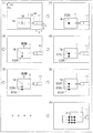
撮像部40は、ロボット10のハンド部13に保持されたワーク1を撮像するように構成されている。また、撮像部40は、ロボット10の上方に固定的に設置されている。また、撮像部40に撮像された画像は、たとえば、図2に示すように、画像上の座標として、左上を基準にしてXvおよびYvの座標を有している。
The
ここで、本実施形態では、ビジョンコントローラ30は、ロボットコントローラ20にワーク1を移動させるための移動情報を送信して、ロボット10に保持されたワーク1を移動させて撮像部40によりワーク1を複数の位置において撮像し、ロボット10に保持されたワーク1の登録された部分1bを複数の位置において認識して、認識結果と移動情報とに基づいて、撮像部40により撮像される画像の位置情報と、ロボット10の位置情報とを対応づけるキャリブレーションを行うように構成されている。
Here, in this embodiment, the
具体的には、ビジョンコントローラ30は、図2および図3に示すように、ロボット10に保持されたワーク1の登録された部分1bの領域内で特徴部分1aを抽出するとともに、ワーク1の特徴部分1aを複数の位置において撮像部40により撮像し、ワーク1の特徴部分1aの移動状態を取得し、ワーク1の特徴部分1aの移動状態と、移動情報とに基づいて、キャリブレーションを行うように構成されている。なお、ワーク1の部分1bは、ワーク1の種類毎に予めユーザにより登録されている。たとえば、ワーク1の主要部分や特徴的な形状・模様を有する部分が登録される。また、バリなどの不確定な部分(ワーク毎に形状が異なる部分)ではないワーク1の部分が登録される。また、ビジョンコントローラ30は、ワーク1の登録された部分1bから1つ以上の特徴部分1aを抽出して、ワーク1の位置および姿勢を認識するために抽出した特徴部分1aを用いるように構成されている。
Specifically, as shown in FIGS. 2 and 3, the
また、ビジョンコントローラ30は、ロボットコントローラ20に移動量情報を含む移動情報を送信して、ロボット10に保持されたワーク1を複数回平行移動させて撮像部40によりワーク1を複数の位置において撮像し、移動量情報と、撮像部40により複数回撮像されたワーク1の撮像結果とに基づいて、撮像部40により撮像される画像の座標情報と、ロボット10の座標情報とを対応づけるように構成されている。
In addition, the
具体的には、図2に示すように、ビジョンコントローラ30は、ロボットコントローラ20に移動量情報を含む移動情報を送信して、ロボット10に保持されたワーク1を水平面内の第1の方向(X方向)に複数回移動させるとともに、第1の方向と直交する水平面内の第2の方向(Y方向)に複数回移動させることにより、ワーク1を格子状に平行移動させて撮像部40によりワーク1を複数の位置において撮像する。また、ビジョンコントローラ30は、移動情報と、撮像部40により複数回撮像されたワーク1の撮像結果とに基づいて、撮像部40により撮像される画像の座標情報と、ロボット10の座標情報とを対応づけるように構成されている。
Specifically, as shown in FIG. 2, the
図2の(1)に示すように、撮像部40の撮像範囲(画角内)にワーク1が移動されて、ロボット10に保持されたワーク1が撮像される。次に、図2の(2)に示すように、画像内のワーク1の特徴部分1aが認識される。そして、認識された特徴部分1aに対応する画像上にマーク2(2a)が記される。図2の(3)に示すように、ビジョンコントローラ30から送信される移動情報に基づいてワーク1がY方向に平行移動される。図2の(4)に示すように、画像内の移動後のワーク1の特徴部分1aが認識される。そして、認識された移動後の特徴部分1aに対応する画像上にマーク2(2b)が記される。
As shown in (1) of FIG. 2, the
そして、図2の(5)に示すように、ビジョンコントローラ30から送信される移動情報に基づいてワーク1がさらにY方向に平行移動される。図2の(6)に示すように、画像内の移動後のワーク1の特徴部分1aが認識される。そして、認識された移動後の特徴部分1aに対応する画像上にマーク2(2c)が記される。その後、ワーク1がX方向およびY方向に複数回移動して、撮像および認識によりマーク2が複数記される。その結果、図2の(A)に示すように、マーク2が格子状に記録される。この記された複数のマーク2の座標位置と、ワーク1を移動させた移動情報とに基づいて、撮像部40により撮像される画像の座標情報と、ロボット10の座標情報とが対応づけられるキャリブレーションが行われる。
Then, as shown in (5) of FIG. 2, the
また、図3に示すように、ビジョンコントローラ30は、ロボットコントローラ20に回動情報を含む移動情報を送信して、ロボット10に保持されたワーク1を平行移動とは別に複数回回動させて撮像部40によりワーク1を複数の回動位置において撮像し、回動情報と、撮像部40により複数回撮像されたワーク1の撮像結果とに基づいて、撮像部40により撮像される画像における画像内回動中心と、ロボット10によりワーク1を回動させる回動中心とを対応づけるように構成されている。
As shown in FIG. 3, the
図3の(11)に示すように、撮像部40の撮像範囲(画角内)にワーク1が移動されて、ロボット10に保持されたワーク1が撮像される。次に、図3の(12)に示すように、画像内のワーク1の特徴部分1aが認識される。そして、認識された特徴部分1aに対応する画像上にマーク3(3a)が記される。図3の(13)に示すように、ビジョンコントローラ30から送信される回動情報を含む移動情報に基づいてワーク1が制御点14を中心に時計回りに角度θ回動される。図3の(14)に示すように、画像内の移動後のワーク1の特徴部分1aが認識される。そして、認識された移動後の特徴部分1aに対応する画像上にマーク3(3b)が記される。
As shown in (11) of FIG. 3, the
そして、図3の(15)に示すように、ビジョンコントローラ30から送信される回動情報に基づいてワーク1がさらに制御点14を中心に時計回りに角度θ回動される。図3の(16)に示すように、画像内の移動後のワーク1の特徴部分1aが認識される。そして、認識された移動後の特徴部分1aに対応する画像上にマーク3(3c)が記される。その後、ワーク1が複数回回動されて、図3の(B)に示すように、撮像および認識によりマーク3が複数記される。この記された複数のマーク3の座標位置と、ワーク1を回動させた回動情報とに基づいて、撮像部40により撮像される画像における画像内回動中心と、ロボット10によりワーク1を回動させる回動中心とが対応づけられるキャリブレーションが行われる。
Then, as shown in FIG. 3 (15), the
また、ビジョンコントローラ30は、ロボットコントローラ20に回動情報を含む移動情報を送信して、ロボット10に保持されたワーク1を回動させて撮像部40によりワーク1を複数の回動位置において撮像し、撮像部40により複数回撮像されたワーク1の撮像結果に基づいて、撮像部40により撮像される画像における画像内回動中心を算出する動作を繰り返し行い、画像内回動中心と、移動情報とに基づいて、撮像部40により撮像される画像の位置情報と、ロボット10の位置情報とを対応づけるように構成されている。
In addition, the
また、ビジョンコントローラ30は、キャリブレーション時に登録されたワーク1の部分1bを用いて、ロボット10に保持された作業対象のワーク1の位置および姿勢を認識して、キャリブレーション結果に基づいて作業対象のワーク1の位置を補正するように構成されている。具体的には、キャリブレーション時に用いたワーク1と同じ種類のワーク1が作業対象の場合、ビジョンコントローラ30は、作業対象のワーク1を認識するための登録を再度行うことなく、キャリブレーション時に登録されたワーク1の部分1bを用いてワーク1を認識するように構成されている。
Further, the
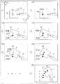
次に、図4および図5を参照して、本実施形態によるロボットシステム100のワーク認識処理について説明する。
Next, with reference to FIG. 4 and FIG. 5, the workpiece recognition process of the
図4のステップS1において、ロボットコントローラ20とビジョンコントローラ30とが接続される。ステップS2において、ビジョンコントローラ30の設定が行われる。具体的には、ロボットコントローラ20とビジョンコントローラ30との間で通信が可能となるように、ビジョンコントローラ30が設定される。ステップS3において、ビジョン条件ファイルが設定される。具体的には、ワーク1の位置および姿勢が認識される際のビジョン条件(キャリブレーション結果)を保存するファイルが指定される。なお、ビジョン条件は、ロボットコントローラ20側に保存される。
In step S1 of FIG. 4, the
ステップS4において、ロボットコントローラ20にパラメータおよび変数の定義が行われる。つまり、ロボット10を駆動させるための駆動情報を含むパラメータおよび変数が定義される。ステップS5において、ロボットコントローラ20に対して検出ジョブの作成および実行が行われる。これにより、ロボットコントローラ20とビジョンコントローラ30との間で通信が行われ、ビジョンコントローラ30による画像処理の結果に応じてロボット10を制御することが可能となる。
In step S4, parameters and variables are defined in the
ステップS6において、キャリブレーション処理が実行される。これにより、撮像部40により撮像される画像の位置情報と、ロボット10の位置情報とが対応づけられる。ステップS7において、計測用基準ワーク登録が行われる。具体的には、ワーク1に作業を行う際に、ワーク1が位置する基準となる位置が登録される。ステップS8において、作業対象のワーク1が計測(撮像および認識)される。そして、ステップS9において、作業対象のワーク1が基準ワーク登録された位置に位置するように補正(移動)される。
In step S6, calibration processing is executed. Thereby, the positional information of the image captured by the
その後、基準ワーク登録されたワーク1を続けて作業する場合は、ステップS8およびステップS9の処理が繰り返される。また、基準ワーク登録されていないワーク1を作業する場合は、ステップS7の計測用基準ワーク登録処理に戻る。また、ロボット10と、撮像部40との位置関係が変更された場合は、ステップS6のキャリブレーション処理に戻る。そして、所定の数のワーク1の作業が終了後、ワーク認識処理が終了される。
After that, when the
次に、図5を参照して、図4のステップS6のキャリブレーション処理について詳細に説明する。 Next, with reference to FIG. 5, the calibration process in step S6 of FIG. 4 will be described in detail.
図5のステップS11において、キャリブレーション用ワークの登録が行われる。具体的には、キャリブレーションに用いるワーク1の認識させるための部分1b(図2および図3参照)がビジョンコントローラ30側で登録される。ステップS12において、キャリブレーションを行うためにロボットコントローラ20側でキャリブレーションジョブが作成される。具体的には、ロボットコントローラ20において、ビジョンコントローラ30の移動情報に基づいて、ロボット10を駆動させるようにジョブが作成される。
In step S11 of FIG. 5, calibration work registration is performed. Specifically, a
ステップS13において、シフトデータ(X,Y)(移動情報)がビジョンコントローラ30から送信され、ロボットコントローラ20で受信される。ステップS14において、シフトデータ(X,Y)(移動情報)に基づいて、ロボットコントローラ20により、ロボット本体11が駆動されてワーク1がXY方向に水平移動される。ステップS15において、ワーク1が撮像部40により撮像される。
In step S <b> 13, shift data (X, Y) (movement information) is transmitted from the
ステップS16において、ワーク1が検出(ワーク1の特徴部分1aが認識)されたか否かが判断される。ワーク1が検出されれば、ステップS17に進み、ワーク1が検出されなければ、ステップS23に進む。ステップS17において、継続して判定(撮像および認識)を行うか否かが判断される。つまり、所定の回数だけ判定(撮像および認識)が行われたか否かが判断される。継続して判定するならば、ステップS13に戻り、判定が終了すれば、ステップS18に進む。これにより、ビジョンコントローラ30により、撮像部40により撮像された画像の方向および移動量(尺度)と、ロボット10の移動方向および移動量とが対応づけられる。
In step S16, it is determined whether or not the
ステップS18において、シフトデータ(θ)(移動情報)がビジョンコントローラ30から送信され、ロボットコントローラ20で受信される。ステップS19において、シフトデータ(θ)(移動情報)に基づいて、ロボットコントローラ20により、ロボット本体11が駆動されてワーク1が角度θ回動される。ステップS20において、ワーク1が撮像部40により撮像される。
In step S <b> 18, the shift data (θ) (movement information) is transmitted from the
ステップS21において、ワーク1が検出(ワーク1の特徴部分1aが認識)されたか否かが判断される。ワーク1が検出されれば、ステップS22に進み、ワーク1が検出されなければ、ステップS23に進む。ステップS22において、継続して判定(撮像および認識)を行うか否かが判断される。つまり、所定の回数だけ判定(撮像および認識)が行われたか否かが判断される。また、ワーク1を撮像して算出した画像内回動中心が一定の範囲内に収束するように撮像および算出を繰り返すか否かが判断される。継続して判定するならば、ステップS18に戻り、判定が終了すれば、キャリブレーション結果を登録してキャリブレーション処理を終了する。これにより、ビジョンコントローラ30により、撮像部40により撮像された画像の画像内回動中心と、ロボット10のワーク1を回動させる回動中心とが対応づけられる。
In step S21, it is determined whether or not the
ステップS16またはステップS21においてワーク1が検出されなければ、ステップS23において、エラーが通知されてキャリブレーション処理が中止される。
If the
本実施形態では、以下のような効果を得ることができる。 In the present embodiment, the following effects can be obtained.
本実施形態では、上記のように、ビジョンコントローラ30を、ロボットコントローラ20にワーク1を移動させるための移動情報を送信して、ロボット10に保持されたワーク1を移動させて撮像部40によりワーク1を複数の位置において撮像し、ロボット10に保持されたワーク1の登録された部分1bを複数の位置において認識して、認識結果と移動情報とに基づいて、撮像部40により撮像される画像の位置情報と、ロボット10の位置情報とを対応づけるキャリブレーションを行うように構成する。これにより、キャリブレーション用のチェッカーボードを用いることなく、作業対象のワーク1を用いて撮像部40により撮像される画像の位置情報とロボット10の位置情報とを対応づけるキャリブレーションを行うことができるので、部品点数の増加を抑制しつつ、撮像部40により撮像される画像の位置情報と、ロボット10の位置情報とを対応づけるキャリブレーションを行うことができる。また、キャリブレーションの際にビジョンコントローラ30から送信される移動情報に基づいて、ロボット10が駆動されるので、ロボットコントローラ20側においてロボット10の移動状態を記録しなくても、ビジョンコントローラ30側でキャリブレーションの処理を行うことができる。これにより、キャリブレーションの処理が複雑化するのを抑制することができる。
In the present embodiment, as described above, the
また、本実施形態では、上記のように、ビジョンコントローラ30を、キャリブレーション時に登録されたワーク1の部分1bを用いて、ロボット10に保持された作業対象のワーク1の位置および姿勢を認識して、キャリブレーション結果に基づいて作業対象のワーク1の位置を補正するように構成する。これにより、キャリブレーション時に登録されたワーク1と同じ種類のワーク1に作業を行う場合には、作業対象のワーク1を認識するためにワーク1の部分を再度登録する必要がないので、その分、ワーク1の位置および姿勢を認識するための作業負担および処理負担を軽減することができる。
In the present embodiment, as described above, the
また、本実施形態では、上記のように、ビジョンコントローラ30を、ロボット10に保持されたワーク1の登録された部分1bの領域内で特徴部分1aを抽出するとともに、ワーク1の特徴部分1aを複数の移動された位置において撮像部40により撮像し、ワーク1の特徴部分1aの移動状態を取得し、ワーク1の特徴部分1aの移動状態と、移動情報とに基づいて、キャリブレーションを行うように構成する。これにより、ワーク1の登録された部分1bからビジョンコントローラ30により認識しやすい特徴部分1aを自動的に抽出してキャリブレーションに用いることができるので、より精度よくキャリブレーションを行うことができる。
Further, in the present embodiment, as described above, the
また、本実施形態では、上記のように、ビジョンコントローラ30を、ロボットコントローラ20に移動量情報を含む移動情報を送信して、ロボット10に保持されたワーク1を複数回平行移動させて撮像部40によりワーク1を複数の位置において撮像し、移動量情報と、撮像部40により複数回撮像されたワーク1の撮像結果とに基づいて、撮像部40により撮像される画像の座標情報と、ロボット10の座標情報とを対応づけるように構成する。これにより、移動量情報に基づくワーク1の実際の移動と、撮像部40により撮像された画像上のワーク1の移動とに基づいて、撮像部40により撮像される画像の座標情報と、ロボット10の座標情報とを容易に対応づけることができる。
Further, in the present embodiment, as described above, the
また、本実施形態では、上記のように、ビジョンコントローラ30を、ロボットコントローラ20に移動情報を送信して、ロボット10に保持されたワーク1を水平面内の第1の方向(X方向)に複数回移動させるとともに、第1の方向と直交する水平面内の第2の方向(Y方向)に複数回移動させることにより、ワーク1を格子状に平行移動させて撮像部40によりワーク1を複数の位置において撮像し、移動情報と、撮像部40により複数回撮像されたワーク1の撮像結果とに基づいて、撮像部40により撮像される画像の座標情報と、ロボット10の座標情報とを対応づけるように構成する。これにより、水平面内を2次元的にワーク1を移動させて格子状の複数の位置においてワーク1を撮像した撮像結果と、移動情報に基づくワーク1の実際の移動とに基づいてキャリブレーションが行われるので、直線的に(1次元的に)移動させる場合に比べて、キャリブレーションをより精度よく行うことができる。
In the present embodiment, as described above, the
また、本実施形態では、上記のように、ビジョンコントローラ30を、ロボットコントローラ20に回動情報を含む移動情報を送信して、ロボット10に保持されたワーク1を平行移動とは別に複数回回動させて撮像部40によりワーク1を複数の回動位置において撮像し、回動情報と、撮像部40により複数回撮像されたワーク1の撮像結果とに基づいて、撮像部40により撮像される画像における画像内回動中心と、ロボット10によりワーク1を回動させる回動中心とを対応づけるように構成する。これにより、回動情報に基づくワーク1の実際の移動(回動)と、撮像部40により撮像された画像上のワーク1の移動(回動)とに基づいて、撮像部40により撮像される画像の画像内回動中心と、ロボット10によりワーク1を回動させる回動中心とを容易に対応づけることができる。
In the present embodiment, as described above, the
また、本実施形態では、上記のように、ビジョンコントローラ30を、ロボットコントローラ20に移動情報を送信して、ロボット10に保持されたワーク1を回動させて撮像部40によりワーク1を複数の回動位置において撮像し、撮像部40により複数回撮像されたワーク1の撮像結果に基づいて、撮像部40により撮像される画像における画像内回動中心を算出する動作を繰り返し行い、画像内回動中心と、移動情報とに基づいて、撮像部40により撮像される画像の位置情報と、ロボット10の位置情報とを対応づけるように構成されている。これにより、複数の回動位置においてワーク1を撮像して求めた画像内回動中心が一定の範囲内に収束するまで撮像および算出を繰り返すことによって、画像内回動中心を精度よく算出することができるので、撮像部40により撮像される画像の画像内回動中心と、ロボット10によりワーク1を回動させる回動中心とをより精度よく対応づけることができる。
Further, in the present embodiment, as described above, the
なお、今回開示された実施形態は、すべての点で例示であって制限的なものではないと考えられるべきである。本発明の範囲は、上記した実施形態の説明ではなく特許請求の範囲によって示され、さらに特許請求の範囲と均等の意味および範囲内でのすべての変更が含まれる。 The embodiment disclosed this time should be considered as illustrative in all points and not restrictive. The scope of the present invention is shown not by the above description of the embodiments but by the scope of claims for patent, and further includes all modifications within the meaning and scope equivalent to the scope of claims for patent.
たとえば、上記実施形態では、撮像部により平面的(2次元的)な位置を認識する構成の例を示したが、撮像部が3次元カメラを含み、撮像部により3次元的な位置を認識する構成であってもよい。 For example, in the above-described embodiment, an example of a configuration in which a planar (two-dimensional) position is recognized by the imaging unit has been described. However, the imaging unit includes a three-dimensional camera, and the imaging unit recognizes a three-dimensional position. It may be a configuration.
また、上記実施形態では、水平面内を格子状にワークを移動させてキャリブレーションを行う構成を示したが、3次元的に格子状(直方体格子状)にワークを移動させてキャリブレーションを行ってもよい。 In the above embodiment, the calibration is performed by moving the workpiece in a grid pattern in the horizontal plane. However, the calibration is performed by moving the workpiece in a three-dimensional grid pattern (cubic grid pattern). Also good.
また、上記実施形態では、ビジョンコントローラ(撮像部制御手段)と、ロボットコントローラ(ロボット制御手段)とが別個に設けられている構成の例を示したが、撮像制御手段とロボット制御手段とが一体のコントローラに設けられていてもよい。 In the above embodiment, the vision controller (imaging unit control means) and the robot controller (robot control means) are separately provided. However, the imaging control means and the robot control means are integrated. It may be provided in the controller.
また、上記実施形態では、撮像部が固定的に設置されている例を示したが、撮像部が移動可能に構成されていてもよい。この場合、撮像部の移動毎にキャリブレーションを行ってもよいし、撮像部の移動状態からキャリブレーションの補正を行ってもよい。 In the above embodiment, an example in which the imaging unit is fixedly installed has been described. However, the imaging unit may be configured to be movable. In this case, calibration may be performed every time the imaging unit moves, or calibration may be corrected based on the movement state of the imaging unit.
また、上記実施形態では、説明の便宜上、制御手段による制御処理を処理フローに沿って順番に処理を行うフロー駆動型のフローチャートを用いて説明したが、本発明はこれに限られない。本発明では、制御手段による処理を、イベント単位で処理を実行するイベント駆動型(イベントドリブン型)の処理により行ってもよい。この場合、完全なイベント駆動型で行ってもよいし、イベント駆動およびフロー駆動を組み合わせて行ってもよい。 In the above embodiment, for convenience of explanation, the control processing by the control means has been described using a flow-driven flowchart in which processing is performed in order along the processing flow. However, the present invention is not limited to this. In the present invention, the processing by the control means may be performed by event driven type (event driven type) processing that executes processing in units of events. In this case, it may be performed by a complete event drive type or a combination of event drive and flow drive.
1 ワーク
10 ロボット
11 ロボット本体
13 ハンド部
20 ロボットコントローラ(ロボット制御手段)
30 ビジョンコントローラ(撮像制御手段)
40 撮像部
100 ロボットシステム
DESCRIPTION OF
30 Vision controller (imaging control means)
40
Claims (9)
前記ロボットの前記ハンド部に保持された前記ワークを撮像する撮像部と、
前記撮像部の撮像動作を制御する撮像制御手段と、
前記ロボット本体の駆動を制御するロボット制御手段と、を備え、
前記撮像制御手段は、前記ロボット制御手段に前記ワークを移動させるための移動情報を送信して、前記ロボットに保持された前記ワークを移動させて前記撮像部により前記ワークを複数の位置において撮像し、前記ロボットに保持された前記ワークの登録された部分を複数の位置において認識して、認識結果と前記移動情報とに基づいて、前記撮像部により撮像される画像の位置情報と、前記ロボットの位置情報とを対応づけるキャリブレーションを行うように構成されている、ロボットシステム。 A robot including a hand unit for holding a workpiece and an articulated robot body to which the hand unit is attached;
An imaging unit for imaging the workpiece held by the hand unit of the robot;
Imaging control means for controlling the imaging operation of the imaging unit;
Robot control means for controlling the drive of the robot body,
The imaging control unit transmits movement information for moving the workpiece to the robot control unit, moves the workpiece held by the robot, and images the workpiece at a plurality of positions by the imaging unit. , Recognizing a registered part of the workpiece held by the robot at a plurality of positions, and based on a recognition result and the movement information, positional information of an image captured by the imaging unit, A robot system configured to perform calibration for associating position information.
撮像制御手段により送信される移動情報に基づいて前記ロボットに保持された前記ワークを移動させて撮像部により前記ワークを複数の位置において撮像する工程と、
撮像結果に基づいて前記ロボットに保持された前記ワークの登録された部分を複数の位置において認識する工程と、
認識結果と前記移動情報とに基づいて、前記撮像部により撮像される画像の位置情報と、前記ロボットの位置情報とを対応づけてキャリブレーションを完了させる工程とを備える、ロボットシステムのキャリブレーション方法。 A process of holding a workpiece by a hand unit attached to an articulated robot body;
Moving the workpiece held by the robot based on movement information transmitted by the imaging control means, and imaging the workpiece at a plurality of positions by an imaging unit;
Recognizing a registered portion of the work held by the robot at a plurality of positions based on an imaging result;
A calibration method for a robot system, comprising: a step of associating position information of an image captured by the image capturing unit with position information of the robot based on a recognition result and the movement information, and completing calibration. .
撮像制御手段により送信される移動情報に基づいて前記ロボットに保持された前記ワークを移動させて撮像部により前記ワークを複数の位置において撮像する工程と、
撮像結果に基づいて前記ロボットに保持された前記ワークの登録された部分を複数の位置において認識する工程と、
認識結果と前記移動情報とに基づいて、前記撮像部により撮像される画像の位置情報と、前記ロボットの位置情報とを対応づけるキャリブレーション工程と、
前記ロボットに保持された作業対象の前記ワークの位置および姿勢を認識して、キャリブレーション結果に基づいて作業対象の前記ワークの位置を補正する工程とを備える、ロボットシステムの位置補正方法。 A process of holding a workpiece by a hand unit attached to an articulated robot body;
Moving the workpiece held by the robot based on movement information transmitted by the imaging control means, and imaging the workpiece at a plurality of positions by an imaging unit;
Recognizing a registered portion of the work held by the robot at a plurality of positions based on an imaging result;
A calibration step of associating position information of an image captured by the image capturing unit with position information of the robot based on a recognition result and the movement information;
Recognizing the position and posture of the work as a work target held by the robot, and correcting the position of the work as a work target based on a calibration result.
Priority Applications (4)
| Application Number | Priority Date | Filing Date | Title |
|---|---|---|---|
| JP2014053072A JP2015174191A (en) | 2014-03-17 | 2014-03-17 | Robot system, calibration method of robot system and position correction method of robot system |
| EP15150748.0A EP2921267A3 (en) | 2014-03-17 | 2015-01-12 | Robot system, calibration method in robot system, and position correcting method in robot system |
| CN201510028932.1A CN104924309A (en) | 2014-03-17 | 2015-01-20 | Robot system, calibration method in robot system, and position correcting method in robot system |
| US14/604,060 US20150258688A1 (en) | 2014-03-17 | 2015-01-23 | Robot system, calibration method in robot system, and position correcting method in robot system |
Applications Claiming Priority (1)
| Application Number | Priority Date | Filing Date | Title |
|---|---|---|---|
| JP2014053072A JP2015174191A (en) | 2014-03-17 | 2014-03-17 | Robot system, calibration method of robot system and position correction method of robot system |
Publications (1)
| Publication Number | Publication Date |
|---|---|
| JP2015174191A true JP2015174191A (en) | 2015-10-05 |
Family
ID=52345076
Family Applications (1)
| Application Number | Title | Priority Date | Filing Date |
|---|---|---|---|
| JP2014053072A Pending JP2015174191A (en) | 2014-03-17 | 2014-03-17 | Robot system, calibration method of robot system and position correction method of robot system |
Country Status (4)
| Country | Link |
|---|---|
| US (1) | US20150258688A1 (en) |
| EP (1) | EP2921267A3 (en) |
| JP (1) | JP2015174191A (en) |
| CN (1) | CN104924309A (en) |
Cited By (7)
| Publication number | Priority date | Publication date | Assignee | Title |
|---|---|---|---|---|
| DE102018200154A1 (en) | 2017-01-12 | 2018-07-12 | Fanuc Corporation | Calibration device, calibration method and program for a visual sensor |
| JP2018111165A (en) * | 2017-01-12 | 2018-07-19 | ファナック株式会社 | Calibration device of visual sensor, method and program |
| KR101927132B1 (en) * | 2017-03-20 | 2018-12-11 | 전자부품연구원 | Learning-based Logistics Automation System, Device and Method |
| JP2019025578A (en) * | 2017-07-28 | 2019-02-21 | セイコーエプソン株式会社 | Control device, robot system, and control method |
| JP2019119005A (en) * | 2018-01-05 | 2019-07-22 | 株式会社Fdkエンジニアリング | Calibration method of component assembly device |
| JP2020006502A (en) * | 2018-07-10 | 2020-01-16 | 株式会社星宇ハイテックSungwoo Hitech Co., Ltd. | Robot system for assembling component and control method |
| US10628966B1 (en) | 2019-03-07 | 2020-04-21 | Mujin, Inc. | Method and system for performing automatic camera calibration for robot control |
Families Citing this family (13)
| Publication number | Priority date | Publication date | Assignee | Title |
|---|---|---|---|---|
| US10179407B2 (en) * | 2014-11-16 | 2019-01-15 | Robologics Ltd. | Dynamic multi-sensor and multi-robot interface system |
| CN105182907A (en) * | 2015-10-20 | 2015-12-23 | 上海拓璞数控科技有限公司 | Robot gesture on-line correction system and correction method thereof |
| CN105773661B (en) * | 2016-03-30 | 2018-08-21 | 广东速美达自动化股份有限公司 | Workpiece translational motion rotates scaling method under horizontal machine people's fixed camera |
| JP6854610B2 (en) * | 2016-09-16 | 2021-04-07 | Juki株式会社 | Sewing system |
| CN109789548B (en) | 2016-11-08 | 2022-06-28 | Abb瑞士股份有限公司 | Method for workpiece calibration and robot system using the same |
| DE102016223841A1 (en) * | 2016-11-30 | 2018-05-30 | Siemens Healthcare Gmbh | Calculate a calibration parameter of a robot tool |
| JP7035727B2 (en) * | 2018-03-30 | 2022-03-15 | 日本電産株式会社 | Calibration accuracy evaluation method and evaluation device |
| CN109309791B (en) * | 2018-11-09 | 2021-01-29 | 珠海格力智能装备有限公司 | Method and system for controlling camera to take pictures |
| US11918297B2 (en) * | 2019-01-10 | 2024-03-05 | Mazor Robotics Ltd. | System and method for registration between coordinate systems and navigation |
| US11135025B2 (en) | 2019-01-10 | 2021-10-05 | Medtronic Navigation, Inc. | System and method for registration between coordinate systems and navigation |
| US10399227B1 (en) * | 2019-03-29 | 2019-09-03 | Mujin, Inc. | Method and control system for verifying and updating camera calibration for robot control |
| US10906184B2 (en) | 2019-03-29 | 2021-02-02 | Mujin, Inc. | Method and control system for verifying and updating camera calibration for robot control |
| CN110275532B (en) * | 2019-06-21 | 2020-12-15 | 珠海格力智能装备有限公司 | Robot control method and device and visual equipment control method and device |
Citations (9)
| Publication number | Priority date | Publication date | Assignee | Title |
|---|---|---|---|---|
| JPS6257892A (en) * | 1985-09-04 | 1987-03-13 | 松下電器産業株式会社 | Camera coordinate calibrating method of robot with visual sense |
| JPH10340112A (en) * | 1997-06-06 | 1998-12-22 | Matsushita Electric Ind Co Ltd | Robot with automatic calibration function |
| JPH1185235A (en) * | 1997-09-01 | 1999-03-30 | Yaskawa Electric Corp | Visual feedback method for machine device using image pickup unit |
| JP2002307346A (en) * | 2001-04-18 | 2002-10-23 | Mitsubishi Electric Corp | Method and device for calibrating visual coordinates of robot |
| JP2003305675A (en) * | 2002-04-15 | 2003-10-28 | Denso Wave Inc | Visual recognition device |
| JP2006082170A (en) * | 2004-09-15 | 2006-03-30 | Fuji Photo Film Co Ltd | Calibration method |
| US20090076655A1 (en) * | 2007-09-14 | 2009-03-19 | Zimmer, Inc. | Robotic calibration method |
| JP2009248214A (en) * | 2008-04-03 | 2009-10-29 | Kanto Auto Works Ltd | Image processing device and robot control system |
| WO2014037993A1 (en) * | 2012-09-04 | 2014-03-13 | 富士機械製造株式会社 | Work device |
Family Cites Families (15)
| Publication number | Priority date | Publication date | Assignee | Title |
|---|---|---|---|---|
| JP3002097B2 (en) * | 1994-08-25 | 2000-01-24 | ファナック株式会社 | Visual tracking method |
| US6044308A (en) * | 1997-06-13 | 2000-03-28 | Huissoon; Jan Paul | Method and device for robot tool frame calibration |
| US6304050B1 (en) * | 1999-07-19 | 2001-10-16 | Steven B. Skaar | Means and method of robot control relative to an arbitrary surface using camera-space manipulation |
| US6681151B1 (en) * | 2000-12-15 | 2004-01-20 | Cognex Technology And Investment Corporation | System and method for servoing robots based upon workpieces with fiducial marks using machine vision |
| US6466841B2 (en) * | 2001-02-14 | 2002-10-15 | Xerox Corporation | Apparatus and method for determining a reference position for an industrial robot |
| JP2010152550A (en) * | 2008-12-24 | 2010-07-08 | Canon Inc | Work apparatus and method for calibrating the same |
| JP5365218B2 (en) | 2009-01-28 | 2013-12-11 | 富士電機株式会社 | Robot vision system and automatic calibration method |
| DE102009014766B4 (en) * | 2009-03-25 | 2012-02-09 | Fraunhofer-Gesellschaft zur Förderung der angewandten Forschung e.V. | Superimposed axes in a device for machining a workpiece with a tool |
| EP2255930A1 (en) * | 2009-05-27 | 2010-12-01 | Leica Geosystems AG | Method and system for extremely precise positioning of at least one object in the end position in space |
| JP4763074B2 (en) * | 2009-08-03 | 2011-08-31 | ファナック株式会社 | Measuring device and measuring method of position of tool tip of robot |
| TWI404609B (en) * | 2010-10-21 | 2013-08-11 | Ind Tech Res Inst | Parameters adjustment method of robotic arm system and adjustment apparatus |
| JP5928114B2 (en) * | 2012-04-12 | 2016-06-01 | セイコーエプソン株式会社 | Robot system, robot system calibration method, robot |
| JP6025386B2 (en) * | 2012-05-02 | 2016-11-16 | キヤノン株式会社 | Image measuring apparatus, image measuring method, and image measuring program |
| CN102922521B (en) * | 2012-08-07 | 2015-09-09 | 中国科学技术大学 | A kind of mechanical arm system based on stereoscopic vision servo and real-time calibration method thereof |
| JP2014180720A (en) * | 2013-03-19 | 2014-09-29 | Yaskawa Electric Corp | Robot system and calibration method |
-
2014
- 2014-03-17 JP JP2014053072A patent/JP2015174191A/en active Pending
-
2015
- 2015-01-12 EP EP15150748.0A patent/EP2921267A3/en not_active Withdrawn
- 2015-01-20 CN CN201510028932.1A patent/CN104924309A/en active Pending
- 2015-01-23 US US14/604,060 patent/US20150258688A1/en not_active Abandoned
Patent Citations (9)
| Publication number | Priority date | Publication date | Assignee | Title |
|---|---|---|---|---|
| JPS6257892A (en) * | 1985-09-04 | 1987-03-13 | 松下電器産業株式会社 | Camera coordinate calibrating method of robot with visual sense |
| JPH10340112A (en) * | 1997-06-06 | 1998-12-22 | Matsushita Electric Ind Co Ltd | Robot with automatic calibration function |
| JPH1185235A (en) * | 1997-09-01 | 1999-03-30 | Yaskawa Electric Corp | Visual feedback method for machine device using image pickup unit |
| JP2002307346A (en) * | 2001-04-18 | 2002-10-23 | Mitsubishi Electric Corp | Method and device for calibrating visual coordinates of robot |
| JP2003305675A (en) * | 2002-04-15 | 2003-10-28 | Denso Wave Inc | Visual recognition device |
| JP2006082170A (en) * | 2004-09-15 | 2006-03-30 | Fuji Photo Film Co Ltd | Calibration method |
| US20090076655A1 (en) * | 2007-09-14 | 2009-03-19 | Zimmer, Inc. | Robotic calibration method |
| JP2009248214A (en) * | 2008-04-03 | 2009-10-29 | Kanto Auto Works Ltd | Image processing device and robot control system |
| WO2014037993A1 (en) * | 2012-09-04 | 2014-03-13 | 富士機械製造株式会社 | Work device |
Cited By (13)
| Publication number | Priority date | Publication date | Assignee | Title |
|---|---|---|---|---|
| US10647001B2 (en) | 2017-01-12 | 2020-05-12 | Fanuc Corporation | Calibration device, calibration method, and computer readable medium for visual sensor |
| JP2018111165A (en) * | 2017-01-12 | 2018-07-19 | ファナック株式会社 | Calibration device of visual sensor, method and program |
| DE102018200154A1 (en) | 2017-01-12 | 2018-07-12 | Fanuc Corporation | Calibration device, calibration method and program for a visual sensor |
| DE102018200155B4 (en) | 2017-01-12 | 2020-08-06 | Fanuc Corporation | Calibration device, calibration method and program for a visual sensor |
| US10434654B2 (en) | 2017-01-12 | 2019-10-08 | Fanuc Corporation | Calibration device, calibration method, and computer readable medium for visual sensor |
| KR101927132B1 (en) * | 2017-03-20 | 2018-12-11 | 전자부품연구원 | Learning-based Logistics Automation System, Device and Method |
| JP2019025578A (en) * | 2017-07-28 | 2019-02-21 | セイコーエプソン株式会社 | Control device, robot system, and control method |
| JP2019119005A (en) * | 2018-01-05 | 2019-07-22 | 株式会社Fdkエンジニアリング | Calibration method of component assembly device |
| JP7064884B2 (en) | 2018-01-05 | 2022-05-11 | 株式会社Fdkエンジニアリング | Calibration method of parts assembly device |
| JP2020006502A (en) * | 2018-07-10 | 2020-01-16 | 株式会社星宇ハイテックSungwoo Hitech Co., Ltd. | Robot system for assembling component and control method |
| US10628966B1 (en) | 2019-03-07 | 2020-04-21 | Mujin, Inc. | Method and system for performing automatic camera calibration for robot control |
| US10636172B1 (en) | 2019-03-07 | 2020-04-28 | Mujin, Inc. | Method and system for performing automatic camera calibration for robot control |
| JP2020144829A (en) * | 2019-03-07 | 2020-09-10 | 株式会社Mujin | Method and system for performing automatic camera calibration for robot control |
Also Published As
| Publication number | Publication date |
|---|---|
| EP2921267A3 (en) | 2016-06-29 |
| EP2921267A2 (en) | 2015-09-23 |
| US20150258688A1 (en) | 2015-09-17 |
| CN104924309A (en) | 2015-09-23 |
Similar Documents
| Publication | Publication Date | Title |
|---|---|---|
| JP2015174191A (en) | Robot system, calibration method of robot system and position correction method of robot system | |
| JP6770605B2 (en) | Vision system for training the assembly system by virtual assembly of the object | |
| US9884425B2 (en) | Robot, robot control device, and robotic system | |
| JP5815761B2 (en) | Visual sensor data creation system and detection simulation system | |
| CN106426161B (en) | System and method for correlating machine vision coordinate spaces in a guided assembly environment | |
| JP2022028672A (en) | System and method for automatic hand-eye calibration of vision system for robot motion | |
| US20200198145A1 (en) | Method and apparatus of non-contact tool center point calibration for a mechanical arm, and a mechanical arm system with said calibration function | |
| TWI670153B (en) | Robot and robot system | |
| JP6429473B2 (en) | Robot system, robot system calibration method, program, and computer-readable recording medium | |
| JP6812095B2 (en) | Control methods, programs, recording media, robotic devices, and manufacturing methods for articles | |
| WO2021012122A1 (en) | Robot hand-eye calibration method and apparatus, computing device, medium and product | |
| US20100119146A1 (en) | Robot system, robot control device and method for controlling robot | |
| JP6399832B2 (en) | Pattern matching method and pattern matching apparatus | |
| JP2017505240A (en) | Automatic calibration method for robotic systems using visual sensors | |
| JP2016221645A (en) | Robot, robot control device and robot system | |
| JP6565175B2 (en) | Robot and robot system | |
| JP6885856B2 (en) | Robot system and calibration method | |
| CN111152243B (en) | Control system | |
| JP2016165778A (en) | Stage mechanism | |
| JP6410411B2 (en) | Pattern matching apparatus and pattern matching method | |
| JP2005116766A5 (en) | ||
| JPWO2016194078A1 (en) | Information processing device | |
| JP6253847B1 (en) | Laser processing apparatus, laser processing method, and laser processing program | |
| JP2008211009A (en) | Method of preparing component library data | |
| JP7509918B2 (en) | Image processing system and image processing method |
Legal Events
| Date | Code | Title | Description |
|---|---|---|---|
| A621 | Written request for application examination |
Free format text: JAPANESE INTERMEDIATE CODE: A621 Effective date: 20150825 |
|
| A977 | Report on retrieval |
Free format text: JAPANESE INTERMEDIATE CODE: A971007 Effective date: 20160203 |
|
| A131 | Notification of reasons for refusal |
Free format text: JAPANESE INTERMEDIATE CODE: A131 Effective date: 20160209 |
|
| A02 | Decision of refusal |
Free format text: JAPANESE INTERMEDIATE CODE: A02 Effective date: 20160830 |