US8577403B2 - Wireless ethernet adapter - Google Patents
Wireless ethernet adapter Download PDFInfo
- Publication number
- US8577403B2 US8577403B2 US12/197,184 US19718408A US8577403B2 US 8577403 B2 US8577403 B2 US 8577403B2 US 19718408 A US19718408 A US 19718408A US 8577403 B2 US8577403 B2 US 8577403B2
- Authority
- US
- United States
- Prior art keywords
- uwb
- communication channel
- adapter
- channel
- communication channels
- Prior art date
- Legal status (The legal status is an assumption and is not a legal conclusion. Google has not performed a legal analysis and makes no representation as to the accuracy of the status listed.)
- Expired - Fee Related, expires
Links
Images


Classifications
-
- H—ELECTRICITY
- H04—ELECTRIC COMMUNICATION TECHNIQUE
- H04W—WIRELESS COMMUNICATION NETWORKS
- H04W92/00—Interfaces specially adapted for wireless communication networks
- H04W92/02—Inter-networking arrangements
-
- H—ELECTRICITY
- H04—ELECTRIC COMMUNICATION TECHNIQUE
- H04W—WIRELESS COMMUNICATION NETWORKS
- H04W24/00—Supervisory, monitoring or testing arrangements
-
- H—ELECTRICITY
- H04—ELECTRIC COMMUNICATION TECHNIQUE
- H04W—WIRELESS COMMUNICATION NETWORKS
- H04W4/00—Services specially adapted for wireless communication networks; Facilities therefor
- H04W4/18—Information format or content conversion, e.g. adaptation by the network of the transmitted or received information for the purpose of wireless delivery to users or terminals
-
- H—ELECTRICITY
- H04—ELECTRIC COMMUNICATION TECHNIQUE
- H04W—WIRELESS COMMUNICATION NETWORKS
- H04W76/00—Connection management
- H04W76/10—Connection setup
-
- H—ELECTRICITY
- H04—ELECTRIC COMMUNICATION TECHNIQUE
- H04W—WIRELESS COMMUNICATION NETWORKS
- H04W84/00—Network topologies
- H04W84/02—Hierarchically pre-organised networks, e.g. paging networks, cellular networks, WLAN [Wireless Local Area Network] or WLL [Wireless Local Loop]
- H04W84/10—Small scale networks; Flat hierarchical networks
- H04W84/12—WLAN [Wireless Local Area Networks]
Definitions
- Bluetooth® wireless technology has been developed for providing short range wireless communication among various devices such as PCs, laptop computers, personal digital assistants, and mobile phones.
- the range of communication includes a personal area network (PAN).
- PAN personal area network
- Bluetooth technology utilizes a frequency-hopping spread spectrum (FHSS) scheme for transmitting radio signals. That is, a carrier is rapidly switched among many frequency channels in a specific sequence or hopping pattern.
- the communicating devices are synchronized to a common clock and the frequency hopping pattern. This provides robustness in the system for avoiding interference with other devices and/or networks utilizing similar frequency channels.
- FHSS frequency-hopping spread spectrum
- Wi-Fi® wireless technology has been developed for providing long range wireless Internet connectivity to Wi-Fi enabled devices within a hotspot that is covered by one or more access points.
- the range of communication includes a local area network (LAN).
- Wi-Fi technology utilizes a constant communication channel that is shared by all the devices within the hotspot.
- Wi-Fi technology implements various encryption techniques for protecting data transmitted between Wi-Fi radios and access points.
- these wireless technologies have been generally adequate for their intended purpose, they have not been satisfactory in all respects.
- these wireless technologies provide a relatively small bandwidth for transmitting data over a radio channel.
- the potential data transmission speed which is proportional to the bandwidth of the channel and the logarithm of the signal-to-noise ratio is limited by the relatively small bandwidth.
- the limited bandwidth of these traditional wireless technologies prevents them from taking full advantage of the very high data transmission speeds (e.g., up to 1 Gbps) that are available.
- Ultra-wideband (UWB) technology has been developed for wireless communication that uses a wideband of the RF spectrum for transmitting data.
- UWB technology has a limited interference range with other wireless technologies and includes more available channels for communication.
- each UWB channel may have a bandwidth greater than 500 MHz.
- UWB technology is able to transmit more data in a given period of time.
- UWB is not currently suited for use with technologies and/or applications that require high bandwidth such as Gigabyte Ethernet technology. Therefore, what is needed is an apparatus and method for providing Ethernet connectivity over an ultra-wideband (UWB) link to maximize data transmission speed in a wireless local area network.
- UWB ultra-wideband
- a method and apparatus for providing Ethernet connectivity in an ultra-wideband (UWB) communication system.
- the method includes providing an adapter coupled to an external network via an Ethernet port, monitoring, by the adapter, a plurality of communication channels in an UWB spectrum, establishing a wireless link on a preferred communication channel, and exchanging data between the adapter and an UWB-enabled device over the wireless link.
- UWB ultra-wideband
- the apparatus includes an RF transceiver for transmitting and receiving radio signals over the UWB link, a PHY layer for configuring a plurality of communication channels in an UWB spectrum for the RF transceiver, a Media Access Control (MAC) layer for providing a mechanism for addressing and channel access for the PHY layer, and a memory having instructions for: monitoring the plurality of communication channels in the UWB spectrum; establishing a wireless link on a communication channel with a least amount of usage; and exchanging data with an UWB-enabled device over the wireless link.
- MAC Media Access Control
- an apparatus which includes a plug adapted for connecting to an Ethernet port, receiving a power signal, and connecting to an Ethernet connection, a processor coupled to the plug for receiving data via the Ethernet connection and for processing the data for transmission over an UWB link, and an antenna for transmitting the processed data over the UWB link.
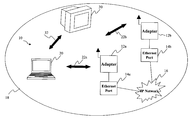
- FIG. 1A is a perspective view of a system for providing Ethernet connectivity over an ultra-wideband (UWB) link according to various aspects of the present disclosure.
- UWB ultra-wideband
- FIG. 1B is a perspective view of an adapter and Ethernet port that may be implemented in the system of FIG. 1A ;
- FIG. 2 is a perspective view of alternative system that utilizes an IP telephone for providing Ethernet connectivity over an UWB link;
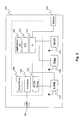
- FIG. 3 is a simplified diagrammatic view of a laptop computer including hardware and software for supporting various wired and wireless technologies
- FIGS. 4A and 4B are diagrammatic views of a plurality of frequency bands in an UWB system, and a plurality of successive superframes being transmitted on an UWB channel, respectively;
- FIG. 5 is a flowchart of a method for providing Ethernet connectivity over an UWB link that may be implemented in the systems of FIGS. 1 and 2 .
- the present invention relates generally to transmission and encryption systems. It is understood, however, that the following disclosure provides many different embodiments, or examples, for implementing different features of the invention. Specific examples of components and arrangements are described below to simplify the present disclosure. These are, of course, merely examples and are not intended to be limiting.
- a system 10 is an example of a communications network that can benefit from one or more embodiments of the present disclosure.
- the system 10 includes a wireless local area network (WLAN) and/or wireless personal area network (WPAN).
- WLAN wireless local area network
- WPAN wireless personal area network
- the system 10 may be implemented as an ultra wideband (UWB) system.
- the UWB system utilizes an unlicensed frequency spectrum between 3.1 and 10.6 GHz which is divided into fourteen (14) bands, each with a bandwidth of 528 MHz. Accordingly, the UWB system is capable of providing data transmission speeds of up to 1 Gbps or more for short range (e.g., a few meters) wireless communications.
- the UWB system may utilize an orthogonal frequency-division multiplexing (OFDM) scheme for transmitting information.
- OFDM is a form of wireless multi-carrier modulation wherein carrier spacing is selected so that each sub-carrier is orthogonal to the other sub-carriers. This orthogonality avoids adjacent channel interference and prevents the demodulators from seeing frequencies other than their own.
- the OFDM signal includes a plurality of sub-carriers, each sub-carrier is modulated with a conventional modulation scheme (e.g., quadrature amplitude modulation).
- the OFDM signal includes 128 sub-carriers (also referred to as tones) that are used per band, of which, 100 are data sub-carriers, 12 are for pilot information, 10 are guard tones, and 6 are null tones carrying no information.
- 128 sub-carriers also referred to as tones
- 100 are data sub-carriers
- 12 are for pilot information
- 10 are guard tones
- 6 are null tones carrying no information.
- the system 10 includes one or more Ethernet adapters 12 a , 12 b each directly coupled to a wired Gigabyte Ethernet port 14 a , 14 b .
- the Ethernet port 14 a , 14 b provides connectivity to a network 16 such as the Internet.
- the Ethernet port 14 a , 14 b utilizes a Transmission Control Protocol/Internet Protocol (TCP/IP) for exchanging data.
- TCP/IP Transmission Control Protocol/Internet Protocol
- the Ethernet port 14 a , 14 b is configured to provide data transmission speeds of up to 1 Gbps.
- the Ethernet port 14 a , 14 b provides a power supply connection for powering the adapter 12 a , 12 b and thus, no additional wiring is needed for the adapter.
- the adapter 12 a , 12 b bridges Ethernet connectivity over an UWB link to cover the local area 18 with high speed wireless Internet connectivity. Even though the disclosed embodiment provides Gigabyte Ethernet connectivity over the UWB link, it is understood that the adapter may alternatively be used to provide wireless connectivity of future technologies that require high bandwidth.
- the adapter 12 a , 12 b provides wireless Internet connectivity to a laptop computer 20 that is within a local area 18 (e.g., a few meters). Even though one laptop computer 20 is shown, it is understood that the adapter 12 a , 12 b may provide wireless Internet connectivity to more than one laptop computer and/or desktop computer within the local area 18 .
- the adapter 12 a , 12 b communicates 22 a , 22 b with the laptop computer 20 on a radio channel in the UWB frequency spectrum.
- the laptop computer 20 is enabled with TCP/IP stacks over its UWB link as will be described later.
- the adapter 12 a , 12 b includes an UWB transceiver for wirelessly transmitting and/or receiving OFDM modulated data to and from UWB enabled devices such as the laptop computer 20 .
- the UWB transceiver may be implemented as a chip providing a radio frequency (RF) transceiver.
- the adapter 12 a , 12 b further includes a baseband Physical (PHY) Layer that is capable of data transmission speeds of up to 1 Gbps.
- the adapter 12 a , 12 b further includes a Media Access Control (MAC) Layer for providing network timing, addressing, and channel access control mechanisms for the PHY Layer.
- the PHY and MAC Layers may be configured in compliance with standards such as the WiMedia or ECMA-368/369.
- the PHY and MAC Layers may be combined in an integrated circuit (IC).
- the adapter 12 may further include an adaptation layer that allows the MAC layer to interface with the TCP/IP protocol stack. As such, the adapter 12 a , 12 b is able to take advantage of the high data transmission speed provided by the Gigabyte Ethernet port 14 a , 14 b .
- These various components may be provided in a chipset available at WiQuest Communications, Inc., 915 Enterprise Blvd., Suite 200, Allen, Tex., 75013.
- the system 10 may include other UWB enabled devices within the local area 18 , that wirelessly communicate with the laptop computer 20 in the UWB spectrum.
- a display device 30 may wireless communicate with the laptop computer 20 over an UWB link 32 .
- the laptop computer 20 is configured to transmit video signals to the display device 30 over the UWB link 32 .
- the local area 18 may also be supported by other types of wireless technologies that operate in licensed and unlicensed frequency bands that overlap with the UWB spectrum.
- the adapter 12 includes firmware for monitoring the available channels in the UWB spectrum to determine which channel has the least amount of traffic or usage. The adapter 12 is able to switch channels and notify the laptop computer 20 of the switch in order to maximize throughput as will be described later.
- an adapter 40 for connecting to the wired Gigabyte Ethernet port 14 of FIG. 1A .
- an establishment such as an office building may include many Ethernet ports 14 located throughout the office.
- the adapter 40 provides wireless Ethernet connectivity over an UWB link to UWB-enabled devices within communication range.
- the Ethernet port 14 may be located on a wall outlet 42 and includes a connector 44 such as a female jack for connecting to the network 16 ( FIG. 1A ) as was discussed above.
- the adapter 40 may include a housing 46 having a connector 48 , such as a male plug, configured to mate 50 with the connector 44 on the wall outlet 42 .
- the adapter 40 may include a processor 52 for receiving data from the Ethernet port 14 in a first format, and processing and converting the data to a second format suitable for transmitting over the UWB link.
- the data transmission over the UWB link may be secured by encryption or other suitable techniques.
- the processor 52 may receive data from an UWB-enabled device over the UWB link, and may process and covert the data for transmitting over the network 16 ( FIG. 1A ).
- the processor 52 may include PHY and MAC layers as was described above.
- the adapter 40 may further include an RF radio 54 coupled to an antenna 56 for transmitting data over the UWB link. Further, a power signal is also provided by the Ethernet port 14 to power the processor 52 and radio 54 . As such, the adapter 40 does not require additional wiring for power connections.
- FIG. 2 illustrated is a perspective view of an alternative system 200 for providing Ethernet connectivity utilizing an IP telephone 202 . Similar features in FIGS. 1 and 2 are numbered the same for simplicity and clarity.
- the IP telephone 202 is configured with hardware and software to support Voice over Internet Protocol (VoIP) technology. VoIP is known in the art and thus, not described in detail herein.
- VoIP Voice over Internet Protocol
- the IP telephone 202 includes an Ethernet connector for connecting to a wired Ethernet port such as a wired Gigabyte Ethernet port 14 .
- the wired Gigabyte Ethernet port is coupled to a network such as the Internet.
- the IP telephone 202 further includes a TCP/IP enabled UWB bridge similar to the Ethernet adapter 12 of FIG. 1 .
- the IP telephone 202 is capable of providing wireless Internet connectivity over a UWB link 204 at data transmission speeds of up to 1 Gbps.
- the IP telephone 202 is typically disposed on a table 206 such that the UWB radio of the IP telephone is near a laptop computer 20 .
- the IP telephone 202 provides for a more reliable and better wireless connectivity to the laptop computer 20 .
- the laptop computer 300 may be utilized in the systems of FIGS. 1 and 2 .
- the laptop computer 300 includes an operating system (OS)/applications 302 for coordinating and controlling various components of the laptop computer.
- OS operating system
- the laptop computer 300 includes a USB port 304 for interfacing with and connecting to various peripherals such as a keyboard, mouse, printer, scanner, and other USB devices.
- the USB port 304 may be coupled to a USB controller or router 306 .
- the laptop computer 300 includes various device drivers such as a printer driver 308 for operating a printer (not shown) that is connected via the USB port 304 .
- the laptop computer 300 further includes an Ethernet port 310 for interfacing with and connecting to a network such as the Internet via wired Gigabyte Ethernet technology.
- the laptop computer 300 also includes a TCP/IP stack 312 , 314 for supporting data exchange in TCP/IP standard protocol.
- the laptop computer 300 may further include an Edge subsystem 320 and WiFi subsystem 322 for supporting wireless communications with Edge and WiFi technology known in the art.
- the Edge and WiFi subsystems 320 , 322 are linked to the TCP/IP stack 312 , 314 to provide wireless Internet connectivity to the laptop computer 300 .
- these wireless technologies have limited bandwidth and thus, the data transmissions speeds of these technologies are much slower than the available speeds provided by Gigabyte Ethernet technology.
- the laptop computer 300 further includes an UWB subsystem 330 for wirelessly communicating with the Ethernet adapter 12 of FIG. 1A , the adapter plug 40 of FIG. 1B , or the IP telephone 202 of FIG. 2 .
- the Ethernet adapters and IP telephone may be coupled to a wired Gigabyte Ethernet port which provides connectivity to the Internet.
- the Ethernet adapters and IP telephone are configured to provide data transmission speeds of up to 1 Gbps on a radio channel in the UWB spectrum.
- the UWB subsystem 330 may connect to the laptop computer via an add-in board inserted into an expansion slot.
- the UWB subsystem 330 includes an RF transceiver for wirelessly receiving and/or transmitting OFDM modulated data from and to the adapters or the IP telephone.
- the UWB subsystem 330 further includes PHY and MAC Layers that may be similar to the one described for the Ethernet adapter of FIG. 1A .
- the UWB subsystem 330 is linked to the TCP/IP stack 312 , 314 such that the laptop computer 300 is capable of wireless Internet connectivity over the UWB link. In this way, the laptop computer 300 can take full advantage of the high data transmission speeds of Gigabyte Ethernet technology for applications such as streaming video or other applications that require high bandwidth.
- the UWB subsystem 330 may be linked to a wireless USB driver 332 known in the art such that the laptop computer can control and operate USB devices that are coupled to or enabled with UWB links.
- FIGS. 4A and 4B illustrated are diagrammatic views of a plurality of frequency bands in an UWB system that are available for communication between UWB enabled devices, and a plurality of successive superframes being transmitted on a radio channel within the UWB system, respectively.
- the PHY layer provides that the UWB spectrum 400 is divided into fourteen (14) bands 401 - 404 , each band having a bandwidth of about 528 MHz.
- the fourteen bands are further defined into five band groups, of which, four band groups each comprise three bands and one band group comprises two bands.
- the PHY Layer defines four time frequency codes (TFC) using time frequency interleaving (TFI) and three TFC using fixed frequency interleaving (FFI), and thus, the PHY Layer provides support for up to seven channels per band.
- TFC time frequency interleaving
- FFI fixed frequency interleaving
- the PHY Layer defines two TFC using FFI. Accordingly, a total of thirty channels are specified in the PHY Layer.
- the UWB system has a limited interference range with other wireless technologies and includes more available channels for communication.
- the UWB system utilizes an orthogonal frequency-division multiplexing (OFDM) scheme for transmitting information.
- the OFDM signal includes 128 sub-carriers (also referred to as tones) that are used per band, of which, 100 are data sub-carriers, 12 are for pilot information, 10 are guard tones, and 6 are null tones carrying no information.
- successive superframes (e.g., N ⁇ 1, N, N+1, etc.) 450 are shown being transmitted over a time period on a channel 455 in the UWB spectrum.
- a superframe is a periodic time interval used to coordinate frame transmissions between devices in the UWB system.
- Each superframe includes a total of 256 time slots (also referred to as medium access slots (MAS)), each time slot having a duration of 256 ⁇ s.
- MAS medium access slots
- Each superframe starts with a beacon period 460 occupying several time slots in which communicating devices synchronize with one another. That is, all devices communicating within a piconet must synchronize their beacon period starting time 465 with one another.
- the beacon period is also used for creating time slot reservations (e.g., distributed reservation protocol (DRP)) for the various devices in the UWB system, and for conveying management and control information using information elements (IE).
- DRP distributed reservation protocol
- IE information elements
- the Ethernet adapter 12 of FIG. 1A , adapter plug 40 of FIG. 1B , or IP telephone 202 of FIG. 2 may transmit a beacon period 460 at the beginning of each superframe 450 to coordinate communications with UWB enabled devices within radio range such as the laptop computer 300 of FIG. 3 .
- the beacon period 460 includes information regarding which time slots in the data period may be reserved for transmitting and receiving data to and from the laptop computer as well as management and control information.
- the adapter may reserve several time slots for scanning the UWB system in order to monitor the other channels for traffic or usage.
- the laptop computer may synchronize its beacon period 460 to the adapter's beacon in the selected channel. As such, data exchange (during the data period 470 ) between the adapter and laptop computer can begin over the selected channel.
- a flowchart of a method 500 for providing wireless Ethernet connectivity over a UWB link may be implemented by the Ethernet adapter 12 of FIG. 1A , adapter plug 40 of FIG. 1B , or the UWB bridge of the IP telephone 202 of FIG. 2 .
- the method 500 may be implemented as firmware provided with the MAC Layer.
- the method 500 begins with step 502 in which the adapter determines, from a plurality of channels in an UWB system, a preferred channel for communicating over the UWB link.
- the preferred channel may be selected from a variety of factors. For example, the preferred channel may be selected as the channel with the least amount of usage or traffic.
- the preferred channel may be selected as the channel with a good signal-to-noise ratio. Further, the preferred channel may be selected from a combination of factors.
- the method 500 continues with step 504 in which the adapter establishes an UWB link over the preferred channel that was determined from the previous step 502 . As such, the adapter establishes wireless connectivity with a laptop computer over its UWB link and/or other UWB enabled device and begins exchanging data (e.g., TCP/IP) over the preferred channel.
- data e.g., TCP/IP
- the method 500 continues with step 506 in which the adapter periodically monitors the plurality of channels to decide whether to switch channels for data transmission.
- the adapter may reserve several time slots in the data period to listen to all the other available channels in the UWB system to determine if another channel is preferred for the UWB link. If no, the method 500 continues with step 508 in which the adapter continues with data transmission on the current channel.
- the method 500 continues with step 510 in which the adapter switches to the new channel that is preferred and notifies the laptop computer of the switch by a switching mechanism.
- the adapter may include a channel change information element (IE) in a beacon period sent on the current channel.
- the channel change IE includes a new channel number.
- the adapter may further include a channel change count field to a remaining number of superframes before it switches to the new channel. As such, the channel change count field is decremented by one following each successive superframe.
- the method 500 repeats step 504 in which the adapter establishes the UWB link and begins data transmission on the new channel on the next superframe.
- Each of the above-mentioned components can be implemented as computer software, electrical logic, or combinations thereof. Also, although components are shown separately in the figures, in some embodiments one or more of the components on either side of the wireless link may be combined into a single integrated circuit device, or a group of devices.
- the UWB system disclosed herein has a limited interference range with other wireless technologies due to more radio channels being available for communication and thus, does not have to share channels.
- the wireless Ethernet adapter includes low power CMOS integrated circuits so that the adapter can be powered via the Ethernet port.
Landscapes
- Engineering & Computer Science (AREA)
- Computer Networks & Wireless Communication (AREA)
- Signal Processing (AREA)
- Mobile Radio Communication Systems (AREA)
Abstract
Description
Claims (14)
Priority Applications (1)
| Application Number | Priority Date | Filing Date | Title |
|---|---|---|---|
| US12/197,184 US8577403B2 (en) | 2007-08-22 | 2008-08-22 | Wireless ethernet adapter |
Applications Claiming Priority (2)
| Application Number | Priority Date | Filing Date | Title |
|---|---|---|---|
| US95722407P | 2007-08-22 | 2007-08-22 | |
| US12/197,184 US8577403B2 (en) | 2007-08-22 | 2008-08-22 | Wireless ethernet adapter |
Publications (2)
| Publication Number | Publication Date |
|---|---|
| US20090053999A1 US20090053999A1 (en) | 2009-02-26 |
| US8577403B2 true US8577403B2 (en) | 2013-11-05 |
Family
ID=40379009
Family Applications (1)
| Application Number | Title | Priority Date | Filing Date |
|---|---|---|---|
| US12/197,184 Expired - Fee Related US8577403B2 (en) | 2007-08-22 | 2008-08-22 | Wireless ethernet adapter |
Country Status (6)
| Country | Link |
|---|---|
| US (1) | US8577403B2 (en) |
| EP (1) | EP2183857A4 (en) |
| JP (2) | JP2010537587A (en) |
| KR (1) | KR101070940B1 (en) |
| CN (1) | CN101809884B (en) |
| WO (1) | WO2009026573A2 (en) |
Cited By (2)
| Publication number | Priority date | Publication date | Assignee | Title |
|---|---|---|---|---|
| US9137849B1 (en) * | 2008-12-09 | 2015-09-15 | Cypress Semiconductor Corporation | Dynamically switching communication modes in multi-standard wireless communication devices |
| US20210400534A1 (en) * | 2020-06-18 | 2021-12-23 | 5321 Innovation Labs LLC | Bridge system for connecting a private computer network to a public computer network |
Families Citing this family (9)
| Publication number | Priority date | Publication date | Assignee | Title |
|---|---|---|---|---|
| GB0801535D0 (en) * | 2008-01-28 | 2008-03-05 | Fujitsu Lab Of Europ Ltd | Communications systems |
| US20110143768A1 (en) * | 2009-12-14 | 2011-06-16 | Lane Sean L | Methods and apparatus related to region-specific mobile device and infrastructure detection, analysis and display |
| US10032120B2 (en) * | 2010-09-28 | 2018-07-24 | Symbol Technologies, Llc | Method and apparatus for workforce management |
| US9585097B2 (en) | 2014-03-21 | 2017-02-28 | Apple Inc. | Synchronized low-energy detection technique |
| CN111246391A (en) * | 2020-01-13 | 2020-06-05 | 上海思立微电子科技有限公司 | Wireless data transmission method, device and equipment |
| KR102936189B1 (en) * | 2020-03-19 | 2026-03-09 | 삼성전자주식회사 | Electronic apparatus using a pluality of communication shcemes and method for controlling thereof |
| CN113055873B (en) * | 2021-03-11 | 2022-09-09 | Oppo广东移动通信有限公司 | Inter-device identification method, device, electronic device and storage medium |
| JP2022149811A (en) * | 2021-03-25 | 2022-10-07 | 京セラドキュメントソリューションズ株式会社 | Image forming apparatus, image forming method and image forming program |
| WO2023043236A1 (en) * | 2021-09-15 | 2023-03-23 | Samsung Electronics Co., Ltd. | Method and system for collision avoidance in ultra-wide band network |
Citations (14)
| Publication number | Priority date | Publication date | Assignee | Title |
|---|---|---|---|---|
| JP2002335252A (en) | 2001-05-08 | 2002-11-22 | Sony Corp | Wireless transmission method, wireless communication system, method for managing wireless network, transmitting device, receiving device, transceiver device |
| JP2003087855A (en) | 2001-09-13 | 2003-03-20 | Ntt Docomo Inc | Channel allocation method, wireless communication system using the same, base station device, control station device, and mobile station device |
| JP2003249935A (en) | 2002-02-26 | 2003-09-05 | Oki Electric Ind Co Ltd | Radio lan system |
| US6757522B1 (en) * | 2000-12-11 | 2004-06-29 | Cisco Technology, Inc. | Technique for determining carrier-to-noise ratio of selected channels in an access network |
| US20050070320A1 (en) * | 2003-09-26 | 2005-03-31 | Dent Paul W. | Method and apparatus to reduce dispatch delays in dispatch communication networks |
| US20050255878A1 (en) | 2004-05-17 | 2005-11-17 | Nokia Corporation | Mobile terminal having UWB and cellular capability |
| US20060252418A1 (en) * | 2005-05-06 | 2006-11-09 | Quinn Liam B | Systems and methods for RF spectrum management |
| JP2006332835A (en) | 2005-05-24 | 2006-12-07 | Toshiba Corp | Wireless communication terminal equipped with multiple wireless communication units |
| US20070054618A1 (en) * | 2005-09-08 | 2007-03-08 | Lewis Jonathan F | System and method for wireless access point with integrated emergency devices |
| US20070077819A1 (en) | 2005-10-05 | 2007-04-05 | Mitel Networks Corporation | Midspan power delivery system for reduced emissions |
| US20080107098A1 (en) * | 2006-11-08 | 2008-05-08 | Paul Spencer | Multislot-mode automatic frequency correction apparatus, systems, and methods |
| US20080155097A1 (en) * | 2006-12-21 | 2008-06-26 | Motorola, Inc. | Centralized processing system for connect homes devices |
| US7729659B2 (en) * | 2006-06-16 | 2010-06-01 | Mitsubishi Electric Research Laboratories, Inc. | Method for signaling quality of range estimates in UWB devices |
| US7756101B2 (en) * | 2005-12-30 | 2010-07-13 | Nokia Corporation | Efficient resolution of relinquishment requests in a wireless communications network |
Family Cites Families (3)
| Publication number | Priority date | Publication date | Assignee | Title |
|---|---|---|---|---|
| AU2002332279A1 (en) * | 2002-08-30 | 2004-03-29 | Fujitsu Limited | Communication method, communication device, and communication system |
| KR100647988B1 (en) * | 2004-06-08 | 2006-11-23 | 삼성전자주식회사 | System for radio resource assignment in multi band OFDM |
| GB2429875B (en) * | 2005-09-05 | 2008-03-12 | Toshiba Res Europ Ltd | Improved broadband carrier frequency selection |
-
2008
- 2008-08-22 US US12/197,184 patent/US8577403B2/en not_active Expired - Fee Related
- 2008-08-22 WO PCT/US2008/074121 patent/WO2009026573A2/en not_active Ceased
- 2008-08-22 JP JP2010522095A patent/JP2010537587A/en not_active Withdrawn
- 2008-08-22 KR KR1020107006233A patent/KR101070940B1/en not_active Expired - Fee Related
- 2008-08-22 CN CN200880103894XA patent/CN101809884B/en not_active Expired - Fee Related
- 2008-08-22 EP EP08827664.7A patent/EP2183857A4/en not_active Withdrawn
-
2013
- 2013-07-26 JP JP2013155903A patent/JP5559403B2/en not_active Expired - Fee Related
Patent Citations (14)
| Publication number | Priority date | Publication date | Assignee | Title |
|---|---|---|---|---|
| US6757522B1 (en) * | 2000-12-11 | 2004-06-29 | Cisco Technology, Inc. | Technique for determining carrier-to-noise ratio of selected channels in an access network |
| JP2002335252A (en) | 2001-05-08 | 2002-11-22 | Sony Corp | Wireless transmission method, wireless communication system, method for managing wireless network, transmitting device, receiving device, transceiver device |
| JP2003087855A (en) | 2001-09-13 | 2003-03-20 | Ntt Docomo Inc | Channel allocation method, wireless communication system using the same, base station device, control station device, and mobile station device |
| JP2003249935A (en) | 2002-02-26 | 2003-09-05 | Oki Electric Ind Co Ltd | Radio lan system |
| US20050070320A1 (en) * | 2003-09-26 | 2005-03-31 | Dent Paul W. | Method and apparatus to reduce dispatch delays in dispatch communication networks |
| US20050255878A1 (en) | 2004-05-17 | 2005-11-17 | Nokia Corporation | Mobile terminal having UWB and cellular capability |
| US20060252418A1 (en) * | 2005-05-06 | 2006-11-09 | Quinn Liam B | Systems and methods for RF spectrum management |
| JP2006332835A (en) | 2005-05-24 | 2006-12-07 | Toshiba Corp | Wireless communication terminal equipped with multiple wireless communication units |
| US20070054618A1 (en) * | 2005-09-08 | 2007-03-08 | Lewis Jonathan F | System and method for wireless access point with integrated emergency devices |
| US20070077819A1 (en) | 2005-10-05 | 2007-04-05 | Mitel Networks Corporation | Midspan power delivery system for reduced emissions |
| US7756101B2 (en) * | 2005-12-30 | 2010-07-13 | Nokia Corporation | Efficient resolution of relinquishment requests in a wireless communications network |
| US7729659B2 (en) * | 2006-06-16 | 2010-06-01 | Mitsubishi Electric Research Laboratories, Inc. | Method for signaling quality of range estimates in UWB devices |
| US20080107098A1 (en) * | 2006-11-08 | 2008-05-08 | Paul Spencer | Multislot-mode automatic frequency correction apparatus, systems, and methods |
| US20080155097A1 (en) * | 2006-12-21 | 2008-06-26 | Motorola, Inc. | Centralized processing system for connect homes devices |
Non-Patent Citations (2)
Cited By (4)
| Publication number | Priority date | Publication date | Assignee | Title |
|---|---|---|---|---|
| US9137849B1 (en) * | 2008-12-09 | 2015-09-15 | Cypress Semiconductor Corporation | Dynamically switching communication modes in multi-standard wireless communication devices |
| US10165425B2 (en) | 2008-12-09 | 2018-12-25 | Cypress Semiconductor Corporation | Dynamically switching communication modes in multi-standard wireless communication devices |
| US20210400534A1 (en) * | 2020-06-18 | 2021-12-23 | 5321 Innovation Labs LLC | Bridge system for connecting a private computer network to a public computer network |
| US11849353B2 (en) * | 2020-06-18 | 2023-12-19 | 5321 Innovation Labs LLC | Bridge system for connecting a private computer network to a public computer network |
Also Published As
| Publication number | Publication date |
|---|---|
| JP2014014086A (en) | 2014-01-23 |
| KR101070940B1 (en) | 2011-10-06 |
| KR20100057661A (en) | 2010-05-31 |
| CN101809884B (en) | 2012-12-26 |
| JP5559403B2 (en) | 2014-07-23 |
| WO2009026573A3 (en) | 2009-04-16 |
| CN101809884A (en) | 2010-08-18 |
| EP2183857A4 (en) | 2017-03-15 |
| EP2183857A2 (en) | 2010-05-12 |
| WO2009026573A2 (en) | 2009-02-26 |
| JP2010537587A (en) | 2010-12-02 |
| US20090053999A1 (en) | 2009-02-26 |
Similar Documents
| Publication | Publication Date | Title |
|---|---|---|
| US8577403B2 (en) | Wireless ethernet adapter | |
| US6519460B1 (en) | Resource management in uncoordinated frequency hopping system | |
| US7583644B2 (en) | Wireless communication apparatus, wireless communication method, and computer program | |
| Dhawan | Analogy of promising wireless technologies on different frequencies: Bluetooth, wifi, and wimax | |
| US8169980B2 (en) | Methods and apparatuses for interworking | |
| US9668299B2 (en) | Multi-mode WLAN/PAN MAC | |
| JP3968514B2 (en) | Wireless communication system, wireless communication apparatus, wireless communication method, and computer program | |
| US7454218B2 (en) | Method of band multiplexing to improve system capacity for a multi-band communication system | |
| CN101682563A (en) | Improved use of network capacity | |
| WO2007133424A2 (en) | Arrangement for synchronizing access points in wlan using direct-sequence spread spectrum signaling | |
| US20160007335A1 (en) | Slot-based d2d communication method and apparatus | |
| JP4523216B2 (en) | Resource management for untuned frequency hopping systems | |
| JP5470652B2 (en) | Wireless communication system and interference prevention method | |
| WO2007018366A1 (en) | Channel allocation method between heterogeneous wireless networks and wireless network apparatus providing the same | |
| JP3703087B2 (en) | Wireless data communication system | |
| WO2019212503A1 (en) | System, methods, and apparatus to facilitate channelization | |
| JP5649176B2 (en) | Wireless communication system and interference prevention method |
Legal Events
| Date | Code | Title | Description |
|---|---|---|---|
| AS | Assignment |
Owner name: WIQUEST COMMUNICATIONS, INC., TEXAS Free format text: ASSIGNMENT OF ASSIGNORS INTEREST;ASSIGNORS:SHOEMAKE, MATTHEW;CHRISTISON, GREG;REEL/FRAME:021432/0288;SIGNING DATES FROM 20080821 TO 20080822 Owner name: WIQUEST COMMUNICATIONS, INC., TEXAS Free format text: ASSIGNMENT OF ASSIGNORS INTEREST;ASSIGNORS:SHOEMAKE, MATTHEW;CHRISTISON, GREG;SIGNING DATES FROM 20080821 TO 20080822;REEL/FRAME:021432/0288 |
|
| AS | Assignment |
Owner name: TRIPLEPOINT CAPITAL LLC, CALIFORNIA Free format text: SECURITY AGREEMENT;ASSIGNOR:WIQUEST COMMUNICATIONS, INC.;REEL/FRAME:021858/0798 Effective date: 20081112 Owner name: TRIPLEPOINT CAPITAL LLC,CALIFORNIA Free format text: SECURITY AGREEMENT;ASSIGNOR:WIQUEST COMMUNICATIONS, INC.;REEL/FRAME:021858/0798 Effective date: 20081112 |
|
| AS | Assignment |
Owner name: TRIPLEPOINT CAPITAL LLC, CALIFORNIA Free format text: AFFIDAVIT OF FORECLOSURE;ASSIGNOR:WIQUEST COMMUNICATIONS, INC.;REEL/FRAME:022360/0771 Effective date: 20090126 Owner name: TRIPLEPOINT CAPITAL LLC,CALIFORNIA Free format text: AFFIDAVIT OF FORECLOSURE;ASSIGNOR:WIQUEST COMMUNICATIONS, INC.;REEL/FRAME:022360/0771 Effective date: 20090126 |
|
| AS | Assignment |
Owner name: QUALCOMM INCORPORATED, CALIFORNIA Free format text: ASSIGNMENT OF ASSIGNORS INTEREST;ASSIGNOR:TRIPLEPOINT CAPITAL LLC;REEL/FRAME:022370/0651 Effective date: 20090126 Owner name: QUALCOMM INCORPORATED,CALIFORNIA Free format text: ASSIGNMENT OF ASSIGNORS INTEREST;ASSIGNOR:TRIPLEPOINT CAPITAL LLC;REEL/FRAME:022370/0651 Effective date: 20090126 |
|
| STCF | Information on status: patent grant |
Free format text: PATENTED CASE |
|
| FPAY | Fee payment |
Year of fee payment: 4 |
|
| MAFP | Maintenance fee payment |
Free format text: PAYMENT OF MAINTENANCE FEE, 8TH YEAR, LARGE ENTITY (ORIGINAL EVENT CODE: M1552); ENTITY STATUS OF PATENT OWNER: LARGE ENTITY Year of fee payment: 8 |
|
| FEPP | Fee payment procedure |
Free format text: MAINTENANCE FEE REMINDER MAILED (ORIGINAL EVENT CODE: REM.); ENTITY STATUS OF PATENT OWNER: LARGE ENTITY |
|
| LAPS | Lapse for failure to pay maintenance fees |
Free format text: PATENT EXPIRED FOR FAILURE TO PAY MAINTENANCE FEES (ORIGINAL EVENT CODE: EXP.); ENTITY STATUS OF PATENT OWNER: LARGE ENTITY |
|
| STCH | Information on status: patent discontinuation |
Free format text: PATENT EXPIRED DUE TO NONPAYMENT OF MAINTENANCE FEES UNDER 37 CFR 1.362 |
|
| FP | Lapsed due to failure to pay maintenance fee |
Effective date: 20251105 |