US8577266B2 - Image forming apparatus comprising a detection member and tension applying member facing each other - Google Patents
Image forming apparatus comprising a detection member and tension applying member facing each other Download PDFInfo
- Publication number
- US8577266B2 US8577266B2 US12/862,440 US86244010A US8577266B2 US 8577266 B2 US8577266 B2 US 8577266B2 US 86244010 A US86244010 A US 86244010A US 8577266 B2 US8577266 B2 US 8577266B2
- Authority
- US
- United States
- Prior art keywords
- tension applying
- endless belt
- image forming
- forming apparatus
- peripheral surface
- Prior art date
- Legal status (The legal status is an assumption and is not a legal conclusion. Google has not performed a legal analysis and makes no representation as to the accuracy of the status listed.)
- Expired - Fee Related, expires
Links
Images


Classifications
-
- G—PHYSICS
- G03—PHOTOGRAPHY; CINEMATOGRAPHY; ANALOGOUS TECHNIQUES USING WAVES OTHER THAN OPTICAL WAVES; ELECTROGRAPHY; HOLOGRAPHY
- G03G—ELECTROGRAPHY; ELECTROPHOTOGRAPHY; MAGNETOGRAPHY
- G03G15/00—Apparatus for electrographic processes using a charge pattern
- G03G15/50—Machine control of apparatus for electrographic processes using a charge pattern, e.g. regulating differents parts of the machine, multimode copiers, microprocessor control
- G03G15/5054—Machine control of apparatus for electrographic processes using a charge pattern, e.g. regulating differents parts of the machine, multimode copiers, microprocessor control by measuring the characteristics of an intermediate image carrying member or the characteristics of an image on an intermediate image carrying member, e.g. intermediate transfer belt or drum, conveyor belt
- G03G15/5058—Machine control of apparatus for electrographic processes using a charge pattern, e.g. regulating differents parts of the machine, multimode copiers, microprocessor control by measuring the characteristics of an intermediate image carrying member or the characteristics of an image on an intermediate image carrying member, e.g. intermediate transfer belt or drum, conveyor belt using a test patch
-
- G—PHYSICS
- G03—PHOTOGRAPHY; CINEMATOGRAPHY; ANALOGOUS TECHNIQUES USING WAVES OTHER THAN OPTICAL WAVES; ELECTROGRAPHY; HOLOGRAPHY
- G03G—ELECTROGRAPHY; ELECTROPHOTOGRAPHY; MAGNETOGRAPHY
- G03G15/00—Apparatus for electrographic processes using a charge pattern
- G03G15/01—Apparatus for electrographic processes using a charge pattern for producing multicoloured copies
- G03G15/0105—Details of unit
- G03G15/0131—Details of unit for transferring a pattern to a second base
-
- G—PHYSICS
- G03—PHOTOGRAPHY; CINEMATOGRAPHY; ANALOGOUS TECHNIQUES USING WAVES OTHER THAN OPTICAL WAVES; ELECTROGRAPHY; HOLOGRAPHY
- G03G—ELECTROGRAPHY; ELECTROPHOTOGRAPHY; MAGNETOGRAPHY
- G03G15/00—Apparatus for electrographic processes using a charge pattern
- G03G15/01—Apparatus for electrographic processes using a charge pattern for producing multicoloured copies
- G03G15/0142—Structure of complete machines
- G03G15/0178—Structure of complete machines using more than one reusable electrographic recording member, e.g. one for every monocolour image
- G03G15/0194—Structure of complete machines using more than one reusable electrographic recording member, e.g. one for every monocolour image primary transfer to the final recording medium
-
- G—PHYSICS
- G03—PHOTOGRAPHY; CINEMATOGRAPHY; ANALOGOUS TECHNIQUES USING WAVES OTHER THAN OPTICAL WAVES; ELECTROGRAPHY; HOLOGRAPHY
- G03G—ELECTROGRAPHY; ELECTROPHOTOGRAPHY; MAGNETOGRAPHY
- G03G15/00—Apparatus for electrographic processes using a charge pattern
- G03G15/14—Apparatus for electrographic processes using a charge pattern for transferring a pattern to a second base
- G03G15/16—Apparatus for electrographic processes using a charge pattern for transferring a pattern to a second base of a toner pattern, e.g. a powder pattern, e.g. magnetic transfer
- G03G15/1605—Apparatus for electrographic processes using a charge pattern for transferring a pattern to a second base of a toner pattern, e.g. a powder pattern, e.g. magnetic transfer using at least one intermediate support
- G03G15/1615—Apparatus for electrographic processes using a charge pattern for transferring a pattern to a second base of a toner pattern, e.g. a powder pattern, e.g. magnetic transfer using at least one intermediate support relating to the driving mechanism for the intermediate support, e.g. gears, couplings, belt tensioning
-
- G—PHYSICS
- G03—PHOTOGRAPHY; CINEMATOGRAPHY; ANALOGOUS TECHNIQUES USING WAVES OTHER THAN OPTICAL WAVES; ELECTROGRAPHY; HOLOGRAPHY
- G03G—ELECTROGRAPHY; ELECTROPHOTOGRAPHY; MAGNETOGRAPHY
- G03G2215/00—Apparatus for electrophotographic processes
- G03G2215/00025—Machine control, e.g. regulating different parts of the machine
- G03G2215/00029—Image density detection
- G03G2215/00059—Image density detection on intermediate image carrying member, e.g. transfer belt
-
- G—PHYSICS
- G03—PHOTOGRAPHY; CINEMATOGRAPHY; ANALOGOUS TECHNIQUES USING WAVES OTHER THAN OPTICAL WAVES; ELECTROGRAPHY; HOLOGRAPHY
- G03G—ELECTROGRAPHY; ELECTROPHOTOGRAPHY; MAGNETOGRAPHY
- G03G2215/00—Apparatus for electrophotographic processes
- G03G2215/00025—Machine control, e.g. regulating different parts of the machine
- G03G2215/00029—Image density detection
- G03G2215/00063—Colour
-
- G—PHYSICS
- G03—PHOTOGRAPHY; CINEMATOGRAPHY; ANALOGOUS TECHNIQUES USING WAVES OTHER THAN OPTICAL WAVES; ELECTROGRAPHY; HOLOGRAPHY
- G03G—ELECTROGRAPHY; ELECTROPHOTOGRAPHY; MAGNETOGRAPHY
- G03G2215/00—Apparatus for electrophotographic processes
- G03G2215/01—Apparatus for electrophotographic processes for producing multicoloured copies
- G03G2215/0151—Apparatus for electrophotographic processes for producing multicoloured copies characterised by the technical problem
- G03G2215/0158—Colour registration
Definitions
- the present invention relates to an image forming apparatus.
- the present invention provides an image forming apparatus configured such that even if a detection member is disposed facing an outer peripheral surface of an endless belt at the portion pressed by a tension applying member, the distance between the detection member and the outer peripheral surface of the endless belt is kept.
- An image processing apparatus of a first aspect of the invention is characterized in that the apparatus includes an endless belt that travels circularly by a drive member and has an outer peripheral surface on which an image is formed; a tension applying member around which the endless belt is trained and that applies tension to the endless belt by pressing an inner peripheral surface of the endless belt; a detection member that detects the image formed on the outer peripheral surface of the endless belt; a support member to which the detection member is attached and that movably supports the detection member with respect to an apparatus main body; and a positioning member that positions the detection member with respect to the outer peripheral surface of the endless belt at a portion pressed by the tension applying member.
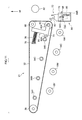
- FIG. 1 is a side elevational view showing a primary transfer unit employed to an image forming apparatus according to an exemplary embodiment of the invention
- FIG. 2 is a side elevational view showing a vicinity of a tension applying roll of the primary transfer unit employed to the image forming apparatus according to the exemplary embodiment of the invention
- FIG. 3 is a perspective view showing a vicinity of the tension applying roll of the primary transfer unit employed to the image forming apparatus according to the exemplary embodiment of the invention
- FIG. 4 is a side elevational view showing the primary transfer unit employed to the image forming apparatus according to the exemplary embodiment of the invention.
- FIG. 5 is a side elevational view showing a vicinity of the tension applying roll of the primary transfer unit employed to the image forming apparatus according to the exemplary embodiment of the invention
- FIG. 6 is a perspective view showing a vicinity of the tension applying roll of the primary transfer unit employed to the image forming apparatus according to the exemplary embodiment of the invention.
- FIG. 7 is a side elevational view showing the primary transfer unit employed to the image forming apparatus according to the exemplary embodiment of the invention.
- FIG. 8 is a side elevational view showing a vicinity of the tension applying roll of the primary transfer unit employed to the image forming apparatus according to the exemplary embodiment of the invention.
- FIG. 9 is a perspective view showing a vicinity of the tension applying roll of the primary transfer unit employed to the image forming apparatus according to the exemplary embodiment of the invention.
- FIG. 10 is a perspective view showing a vicinity of the tension applying roll of the primary transfer unit employed to the image forming apparatus according to the exemplary embodiment of the invention.
- FIG. 11 is a side elevational, view showing the primary transfer unit employed to the image forming apparatus according to the exemplary embodiment of the invention.
- FIG. 12 is a side elevational view showing a vicinity of the tension applying roll of the primary transfer unit employed to the image forming apparatus according to the exemplary embodiment of the invention.
- FIG. 13 is a perspective view showing a vicinity of the tension applying roll of the primary transfer unit employed to the image forming apparatus according to the exemplary embodiment of the invention.
- FIG. 14 is a schematic configuration view showing the image forming apparatus according to the exemplary embodiment of the invention.
- FIG. 1 to FIG. 14 An example an image forming apparatus according to an exemplary embodiment of the present invention will be explained referring to FIG. 1 to FIG. 14 .
- an image processing section 12 which processes an image to image data, is disposed in an apparatus main body 10 A of the image forming apparatus 10 .
- the image processing section 12 processes input image data to gradation data of four colors of yellow (Y), magenta (M), cyan (C), and black (K), and an exposure device 14 , which receives the processed gradation data and exposes an image by a laser beam LB, is disposed at a central portion in the apparatus main body 10 A.
- image forming units 16 Y, 16 M, 16 C, 16 K of yellow (Y), magenta (M), cyan (C), and black (K) are disposed above the exposure device 14 at intervals in a horizontal direction. Note that when it is not necessary to discriminate Y, M, C, K in explanation, they may be explained omitting Y, M, C, K.
- All the four image forming units 16 Y, 16 M, 16 C, 16 K are configured likewise and include columnar image holding members 18 driven in rotation at a predetermined speed, primary charging members 20 for charging outer peripheral surfaces of the image holding members 18 , developing members 22 for making electrostatic latent images, which are formed on the outer peripheral surfaces of the image holding members 18 charged by the image exposure of the exposure device 14 , visible as toner images by developing the electrostatic latent images by toners having predetermined colors, and cleaning blades 24 for cleaning the outer peripheral surfaces of the image holding members 18 . Further, cleaning members 64 are disposed under the columnar charging members 20 in contact the charging members 20 to clean outer peripheral surfaces of the charging members 20 .
- the exposure device 14 is provided with four semiconductor lasers (not shown in the drawings) configured commonly to the four image forming units 16 Y, 16 M, 16 C, 16 K, and laser beams LB-Y, LB-M, LB-C, LB-K are emitted from the semiconductor lasers according to the gradation data.
- the laser beams LB-Y, LB-M, LB-C, LB-K emitted from the semiconductor lasers are radiated to a polygon mirror 26 as a rotary multi-face mirror via a f- ⁇ lens which are not shown in the drawings and are deflection-scanned by the polygon mirror 26 .
- the laser beams LB-Y, LB-M, LB-C, LB-K, which are deflection-scanned by the polygon mirror 26 are scan-exposed to an exposure point on the image holding members 18 from obliquely downward via imaging lens and plural mirrors which are not shown in the drawings.
- the exposure device 14 scan-exposes images on the image holding members 18 from downward, there is a possibility that toners and the like drop onto the exposure device 14 from the developing members 22 and the like of the four image forming units 16 Y, 16 M, 16 C, 16 K located above the exposure device 14 . Accordingly, a periphery of the exposure device 14 is sealed by a rectangular parallelepiped frame 28 .
- Transparent glass windows 30 Y, 30 M, 30 C, 30 K are disposed on the frame 28 to cause the four laser beams LB-Y, LB-M, LB-C, LB-K to pass through the transparent glass windows 30 Y, 30 M, 30 C, 30 K onto the image holding members 18 of the respective image forming units 16 Y, 16 M, 16 C, 16 K.
- a primary transfer unit 21 as an example of a belt unit is disposed above the respective image forming units 16 Y, 16 M, 16 C, 16 K.
- the primary transfer unit 21 includes an intermediate transfer belt 32 as an example of an endless belt, a drive roll 36 around which the intermediate transfer belt 32 is trained and which is driven in rotation and causes the intermediate transfer belt 32 to circularly travel in an arrow direction, a tension applying roll 40 as an example of a tension applying member around which the intermediate transfer belt 32 is trained and by which tension is applied to the intermediate transfer belt 32 , a driven roll 66 disposed above the tension applying roll 40 and driven together with the intermediate transfer belt 32 , and primary transfer rolls 34 Y, 34 M, 34 C, 34 K disposed on an opposite side of image holding members 18 Y, 18 M, 18 C, 18 K with the intermediate transfer belt 32 interposed therebetween.
- a cleaning blade 38 for cleaning an outer peripheral surface the intermediate transfer belt 32 is disposed so as to face the drive roll 36 with the intermediate transfer belt 32 interposed therebetween.
- a support member 72 to which a detection member 70 (refer to FIG. 2 ) for detecting the toner images transferred onto the intermediate transfer belt 32 is attached, is disposed at a position facing the tension applying roll 40 with the intermediate transfer belt 32 interposed therebetween. Note that the primary transfer unit 21 , the detection member 70 , and the like will be described later in detail.
- a secondary transfer roll 42 is disposed on an opposite side of the driven roll 66 with the intermediate transfer belt 32 interposed therebetween.
- the toner images of the respective colors of yellow (Y), magenta (M), cyan (C), black (K), which are transferred onto the intermediate transfer belt 32 in the multiple manner, are transported by the intermediate transfer belt 32 , sandwiched between the driven roll 66 and the secondary transfer roll 42 , and secondarily transferred onto a sheet member P as a recording medium transported along a sheet transport path 56 .
- a fixing unit 44 which fixes the toner images transferred onto the sheet member P to sheet member P by heat and pressure, is disposed at a downstream side in a transport direction of the sheet member P with respect to the secondary transfer roll 42 (hereinafter, simply called a downstream side).
- discharge rolls 46 which discharge the sheet member P onto which the toner images are fixed to a discharge section 48 disposed at an upper portion of the apparatus main body 10 A of the image forming apparatus 10 , are disposed at a downstream side of the fixing unit 44 .
- a sheet feed member 50 on which sheet members P are stacked, is disposed on a lower side of in the apparatus main body 10 A of the image forming apparatus 10 .
- a sheet feed roll 52 which feeds the sheet members P stacked on the sheet feed member 50 to a sheet transport path 56 , is disposed.
- a separation roll 54 which transports the sheet members P by separating them one by one, is disposed at a downstream side of the sheet feed roll 52 .
- an alignment roll 58 for aligning a transport timing is disposed downstream of the separation roll 54 .
- the sheet members P supplied from the sheet feed member 50 are fed to a position (secondary transfer position) where the intermediate transfer belt 32 is caused to come into contact with the secondary transfer roll 42 by the alignment roll 58 which is rotated at a predetermined timing.
- Transport rolls 60 are disposed adjacent to the discharge rolls 46 to transport the sheet member P having one side on which the image is fixed by the fixing unit 44 to a both-side transport path 62 without discharging the sheet member P onto the discharge section 48 by the discharge rolls 46 as it is. Due to this operation, the sheet member P, which is transported along the both-side sheet transport path 62 , is transported to the alignment roll 58 again with a front side and the back side inverted and discharged onto the discharge section 48 after the toner images are transferred and fixed onto the back side of the sheet member P.
- the images are formed on the sheet member P as described below.
- the gradation data of the respective colors are sequentially output from the image processing section 12 to the exposure device 14 , the laser beams.
- LB-Y, LB-M, LB-C, LB-K which are emitted from the exposure device 14 according to the gradation data, are scan-exposed to the outer peripheral surfaces of the image holding members 18 charged by the charging members 20 , thereby forming the electrostatic latent images on the outer peripheral surfaces of the image holding members 18 .
- the electrostatic latent images formed on the image holding members 18 are made visible as the toner images of the respective colors of yellow (Y), magenta (M), cyan (C), black (K) by the developing members 22 Y, 22 M, 22 C, 22 K, respectively.
- the toner images of the respective colors of yellow (Y), magenta (M), cyan (C), black (K), which are formed on the image holding members 18 by the primary transfer rolls 34 of the primary transfer unit 21 disposed throughout above the respective image forming units 16 Y, 16 M, 16 C, 16 K, are transferred onto the circularly traveling intermediate transfer belt 32 in the multiple manner.
- the toner images of the respective colors which are transferred onto the circularly traveling intermediate transfer belt 32 in the multiple manner are secondarily transferred onto the sheet member P by the secondary transfer roll 42 , the sheet member P being transported from the sheet feed member 50 to the sheet transport path 56 at a predetermined timing by the sheet feed roll 52 , the separation roll 54 , and the alignment roll 58 .
- the sheet member P onto which the toner images are transferred is transported to the fixing unit 44 .
- the toner images, which are transferred onto the sheet member P, are fixed onto the sheet member P by the fixing unit 44 and discharged to the discharge section 48 disposed at an upper portion of the apparatus main body 10 A of the image forming apparatus 10 by the discharge rolls 46 after the toner images are fixed on the sheet member P.
- the sheet member P having one side on which an image is fixed by the fixing unit 44 is transported to the both-side transport path 62 via the transport rolls 60 by switching a transport direction without being discharged onto the discharge section 48 by the discharge rolls 46 .
- the front side and the back side of the sheet member P are inverted by transporting the sheet member P along the both-side transport path 62 , and the sheet member P is transported to the alignment roll 58 again.
- the toner images are transferred and fixed onto the back side of the sheet member P, and the sheet member P is discharged onto the discharge section 48 by the discharge rolls 46 after the toner image is fixed and transferred.
- the primary transfer rolls 34 of the respective colors disposed at the primary transfer unit 21 are supported by support members which are not shown in the drawings so that the intermediate transfer belt 32 is pressed to the image holding members 18 . Due to this operation, the toner images of the respective colors formed on the image holding members 18 are transferred onto the intermediate transfer belt 32 .
- both the ends of a rotating shaft 40 A (including a support shaft for supporting the shaft in rotation) of the tension applying roll 40 are rotatably supported by one ends of holding members 80 formed in an L-shape when viewed from the direction of the rotating shaft 40 A (hereinafter, simply called an axial direction).
- projecting sections 80 A which project on opposite sides to the one ends of holding members 80 , are disposed at corners of the holding members 80 and are rotatably supported to frame members which are not shown in the drawings by shaft sections 74 . More specifically, the holding members 80 rotate and move about the shaft sections 74 , and the tension applying roll 40 may move about the shaft sections 74 in an arc shape.
- extremity end sections of compression coil springs 76 as an example of urging members are fixed to the other ends (which are ends extending upward) of the holding members 80 , and base end sections of the compression coil springs 76 are fixed to frame members 78 .
- the holding members 80 rotate and move about the shaft sections 74 , and the compression coil springs 76 urge the other ends of the holding members 80 so that the tension applying roll 40 presses the inner peripheral surface of the intermediate transfer belt 32 . Due to this operation, tension is applied to the intermediate transfer belt 32 in a predetermined range.
- the detection member 70 for detecting the toner images, which are transferred onto the intermediate transfer belt 32 is disposed at a position facing the tension applying roll 40 with the intermediate transfer belt 32 interposed therebetween and is attached to the support member 72 .
- the support member 72 has a pair of support sections 72 A having groove sections 82 , which are formed at extremity end sections of the support sections 72 A and into which the rotating shaft 40 A of the tension applying roll 40 is fitted, as well as disposed to sandwich the tension applying roll 40 therebetween when viewed from an axial direction, and a bottom section 72 B attached to base end sections of the pair of support sections 72 A to bridge the support sections.
- a first detection member 70 A which detects the color dislocation and the irregular density of the toner images of the respective colors transferred onto the intermediate transfer belt 32
- a second detection member 70 B which detects only the color dislocation
- column sections 72 C which project in the axial direction, are disposed at both the ends of the bottom sections 72 B.
- the column sections 72 C are inserted into long holes 84 C formed at a holding member 84 for holding the support member 72 and extending toward the rotating shaft 40 A when viewed from the axial direction.
- the holding member 84 has a pair of standing plate sections 84 A disposed to sandwich the pair of support sections 72 A therebetween from the outside, and a bottom section 84 B attached to base end sections of the pair of standing plate sections 84 A to bridge the standing plate sections 84 A.
- the bottom section 84 B is fixed to the apparatus main body 10 A by a fixing member which is not shown in the drawings.
- the long holes 84 C described above are formed at the respective standing plate sections 84 A, and the column sections 72 C inserted into the long holes 84 C formed at the standing plate sections 84 A may move and rotate in the long holes 84 C. That is, the support member 72 is movably and rotatably supported by the long holes 84 C.
- two compression coil springs 86 are disposed between the bottom section 72 B of the support member 72 and the bottom section 84 B of the holding member 84 side by side in the axial direction as an example of urging members for urging the support member 72 so that the rotating shaft 40 A is fitted into the groove sections 82 formed at the support members 72 A.
- a positioning member 90 which positions the detection member 70 with respect to the outer peripheral surface of the intermediate endless belt 32 at the portion pressed by the tension applying roll 40 , includes the long holes 84 C, the column sections 72 C inserted into the long holes 84 C, the groove sections 82 fitted to the rotating shaft 40 A, and the compression coil springs 86 .
- the shape of the groove sections 82 is determined so that the groove sections 82 open in the mounting/dismounting direction of the primary transfer unit 21 (in an arrow C direction shown in FIG. 8 ).
- a stopper 88 is disposed as an example of a keeping member which, when the primary transfer unit 21 is dismounted from the apparatus main body 10 A, moves from an accommodating position in response to an instruction from control means which is not shown in the drawings, is abutted against the support member 72 , and keeps the support member 72 at its position. Further, when the primary transfer unit 21 is mounted on the apparatus main body 10 A, the stopper 88 moves to the accommodating position away from the support member 72 in response to an instruction from the control means.
- the primary transfer rolls 34 of the respective colors are supported by the support members which are not shown in the drawings so as to press the intermediate transfer belt 32 against the image holding members 18 . Due to this operation, the intermediate transfer belt 32 between the drive roll 36 and the black primary transfer roll 34 K is largely curved so as to convex externally when viewed from the axial direction.
- the compression coil springs 86 urge the support member 72 from a lower right direction to the column sections 72 C to cause a rotational force to act on the support member 72 in a direction opposite to the arrow D direction so that the groove sections 82 of the support member 72 which is movably and rotatably supported by the long holes 84 C are fitted to the rotating shaft 40 A of the tension applying roll 40 .
- the detection member 70 detects the color dislocation and the irregular density of the toner images of the respective colors transferred onto the intermediate transfer belt 32 , and the control unit corrects the color dislocation and the irregular density of the toner images by controlling the image forming units 16 of the respective colors (refer to FIG. 14 ) bases on a result of the detection.
- the primary transfer rolls 34 Y, 34 M, 34 C move so as to be away from the intermediate transfer belt 32 . Due to this operation, since the intermediate transfer belt 32 between the drive roll 36 and the black primary transfer roll 34 K is made straight when viewed from the axial direction, the tension applied to the intermediate transfer belt 32 is lowered as compared with the time when the color print is executed.
- the rotating shaft 40 A is also moved by the movement of the tension applying roll 40 . Since the rotating shaft 40 A moves in the arrow D direction in the arc shape, the support member 72 whose groove sections 82 are fitted to the rotating shaft 40 A move downward while moving and rotating along the long holes 84 C against the urging force of the compression coil springs 86 .
- the distance between the detection member 70 , which is disposed facing the outer peripheral surface of the intermediate transfer belt 32 at the portion pressed by the tension applying roll 40 , and the outer peripheral surface of the intermediate transfer belt 32 is maintained at the predetermined distance which is equal to the distance in the case when a color print is executed.
- the detection member 70 detects the color dislocation (positional offset) and the irregular density of a black toner image transferred onto the intermediate transfer belt 32 , and the control unit corrects the color dislocation and the irregular density of the toner image by controlling the image forming unit 16 K.
- the holding members 80 rotate and move in the arrow D direction about the shaft sections 74 .
- the tension applying roll 40 which is rotatably supported to the one ends of the holding members 80 , presses the inner peripheral surface of the intermediate transfer belt 32 . Due to this operation, the predetermined tension is applied to the intermediate transfer belt 32 .
- the holding members 80 are configured so that the distance from the shaft sections to the other ends of the holding members 80 is made longer than the distance from the shaft sections 74 to the one ends of the holding members 80 .
- the stopper 88 moves from the accommodating position in response to an instruction from the control unit and is abutted against the bottom section 72 B of the support member 72 , thereby holding the support member 72 at its position as shown in FIG. 10 .
- the primary transfer unit 21 when the primary transfer unit 21 is mounted on the apparatus main body 10 A, the primary transfer unit 21 is moved in the arrow C direction so that the primary transfer unit 21 approaches the support member 72 .
- the rotating shaft 40 A of the tension applying roll 40 is fitted into the groove sections 82 which open in the mounting/dismounting direction of the primary transfer unit 21 , and the primary transfer unit 21 is mounted on the apparatus main body 10 A.
- the stopper 88 moves to the accommodating position away from the support member 72 in response to an instruction of the control means. Due to this operation, the support member 72 is moved by the movement of the tension applying roll 40 .
- the tension applying roll 40 is moved by the change of the environment such as humidity and room temperature or the change of the print mode (the color print and the monochrome print)
- the support member 72 to which the detection member 70 is attached is moved by the movement of the tension applying roll 40 , the distance between the detection member 70 and the outer peripheral surface of the intermediate transfer belt 32 is maintained at the predetermined distance so that the detection accuracy of toner images detected by the detection member 70 is kept.
- the primary transfer unit 21 when the primary transfer unit 21 is dismounted from the apparatus main body 10 A, since the shape of the groove sections 82 is determined so that the groove sections 82 open in the mounting/dismounting direction of the primary transfer unit 21 (the arrow C direction shown in FIG. 8 ), the primary transfer unit 21 is easily dismounted from the apparatus main body 10 A.
- the tension applying roll 40 moves about the shaft sections 74 in the arc shape and presses the inner peripheral surface of the intermediate transfer belt 32 , the motion of the tension applying roll 40 is stabilized without being tilted in comparison with a case that the tension applying roll 40 move straight. Accordingly, the tension applying roll 40 presses the inner peripheral surface of the intermediate transfer belt 32 by a stable force.
- the support member 72 moves and rotates following the movement of the tension applying roll 40 and the detection member 70 faces the center of rotation of the tension applying roll 40 at all times, the distance between the detection member 70 and the outer peripheral surface of the intermediate transfer belt 32 is maintained at the predetermined distance.
Landscapes
- Physics & Mathematics (AREA)
- General Physics & Mathematics (AREA)
- Engineering & Computer Science (AREA)
- Microelectronics & Electronic Packaging (AREA)
- Electrostatic Charge, Transfer And Separation In Electrography (AREA)
- Electrophotography Configuration And Component (AREA)
Abstract
Description
Claims (18)
Applications Claiming Priority (2)
| Application Number | Priority Date | Filing Date | Title |
|---|---|---|---|
| JP2010059740A JP5678446B2 (en) | 2010-03-16 | 2010-03-16 | Image forming apparatus |
| JP2010-059740 | 2010-03-16 |
Publications (2)
| Publication Number | Publication Date |
|---|---|
| US20110229243A1 US20110229243A1 (en) | 2011-09-22 |
| US8577266B2 true US8577266B2 (en) | 2013-11-05 |
Family
ID=44601693
Family Applications (1)
| Application Number | Title | Priority Date | Filing Date |
|---|---|---|---|
| US12/862,440 Expired - Fee Related US8577266B2 (en) | 2010-03-16 | 2010-08-24 | Image forming apparatus comprising a detection member and tension applying member facing each other |
Country Status (3)
| Country | Link |
|---|---|
| US (1) | US8577266B2 (en) |
| JP (1) | JP5678446B2 (en) |
| CN (1) | CN102193420B (en) |
Cited By (3)
| Publication number | Priority date | Publication date | Assignee | Title |
|---|---|---|---|---|
| US9581940B1 (en) * | 2015-09-09 | 2017-02-28 | Fuji Xerox Co., Ltd. | Transfer device and image forming apparatus |
| US9913147B2 (en) | 2012-10-05 | 2018-03-06 | Andrew Wireless Systems Gmbh | Capacity optimization sub-system for distributed antenna system |
| US12164254B2 (en) | 2022-04-07 | 2024-12-10 | Canon Kabushiki Kaisha | Image forming apparatus having a pivotable belt unit |
Families Citing this family (16)
| Publication number | Priority date | Publication date | Assignee | Title |
|---|---|---|---|---|
| JP5448077B2 (en) * | 2010-02-17 | 2014-03-19 | 株式会社リコー | Optical sensor and image forming apparatus |
| JP2011180284A (en) * | 2010-02-26 | 2011-09-15 | Ricoh Co Ltd | Image forming apparatus |
| JP5999494B2 (en) * | 2012-09-18 | 2016-09-28 | 株式会社リコー | Image forming apparatus |
| US9212004B2 (en) | 2012-11-29 | 2015-12-15 | Canon Kabushiki Kaisha | Belt transporting device and image forming apparatus |
| JP6108795B2 (en) * | 2012-11-29 | 2017-04-05 | キヤノン株式会社 | Image forming apparatus |
| JP6051874B2 (en) * | 2013-01-10 | 2016-12-27 | セイコーエプソン株式会社 | printer |
| JP6226655B2 (en) * | 2013-09-13 | 2017-11-08 | キヤノン株式会社 | Image forming apparatus |
| JP6277711B2 (en) * | 2013-12-24 | 2018-02-14 | セイコーエプソン株式会社 | Medium transport control method and printer |
| JP6390950B2 (en) * | 2014-01-30 | 2018-09-19 | 株式会社リコー | Pressure device, transfer device, and image forming apparatus |
| JP6327924B2 (en) * | 2014-04-28 | 2018-05-23 | キヤノン株式会社 | Image forming apparatus |
| CN105319934A (en) * | 2014-08-05 | 2016-02-10 | 江西镭博钛电子科技有限公司 | Process cartridge |
| JP7047421B2 (en) * | 2018-02-02 | 2022-04-05 | 株式会社リコー | Transport device and image forming device |
| JP2023135221A (en) * | 2022-03-15 | 2023-09-28 | 株式会社リコー | Drive device, conveyance device and image forming device |
| JP7826779B2 (en) * | 2022-03-23 | 2026-03-10 | 富士フイルムビジネスイノベーション株式会社 | Transfer device, image forming device |
| JP2024041390A (en) * | 2022-09-14 | 2024-03-27 | 株式会社リコー | image forming device |
| KR20240071584A (en) | 2022-11-16 | 2024-05-23 | 한림대학교 산학협력단 | Cobalt tungstate catalyst for water treatment, its manufacturing method and water treatment method using Cobalt tungstate catalyst and peroxymonosulfate |
Citations (5)
| Publication number | Priority date | Publication date | Assignee | Title |
|---|---|---|---|---|
| JP2003248350A (en) * | 2002-02-22 | 2003-09-05 | Canon Inc | Image forming device |
| JP2004029525A (en) | 2002-06-27 | 2004-01-29 | Canon Inc | Image forming device |
| US20090080948A1 (en) * | 2007-09-21 | 2009-03-26 | Canon Kabushiki Kaisha | Image forming apparatus |
| US20090129830A1 (en) * | 2006-01-11 | 2009-05-21 | Tomoya Adachi | Transfer unit and image forming apparatus |
| US20100310283A1 (en) * | 2009-06-08 | 2010-12-09 | Masaya Okamoto | Belt unit and image forming device equipped therewith |
Family Cites Families (7)
| Publication number | Priority date | Publication date | Assignee | Title |
|---|---|---|---|---|
| JP2001209294A (en) * | 2000-01-25 | 2001-08-03 | Hitachi Ltd | Image forming device |
| US7149443B2 (en) * | 2003-04-11 | 2006-12-12 | Kyocera Mita Corporation | Image forming apparatus with image transfer belt stabilization |
| JP2006145622A (en) * | 2004-11-16 | 2006-06-08 | Canon Inc | Image forming apparatus and transfer position control method thereof |
| JP4784218B2 (en) * | 2005-09-09 | 2011-10-05 | 富士ゼロックス株式会社 | Image forming apparatus |
| JP2008157973A (en) * | 2006-12-20 | 2008-07-10 | Canon Inc | Image forming apparatus |
| JP5022882B2 (en) * | 2007-12-03 | 2012-09-12 | 株式会社リコー | Toner adhesion amount measuring apparatus, image forming apparatus, and image forming apparatus |
| JP2011180284A (en) * | 2010-02-26 | 2011-09-15 | Ricoh Co Ltd | Image forming apparatus |
-
2010
- 2010-03-16 JP JP2010059740A patent/JP5678446B2/en not_active Expired - Fee Related
- 2010-08-24 US US12/862,440 patent/US8577266B2/en not_active Expired - Fee Related
- 2010-09-15 CN CN201010288571.1A patent/CN102193420B/en active Active
Patent Citations (6)
| Publication number | Priority date | Publication date | Assignee | Title |
|---|---|---|---|---|
| JP2003248350A (en) * | 2002-02-22 | 2003-09-05 | Canon Inc | Image forming device |
| JP2004029525A (en) | 2002-06-27 | 2004-01-29 | Canon Inc | Image forming device |
| US20090129830A1 (en) * | 2006-01-11 | 2009-05-21 | Tomoya Adachi | Transfer unit and image forming apparatus |
| US20090080948A1 (en) * | 2007-09-21 | 2009-03-26 | Canon Kabushiki Kaisha | Image forming apparatus |
| JP2009075479A (en) | 2007-09-21 | 2009-04-09 | Canon Inc | Image forming apparatus |
| US20100310283A1 (en) * | 2009-06-08 | 2010-12-09 | Masaya Okamoto | Belt unit and image forming device equipped therewith |
Cited By (3)
| Publication number | Priority date | Publication date | Assignee | Title |
|---|---|---|---|---|
| US9913147B2 (en) | 2012-10-05 | 2018-03-06 | Andrew Wireless Systems Gmbh | Capacity optimization sub-system for distributed antenna system |
| US9581940B1 (en) * | 2015-09-09 | 2017-02-28 | Fuji Xerox Co., Ltd. | Transfer device and image forming apparatus |
| US12164254B2 (en) | 2022-04-07 | 2024-12-10 | Canon Kabushiki Kaisha | Image forming apparatus having a pivotable belt unit |
Also Published As
| Publication number | Publication date |
|---|---|
| CN102193420A (en) | 2011-09-21 |
| JP2011191679A (en) | 2011-09-29 |
| JP5678446B2 (en) | 2015-03-04 |
| US20110229243A1 (en) | 2011-09-22 |
| CN102193420B (en) | 2016-04-27 |
Similar Documents
| Publication | Publication Date | Title |
|---|---|---|
| US8577266B2 (en) | Image forming apparatus comprising a detection member and tension applying member facing each other | |
| JP4572955B2 (en) | Belt meandering correction apparatus and image forming apparatus using the same | |
| US20080056778A1 (en) | Belt-rotating mechanism, and image forming apparatus | |
| JP5224831B2 (en) | Color image forming apparatus | |
| US8712297B2 (en) | Transfer device and image forming apparatus including regulation member | |
| US9964898B2 (en) | Image forming apparatus | |
| US20160161894A1 (en) | Image forming apparatus | |
| US9471021B2 (en) | Apparatus and method for forming image | |
| JP2009014874A (en) | Reflector mirror positioning method, reflector mirror positioning mechanism, optical scanning device, and image forming apparatus | |
| JP7034432B2 (en) | Image forming device | |
| US9720352B2 (en) | Image forming apparatus with accurate positioning of sensor unit | |
| US20130251397A1 (en) | Image forming apparatus | |
| JP2004326085A (en) | Image forming apparatus | |
| US11796938B2 (en) | Transfer device and image forming apparatus | |
| JP2003248350A (en) | Image forming device | |
| US8553062B2 (en) | Optical scanner and image forming apparatus | |
| US7149443B2 (en) | Image forming apparatus with image transfer belt stabilization | |
| JP4957598B2 (en) | Image reading apparatus, image inspection apparatus, and image forming apparatus | |
| JP2012008561A (en) | Endless belt carrier device and image-forming apparatus | |
| JP2004264396A (en) | Scanning lens for optical scanning device, optical scanning device, and image forming apparatus | |
| JP5349262B2 (en) | Intermediate transfer belt conveying device, image forming apparatus and image forming method using the same | |
| JP4438978B2 (en) | Image forming apparatus | |
| JP2023166688A (en) | Image forming apparatus | |
| JP2000321838A (en) | Image forming device | |
| JP2007155778A (en) | Image forming apparatus |
Legal Events
| Date | Code | Title | Description |
|---|---|---|---|
| AS | Assignment |
Owner name: FUJI XEROX CO., LTD., JAPAN Free format text: ASSIGNMENT OF ASSIGNORS INTEREST;ASSIGNORS:SHIBA, HIROKI;SHIOTA, KATSUMI;REEL/FRAME:024880/0436 Effective date: 20100816 |
|
| STCF | Information on status: patent grant |
Free format text: PATENTED CASE |
|
| FPAY | Fee payment |
Year of fee payment: 4 |
|
| MAFP | Maintenance fee payment |
Free format text: PAYMENT OF MAINTENANCE FEE, 8TH YEAR, LARGE ENTITY (ORIGINAL EVENT CODE: M1552); ENTITY STATUS OF PATENT OWNER: LARGE ENTITY Year of fee payment: 8 |
|
| AS | Assignment |
Owner name: FUJIFILM BUSINESS INNOVATION CORP., JAPAN Free format text: CHANGE OF NAME;ASSIGNOR:FUJI XEROX CO., LTD.;REEL/FRAME:058287/0056 Effective date: 20210401 |
|
| FEPP | Fee payment procedure |
Free format text: MAINTENANCE FEE REMINDER MAILED (ORIGINAL EVENT CODE: REM.); ENTITY STATUS OF PATENT OWNER: LARGE ENTITY |
|
| LAPS | Lapse for failure to pay maintenance fees |
Free format text: PATENT EXPIRED FOR FAILURE TO PAY MAINTENANCE FEES (ORIGINAL EVENT CODE: EXP.); ENTITY STATUS OF PATENT OWNER: LARGE ENTITY |
|
| STCH | Information on status: patent discontinuation |
Free format text: PATENT EXPIRED DUE TO NONPAYMENT OF MAINTENANCE FEES UNDER 37 CFR 1.362 |
|
| FP | Lapsed due to failure to pay maintenance fee |
Effective date: 20251105 |