US8568337B2 - Medical measuring device and method - Google Patents
Medical measuring device and method Download PDFInfo
- Publication number
- US8568337B2 US8568337B2 US12/658,836 US65883610A US8568337B2 US 8568337 B2 US8568337 B2 US 8568337B2 US 65883610 A US65883610 A US 65883610A US 8568337 B2 US8568337 B2 US 8568337B2
- Authority
- US
- United States
- Prior art keywords
- measuring
- strip
- section
- wound
- receiver
- Prior art date
- Legal status (The legal status is an assumption and is not a legal conclusion. Google has not performed a legal analysis and makes no representation as to the accuracy of the status listed.)
- Active, expires
Links
Images


Classifications
-
- A—HUMAN NECESSITIES
- A61—MEDICAL OR VETERINARY SCIENCE; HYGIENE
- A61B—DIAGNOSIS; SURGERY; IDENTIFICATION
- A61B5/00—Measuring for diagnostic purposes; Identification of persons
- A61B5/103—Measuring devices for testing the shape, pattern, colour, size or movement of the body or parts thereof, for diagnostic purposes
- A61B5/107—Measuring physical dimensions, e.g. size of the entire body or parts thereof
- A61B5/1072—Measuring physical dimensions, e.g. size of the entire body or parts thereof measuring distances on the body, e.g. measuring length, height or thickness
-
- A—HUMAN NECESSITIES
- A61—MEDICAL OR VETERINARY SCIENCE; HYGIENE
- A61B—DIAGNOSIS; SURGERY; IDENTIFICATION
- A61B5/00—Measuring for diagnostic purposes; Identification of persons
- A61B5/44—Detecting, measuring or recording for evaluating the integumentary system, e.g. skin, hair or nails
- A61B5/441—Skin evaluation, e.g. for skin disorder diagnosis
- A61B5/445—Evaluating skin irritation or skin trauma, e.g. rash, eczema, wound, bed sore
Definitions
- the present invention relates generally to medical measuring devices and methods, and in particular to wound modeling and treatment applications of same.
- wound treatment encompasses a wide variety of procedures, pharmacologicals, devices and equipment.
- Health care institutions and other providers commonly devote substantial resources to wound treatment. Treating open wounds, such as those associated with decubitus pressure ulcers and other chronic conditions, can be particularly challenging.
- wound care facilities commonly specialize in the treatment of open, slow-healing wounds.
- Certain types of open wounds exhibit subdermal voids and pockets whereby intact skin areas are undermined by infected and necrotic tissue. Such subdermal conditions can be difficult to treat because they are not readily observable and do not respond to surface-applied treatment protocols. For example, an undermined wound may appear to be closing at the epidermis, when in fact subdermal conditions are actually worsening. Determining the extent of subsurface wounds is an important aspect of monitoring treatment progress and selecting appropriate treatment protocols.
- the related art includes devices and procedures for measuring and modeling open and subsurface wounds.
- US Marketing Services Worldwide (USMS) of Miami, Fla. offers a Wound StickTM Measuring System with calibrated rulers adapted for measuring open wounds and a Wound Stick TunnelerTM for insertion into undermined pressure wounds.
- the measurements can be used to produce a WoundMapTM record, which documents the extent of subsurface injury.
- Another related art device is shown in Japanese Patent Abstract Publication No. 2004-073,769, which discloses a decubitus pocket measure including a probe and a measure, which enable marking the skin surface above the undermined portion of the wound.
- the use of this device is described in Kosaka, M. et al., “Pocket Measure”: an Exclusive Tool for Measuring and Recording Pressure Ulcer Pockets, Journal of Plastic and Reconstructive Surgery , August 2004, pp. 644-25.
- a wound measuring device for open and subsurface wounds would ideally be adapted for obtaining multiple measurements of irregular shapes, such as undermined wounds, and using such measurements for generating two-dimensional or three-dimensional models. Patient comfort and use of operation are additional considerations.
- the present invention addresses these considerations.
- a wound measurement device which includes a flexible strip adapted for bending at an elbow whereby first and second sections with respective first and second ends are formed.
- the strip includes an upper surface with a measuring structure and a configuration adapted for inserting, guiding and manipulating same within a wound.
- Alternative embodiment measuring devices include different end constructions, guide and measuring strips adapted for cooperative, sliding engagement, and other optional features.
- multiple dimensions corresponding to the size and shape of the wound are determined whereby it can be modeled in two or three dimensions. The method can include monitoring the patient's progressive healing and response to treatment.
- FIG. 1 is a perspective view of a subsurface wound measuring device embodying the present invention.
- FIG. 2 is a cross-section of a wound, with the measuring device partly inserted therein.
- FIG. 3A is a cross-section of another wound, with the measuring device partly inserted therein.
- FIG. 3B is another cross-section of the wound shown in FIG. 3A , showing additional measurements being taken with the measuring device partly inserted in another orientation.
- FIG. 4 is a perspective view of a subsurface wound measuring device comprising an alternative embodiment of the present invention.
- FIG. 5 is a fragmentary, perspective view of a subsurface wound measuring device comprising another alternative embodiment of the present invention.
- FIGS. 6A and 6B are perspective views of a subsurface wound measuring device comprising an alternative embodiment of the present invention.
- FIG. 7 is a perspective view of a measuring strip thereof.
- FIGS. 8 and 9 are perspective views of a subsurface wound measuring device comprising another alternative embodiment of the present invention.
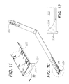
- FIG. 10 is a perspective view of a subsurface wound measuring device comprising another alternative embodiment of the present invention.
- FIG. 11 is a fragmentary, perspective view thereof, taken generally within circle 11 in FIG. 10 .
- FIG. 12 is a fragmentary, longitudinal cross-sectional view thereof, taken generally along line 12 - 12 in FIG. 11 .
- FIG. 13 is a fragmentary, perspective view of a subsurface wound measuring device comprising another alternative embodiment of the present invention.
- FIG. 13A is a fragmentary, perspective view of a subsurface wound measuring device, which can be fitted with various end configurations, as shown in cross-sectional FIGS. 14-16 taken generally along line 14 / 15 / 16 in FIG. 13A .
- FIG. 14 is a fragmentary, cross-sectional view taken generally along section line 14 in FIG. 13A and showing a modified aspect or embodiment of the subsurface wound measuring device of the present invention.
- FIG. 15 is a fragmentary, cross-sectional view taken generally along section line 15 in FIG. 13A and showing another modified aspect or embodiment of the subsurface wound measuring device of the present invention.
- FIG. 16 is a fragmentary, cross-sectional view taken generally along section line 16 in FIG. 13A and showing another modified aspect or embodiment of the subsurface wound measuring device of the present invention.
- FIG. 17 is a fragmentary, top plan view of another alternative wound measuring device, which is adapted for retrieving tissue and fluid samples.
- FIG. 18 is a fragmentary, side elevational view thereof, shown in a tissue or fluid sample gathering position within a wound, taken generally along line 18 in FIG. 17 .
- FIG. 19 is a fragmentary, cross-sectional view thereof, taken generally along line 19 in FIG. 17 .
- the reference numeral 2 generally designates a subsurface wound measuring device embodying the present invention. Without limitation on the generality of useful applications of the device 2 , as shown in FIG. 2 , it is particularly useful for obtaining linear dimensions corresponding to the size and configuration of an undermined subsurface wound cavity 4 , which includes an opening 5 at the skin layer 6 , a sidewall 7 with an inner portion 7 a adjacent to a wound base 8 an outer portion 7 b adjacent to the opening 5 .
- the sidewall inner portion 7 a is larger than the outer portion 7 b , whereby the wound cavity 4 undermines the patient's skin layer 6 .
- Such an undermined configuration presents difficulties in directly obtaining measurements since the sidewall inner portion 7 a is largely obscured.
- the wound cavity 4 can extend to the fascia layer and beyond.
- the measuring device 2 is adapted for taking multiple linear measurements of a wound, not only of the skin opening but also of the irregular configuration of the undermined portion, including lengths, widths and depths. Such measurements can be used to generate a model of the wound in two or three dimensions.
- the measuring device 2 generally includes a flexible, upwardly-concave strip 10 with first and second ends 12 , 14 .
- the first end 12 can be radiused as shown for patient comfort.
- the concavity of the strip 10 facilitates bending at an elbow 13 whereby first and second sections 20 a , 20 b are formed adjacent to the ends 12 , 14 respectively.
- the respective lengths of the sections 20 a , 20 b can vary along the length of the strip 10 , depending upon where the elbow 13 is formed.
- a tubular sleeve 16 is mounted on the strip 10 adjacent to its second end 14 , and includes a sleeve passage 17 .
- the sleeve 16 is adapted for grasping, e.g. with the thumb and forefinger, whereby the device 2 can be positioned, guided and manipulated within the wound cavity 4 .
- the strip 10 includes an upper surface 18 , which can be provided with measuring structure comprising a printed scale 19 corresponding to suitable linear values represented by indicia 21 , such as centimeters.
- the scale 19 can extend for the length of the strip 10 and can originate at the first end 12 .
- FIG. 2 shows the device 2 placed in the wound cavity 4 for measuring same according to the method of the present invention.
- An elbow 13 can be formed with the strip first section 20 a extending generally horizontally therefrom to a first point PI at its first end 12 on the cavity sidewall inner portion 7 a .
- a first distance L 1 from the elbow 13 to PI can be measured, observed and recorded.
- the depth D, as measured from point P 3 to P 4 can be determined with the measuring device 2 ( FIG. 2 ). It will be appreciated a number of measurements can be taken, as appropriate for the nature of the wound, the precision requirements for measuring same, etc.
- FIGS. 3A and 3B show the measuring device 2 being used to obtain measurements of the wound 4 in a different area thereof.
- the undermined, wound inner portion 7 a can extend in multiple directions from the wound opening 5 .
- a first length measurement is taken to determine L 1 in a first undermined area
- a second length measurement determines L 2 in a second undermined area
- the third length measurement L 3 is taken across the opening 5 .
- the overall length of the wound 4 is thus the sum of L 1 +L 2 +L 3 .
- the depth D of the wound 4 can also be determined as shown. Additional measurements can be taken as needed, for example to determine distances between various opposite points on the wound sidewall. Given the generally irregular configurations of wounds, which configurations change with healing, it will be appreciated that multiple dimensional values may be required in order to accurately model a wound in two or three dimensions and monitor its healing progress.
- FIG. 4 shows a measuring device 52 comprising an alternative embodiment of the present invention.
- the device 52 includes a removable tip 54 adapted for mounting on a strip 56 second end 58 to facilitate gripping, guiding, inserting and manipulating same.
- FIG. 5 shows another alternative embodiment measuring device 60 of the invention with a collar 62 including an arcuate slot 64 slidably receiving the strip 10 or the strip 56 and adapted for gripping to facilitate inserting, positioning and guiding the strip 10 or 56 .
- FIGS. 6A , 6 B and 7 show another alternative embodiment wound measuring device 102 , including a measuring strip 110 with first and second ends 112 , 114 associated with respective first and second sections 120 a , 120 b separated by an elbow 113 .
- the measuring strip 110 has an arcuate, upwardly-concave configuration with an upper surface 118 including a measuring structure comprising a scale 119 .
- the measuring strip 110 is adapted for use in conjunction with the measuring device 2 described above, which in this configuration provides a guide strip 10 for guiding and directing the measuring strip 110 into and within the wound cavity 4 . As shown in FIGS.
- the sleeve passage 17 telescopically and slidably receives the measuring strip 110 , which forms an elbow 113 adjacent to the elbow 13 whereby the measuring strip sections 120 a , 120 b partly overlie the respective guide strip sections 20 a , 20 b .
- the measuring strip 110 can thus be advanced into the wound cavity 4 and extended to engage its sidewalls 7 a , 7 b , with the guide strip 10 providing a layer of protection and between the measuring strip 110 and the patient, particularly along the wound base 8 .
- FIG. 7 shows the measuring strip 110 separated from the guide strip 10 . It will be appreciated that the guide and measuring strips 10 and 110 ( FIGS. 1 and 7 respectively) can be used together in the measuring device 102 configuration described above or independently.
- FIGS. 8 and 9 show the measuring strip 110 fitted with a movable sleeve 130 having a passage 132 , which telescopically and slidably receives the measuring strip 110 .
- the movable sleeve 130 is adapted for providing an index whereby a location along the length scale 119 can be marked for reference, e.g. when the measuring strip 110 is extracted.
- the strip 10 can also be fitted with the movable sleeve 130 for indexing particular locations along its length.
- the measuring strip 110 can be placed on the guide strip 10 of the measuring device 2 , and held digitally in place to mark a spot (e.g. the elbow 13 position) for a measurement, which can be readily read when the guide and measuring strips 10 , 110 are extracted together from the wound cavity 4 .
- a spot e.g. the elbow 13 position
- any relatively stiff, sterile available material such as a cotton-tipped applicator, can be used with the guide strip 10 to obtain a measurement.
- the sleeve 130 shown in FIGS. 8 and 9 can be freely movable and also require external fixation to hold and mark a position, or it can have an internal fixing and releasing device or spring.
- FIGS. 10-12 show an alternative embodiment measuring strip 222 , which includes a flat or blunt first end structure 224 , which is adapted for abutting a wound cavity surface.
- the blunt-ended configuration of the end structure 224 which presents a relatively flat engagement face 226 , reduces or eliminates penetration into tissue within wound cavities, whereby relatively accurate length measurements can be taken with minimal patient discomfort.
- the end structure 224 includes a fillet 228 , which flares into the upper surface of the measuring strip 222 .
- FIG. 13 shows another alternative embodiment measuring strip 232 , which includes an arcuate, upwardly-concave lip 234 forming a first end structure 236 with a generally tubular configuration adapted for minimizing patient discomfort and providing accurate readings.
- FIGS. 14-16 comprise fragmentary, cross-sectional views taken generally along line 14 / 15 / 16 in FIG. 13A , which shows a portion of alternative embodiment measuring strips 242 , 252 and 262 and the general location of end structures 246 , 256 and 266 in relation thereto.
- FIGS. 14-16 show the further alternative embodiment measuring strips 242 , 252 and 262 respectively with the end structures 246 , 256 and 266 including flanges 244 , 254 and 264 .
- the end structure 246 is integrally formed with the measuring strip 242 .
- the end structures 256 , 266 comprise separate clips attached to the measuring strips 252 , 262 with the flanges 254 , 264 depending downwardly and extending upwardly therefrom respectively.
- FIGS. 17-19 show another alternative embodiment biopsy/measuring device 302 comprising a measuring strip 310 with a first end 312 forming a distally-opened receptacle 330 adapted for receiving and extracting a tissue or fluid sample 332 , e.g. for culture purposes in connection with a biopsy.
- the device 302 can be used for sample collecting, measuring or both in one or more procedures. For example, in connection with measuring an undermined wound cavity, samples can be collected for analysis whereby treatment progress and potential pathogenic conditions can be monitored by analyzing the collected samples.
- guide and measuring strips can be provided for the guide and measuring strips, including disposable tips and absorbable materials for applying pharmaceuticals or taking fluid samples.
- guide and measuring strip end structures can be modified by medical practitioners as necessary to accommodate a wide range of wound cavities among patients having unique conditions and treatment procedures.
Landscapes
- Health & Medical Sciences (AREA)
- Life Sciences & Earth Sciences (AREA)
- Biomedical Technology (AREA)
- Molecular Biology (AREA)
- Veterinary Medicine (AREA)
- Biophysics (AREA)
- Pathology (AREA)
- Engineering & Computer Science (AREA)
- Public Health (AREA)
- Heart & Thoracic Surgery (AREA)
- Medical Informatics (AREA)
- Physics & Mathematics (AREA)
- Surgery (AREA)
- Animal Behavior & Ethology (AREA)
- General Health & Medical Sciences (AREA)
- Dentistry (AREA)
- Oral & Maxillofacial Surgery (AREA)
- Dermatology (AREA)
- Measurement Of The Respiration, Hearing Ability, Form, And Blood Characteristics Of Living Organisms (AREA)
Abstract
Description
Claims (6)
Priority Applications (2)
| Application Number | Priority Date | Filing Date | Title |
|---|---|---|---|
| US12/658,836 US8568337B2 (en) | 2005-05-13 | 2010-02-16 | Medical measuring device and method |
| US29/432,154 USD694883S1 (en) | 2005-05-13 | 2012-09-13 | Medical wound measuring device |
Applications Claiming Priority (2)
| Application Number | Priority Date | Filing Date | Title |
|---|---|---|---|
| US11/129,614 US7662112B2 (en) | 2005-05-13 | 2005-05-13 | Medical measuring device and method |
| US12/658,836 US8568337B2 (en) | 2005-05-13 | 2010-02-16 | Medical measuring device and method |
Related Parent Applications (1)
| Application Number | Title | Priority Date | Filing Date |
|---|---|---|---|
| US11/129,614 Continuation US7662112B2 (en) | 2005-05-13 | 2005-05-13 | Medical measuring device and method |
Related Child Applications (1)
| Application Number | Title | Priority Date | Filing Date |
|---|---|---|---|
| US29/432,154 Continuation USD694883S1 (en) | 2005-05-13 | 2012-09-13 | Medical wound measuring device |
Publications (2)
| Publication Number | Publication Date |
|---|---|
| US20100152618A1 US20100152618A1 (en) | 2010-06-17 |
| US8568337B2 true US8568337B2 (en) | 2013-10-29 |
Family
ID=37420093
Family Applications (3)
| Application Number | Title | Priority Date | Filing Date |
|---|---|---|---|
| US11/129,614 Active 2026-06-26 US7662112B2 (en) | 2005-05-13 | 2005-05-13 | Medical measuring device and method |
| US12/658,836 Active 2027-04-23 US8568337B2 (en) | 2005-05-13 | 2010-02-16 | Medical measuring device and method |
| US29/432,154 Active USD694883S1 (en) | 2005-05-13 | 2012-09-13 | Medical wound measuring device |
Family Applications Before (1)
| Application Number | Title | Priority Date | Filing Date |
|---|---|---|---|
| US11/129,614 Active 2026-06-26 US7662112B2 (en) | 2005-05-13 | 2005-05-13 | Medical measuring device and method |
Family Applications After (1)
| Application Number | Title | Priority Date | Filing Date |
|---|---|---|---|
| US29/432,154 Active USD694883S1 (en) | 2005-05-13 | 2012-09-13 | Medical wound measuring device |
Country Status (1)
| Country | Link |
|---|---|
| US (3) | US7662112B2 (en) |
Families Citing this family (19)
| Publication number | Priority date | Publication date | Assignee | Title |
|---|---|---|---|---|
| TWI266217B (en) * | 2004-12-28 | 2006-11-11 | Ind Tech Res Inst | Methods and devices of a multi-functional operating interface for a nursing machine |
| US7662112B2 (en) * | 2005-05-13 | 2010-02-16 | Kci Licensing, Inc. | Medical measuring device and method |
| US7401413B1 (en) * | 2007-02-20 | 2008-07-22 | Chris L Nelson | Disposable wound measuring device |
| US20090005786A1 (en) * | 2007-06-28 | 2009-01-01 | Stryker Trauma Gmbh | Bone hole measuring device |
| AU2008310622B2 (en) * | 2007-10-11 | 2014-01-09 | Solventum Intellectual Properties Company | Closed incision negative pressure wound therapy device and methods of use |
| US8444614B2 (en) * | 2009-04-10 | 2013-05-21 | Spiracur, Inc. | Methods and devices for applying closed incision negative pressure wound therapy |
| EP2416816B1 (en) * | 2009-04-10 | 2014-10-15 | Spiracur Inc. | Methods and devices for applying closed incision negative pressure wound therapy |
| US9339365B2 (en) * | 2011-07-07 | 2016-05-17 | David D. Park | Device and method for delivering grafts |
| USD750776S1 (en) * | 2014-02-27 | 2016-03-01 | Andrew B. Lytle | Surgical alignment device |
| USD799696S1 (en) * | 2015-06-18 | 2017-10-10 | Edward Via Virginia College Of Osteopathic Medicine | Human lumbar puncture assist device |
| USD810286S1 (en) * | 2016-04-28 | 2018-02-13 | Gyrus Acmi, Inc. | Suction canister mounting bracket |
| EP3648677B1 (en) | 2017-07-06 | 2025-02-26 | Park Surgical Innovations, Llc | Device for delivering grafts at a surgical site |
| US11090145B2 (en) | 2017-07-06 | 2021-08-17 | Park Surgical Innovations, Llc | Device for delivering grafts at a surgical site and method |
| USD894384S1 (en) * | 2018-01-29 | 2020-08-25 | Transit Scientific, LLC | Elongated medical device with flexibility enhancing features |
| CN108836341B (en) * | 2018-07-26 | 2024-03-19 | 北京医院 | spinal stereotaxic ruler |
| JP7309556B2 (en) * | 2019-09-26 | 2023-07-18 | キヤノン株式会社 | Image processing system and its control method |
| CN110680330B (en) * | 2019-10-31 | 2022-04-19 | 中国人民解放军陆军军医大学第一附属医院 | Wound Measurement and Assessment Tools |
| TWD209335S (en) | 2020-03-31 | 2021-01-11 | 長庚學校財團法人長庚科技大學 | Wound measurer |
| US20240115388A1 (en) * | 2022-10-10 | 2024-04-11 | Atricure, Inc. | Devices and methods for determining clip size for left atrial appendage occlusion |
Citations (9)
| Publication number | Priority date | Publication date | Assignee | Title |
|---|---|---|---|---|
| US5807280A (en) | 1997-02-25 | 1998-09-15 | Linda Sue Mangels | Pressure ulcer measurement probe and method |
| US5860923A (en) | 1995-01-30 | 1999-01-19 | Cardiovascular Concepts, Inc. | Lesion measurement catheter and method |
| US6159167A (en) | 1999-04-12 | 2000-12-12 | Hardin-Naser; Juel E. | Disposable wound measuring device and method |
| USD440659S1 (en) | 1999-04-16 | 2001-04-17 | Asahi Kogaku Kogyo Kabushiki Kaisha | Endoscope |
| US6381488B1 (en) | 1999-06-15 | 2002-04-30 | Sandia Corporation | Method and apparatus to measure the depth of skin burns |
| US6413212B1 (en) | 1996-10-17 | 2002-07-02 | Faro Technologies, Inc. | Method and apparatus for wound management |
| US6454720B1 (en) | 1998-05-18 | 2002-09-24 | Commissariat A L'energie Atomique | System for measuring physical parameters with a medical probe |
| US6640460B1 (en) | 1999-10-18 | 2003-11-04 | T-Bra Limited | Measuring device and method |
| JP2004073769A (en) | 2002-08-09 | 2004-03-11 | Masaaki Kosaka | Decubitus pocket measure |
Family Cites Families (21)
| Publication number | Priority date | Publication date | Assignee | Title |
|---|---|---|---|---|
| US1491444A (en) * | 1921-03-24 | 1924-04-22 | Louis E Dornseifer | Ring gauge |
| USD260974S (en) * | 1979-10-25 | 1981-09-29 | Lesser N Lewis | Sampling depth bob |
| USD264824S (en) * | 1979-11-30 | 1982-06-08 | Dan Sandel | Combined surgical ruler and marking pen |
| USD271821S (en) * | 1981-06-15 | 1983-12-20 | Kelson Shirley J P | Sewing aid |
| USD276897S (en) * | 1982-09-07 | 1984-12-25 | Woods Stephanie C | Telescoping measuring stick |
| USD312306S (en) * | 1987-11-16 | 1990-11-20 | Michelson Gary K | Suction retractor |
| US5660923A (en) * | 1994-10-31 | 1997-08-26 | Board Of Trustees Operating Michigan State University | Method for the preparation of metal matrix fiber composites |
| US6494848B1 (en) * | 1996-12-19 | 2002-12-17 | St. Jude Medical Puerto Rico B.V. | Measuring device for use with a hemostatic puncture closure device |
| USD415274S (en) * | 1998-04-17 | 1999-10-12 | Koros Tibor B | Adjustable length retractor/distractor blade |
| USD430668S (en) * | 1999-07-02 | 2000-09-05 | Koros Tibor B | Adjustable length retractor/distractor blade |
| USD455972S1 (en) * | 2000-09-06 | 2002-04-23 | Michael D. Gilbert | Refill reminder insert for prescription medicine bottle |
| USD448687S1 (en) * | 2000-12-06 | 2001-10-02 | Gator Grip, Inc. | Fish measuring device |
| USD506398S1 (en) * | 2004-02-09 | 2005-06-21 | Harry L. Bunkowfst | Fish measuring device |
| US7662112B2 (en) * | 2005-05-13 | 2010-02-16 | Kci Licensing, Inc. | Medical measuring device and method |
| USD574494S1 (en) * | 2006-02-22 | 2008-08-05 | Schmitt Lydia P | Tongue depressor |
| USD629897S1 (en) * | 2007-01-23 | 2010-12-28 | Tibor Koros | Tapered retractor blade |
| USD616316S1 (en) * | 2009-06-12 | 2010-05-25 | Tim Mangan | Laser assistant |
| USD682425S1 (en) * | 2010-02-10 | 2013-05-14 | Unique Surgical Innovations, Llc | Airway evaluator for orotracheal intubation |
| US20120259230A1 (en) * | 2011-04-11 | 2012-10-11 | Elven Riley | Tool for recording patient wound history |
| USD658287S1 (en) * | 2011-07-29 | 2012-04-24 | Greatbatch Ltd. | Inferior acetabular/piriformis retractor |
| USD685087S1 (en) * | 2012-03-05 | 2013-06-25 | Misonix Incorporated | Surgical instrument sleeve |
-
2005
- 2005-05-13 US US11/129,614 patent/US7662112B2/en active Active
-
2010
- 2010-02-16 US US12/658,836 patent/US8568337B2/en active Active
-
2012
- 2012-09-13 US US29/432,154 patent/USD694883S1/en active Active
Patent Citations (9)
| Publication number | Priority date | Publication date | Assignee | Title |
|---|---|---|---|---|
| US5860923A (en) | 1995-01-30 | 1999-01-19 | Cardiovascular Concepts, Inc. | Lesion measurement catheter and method |
| US6413212B1 (en) | 1996-10-17 | 2002-07-02 | Faro Technologies, Inc. | Method and apparatus for wound management |
| US5807280A (en) | 1997-02-25 | 1998-09-15 | Linda Sue Mangels | Pressure ulcer measurement probe and method |
| US6454720B1 (en) | 1998-05-18 | 2002-09-24 | Commissariat A L'energie Atomique | System for measuring physical parameters with a medical probe |
| US6159167A (en) | 1999-04-12 | 2000-12-12 | Hardin-Naser; Juel E. | Disposable wound measuring device and method |
| USD440659S1 (en) | 1999-04-16 | 2001-04-17 | Asahi Kogaku Kogyo Kabushiki Kaisha | Endoscope |
| US6381488B1 (en) | 1999-06-15 | 2002-04-30 | Sandia Corporation | Method and apparatus to measure the depth of skin burns |
| US6640460B1 (en) | 1999-10-18 | 2003-11-04 | T-Bra Limited | Measuring device and method |
| JP2004073769A (en) | 2002-08-09 | 2004-03-11 | Masaaki Kosaka | Decubitus pocket measure |
Non-Patent Citations (2)
| Title |
|---|
| Kosaka, M.D., et al., "Pocket Measure: An Exclusive Tool for Measuring and Recording Pressure Ulcer Pockets"; Plastic and Reconstructive Surgery, (Aug. 2004), vol. 114, No. 2, pp. 624-625; American Society of Plastic Surgeons. |
| US Marketing Services Worldwide Web Site (www.usmsinc.com); advertising for the "Wound Stick Measuring Stick", "Wound Stick Tunneler" and "Wound Map" products. |
Also Published As
| Publication number | Publication date |
|---|---|
| US20060258961A1 (en) | 2006-11-16 |
| US20100152618A1 (en) | 2010-06-17 |
| USD694883S1 (en) | 2013-12-03 |
| US7662112B2 (en) | 2010-02-16 |
Similar Documents
| Publication | Publication Date | Title |
|---|---|---|
| US8568337B2 (en) | Medical measuring device and method | |
| JP7324322B2 (en) | Flexible biopsy needle system | |
| US12096996B2 (en) | Systems and methods of registration for image-guided procedures | |
| JP6703590B2 (en) | Needle guidance system for use with ultrasonic devices | |
| CN114366181B (en) | Telescopic biopsy needle | |
| CN107184272B (en) | Composite curve type navigation catheter | |
| CN204636425U (en) | Systems and biopsy tools for performing surgical procedures | |
| Ahn et al. | Robotic palpation and mechanical property characterization for abnormal tissue localization | |
| CN105473098A (en) | Systems and methods for medical procedure confirmation | |
| US20250049423A1 (en) | Biopsy tool | |
| JP3093260B2 (en) | Medical instruments and handle | |
| JP7281837B2 (en) | Surgical sounding instrument | |
| US4997368A (en) | Oral measuring device | |
| US10743959B2 (en) | Device and methods of needle calibration | |
| CN216221413U (en) | OCT detects nasopharynx guide and includes its biopsy device | |
| RU56795U1 (en) | TOOL FOR COLLECTING MATERIAL FROM THE MOSCOW OF THE NOSE CAVITY | |
| CN210990303U (en) | Clinical examination gloves that possess measurement function | |
| JPH074001Y2 (en) | Insertion depth measuring instrument for endoscope insertion part | |
| CN113520330A (en) | OCT detects nasopharynx guide and includes its biopsy device | |
| EP2233110A1 (en) | Methods and apparatus to determine distances for use in dentistry | |
| JPS5930422B2 (en) | biological tissue collector | |
| ITMI940634A1 (en) | EQUIPMENT FOR MEASURING THE LENGTH OF ANATOMICAL SEGMENTS BY MEANS OF ECHOGRAPHY. |
Legal Events
| Date | Code | Title | Description |
|---|---|---|---|
| AS | Assignment |
Owner name: ZAMPAT, L.L.C., KANSAS Free format text: ASSIGNMENT OF ASSIGNORS INTEREST;ASSIGNOR:ZAMIEROWSKI, DAVID S., M.D.;REEL/FRAME:025233/0980 Effective date: 20060316 |
|
| AS | Assignment |
Owner name: KCI LICENSING, INC., TEXAS Free format text: ASSIGNMENT OF ASSIGNORS INTEREST;ASSIGNOR:ZAMPAT, L.L.C.;REEL/FRAME:025239/0135 Effective date: 20060316 |
|
| STCF | Information on status: patent grant |
Free format text: PATENTED CASE |
|
| FPAY | Fee payment |
Year of fee payment: 4 |
|
| MAFP | Maintenance fee payment |
Free format text: PAYMENT OF MAINTENANCE FEE, 8TH YEAR, LARGE ENTITY (ORIGINAL EVENT CODE: M1552); ENTITY STATUS OF PATENT OWNER: LARGE ENTITY Year of fee payment: 8 |
|
| AS | Assignment |
Owner name: 3M INNOVATIVE PROPERTIES COMPANY, MINNESOTA Free format text: ASSIGNMENT OF ASSIGNORS INTEREST;ASSIGNOR:KCI LICENSING, INC.;REEL/FRAME:065769/0375 Effective date: 20221205 |
|
| AS | Assignment |
Owner name: SOLVENTUM INTELLECTUAL PROPERTIES COMPANY, MINNESOTA Free format text: ASSIGNMENT OF ASSIGNORS INTEREST;ASSIGNOR:3M INNOVATIVE PROPERTIES COMPANY;REEL/FRAME:066333/0137 Effective date: 20240201 |
|
| MAFP | Maintenance fee payment |
Free format text: PAYMENT OF MAINTENANCE FEE, 12TH YEAR, LARGE ENTITY (ORIGINAL EVENT CODE: M1553); ENTITY STATUS OF PATENT OWNER: LARGE ENTITY Year of fee payment: 12 |