US856494A - Pneumatic-tire clip. - Google Patents
Pneumatic-tire clip. Download PDFInfo
- Publication number
- US856494A US856494A US29483306A US1906294833A US856494A US 856494 A US856494 A US 856494A US 29483306 A US29483306 A US 29483306A US 1906294833 A US1906294833 A US 1906294833A US 856494 A US856494 A US 856494A
- Authority
- US
- United States
- Prior art keywords
- band
- tire
- clip
- rim
- edges
- Prior art date
- Legal status (The legal status is an assumption and is not a legal conclusion. Google has not performed a legal analysis and makes no representation as to the accuracy of the status listed.)
- Expired - Lifetime
Links
Images
Classifications
-
- B—PERFORMING OPERATIONS; TRANSPORTING
- B60—VEHICLES IN GENERAL
- B60C—VEHICLE TYRES; TYRE INFLATION; TYRE CHANGING; CONNECTING VALVES TO INFLATABLE ELASTIC BODIES IN GENERAL; DEVICES OR ARRANGEMENTS RELATED TO TYRES
- B60C15/00—Tyre beads, e.g. ply turn-up or overlap
- B60C15/02—Seating or securing beads on rims
- B60C15/028—Spacers between beads
Definitions
- This ehp' comprises a -shaft or bolt a a ted to pass through the rim and felly, an is rovided with a nut or cap, usually 'threa ed, by means of ⁇ which the shaft can be pulled downward.
- The'upper extremity of the clip terminates in a device which consists of a comparatively flat central portion and two upwardly extending flanges at its opposite sides which are inclined outward. These flanges are spaced and shaped to fit against the similarly inclined portlons of the inner surface of-,the tire-easing, 4and will, when pulled downward, act as a wedge between theltoes of the tire beads,l force the said beads firmly into the clenches, and
- the Object of my invention is to provide a single structure which shall actas a clip about the entire periphery of the wheel, and which can be applied by a single operation. I accomplish these objects by means of the structure hereinafter described and claimed, reference being had to the drawings which form a part thereof.
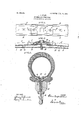
- Fig. 1, 1 is the base plate of the continuous clip, and comprises an annular band or strip, preferably of metal, which is adapted to extend about substantially the entire periphery of the wheel.
- the edges of this band are provided with upwardly extending flanges 2 and 3, which are inclined outwardly and sha ed to seat against the toes of the tire bea s. of the flanges at its edges is such thatwhen the band is drawn tightly about the rim it will act as a Wedge between the inclined ilmer surfaces of the tire-casing and force the beads firmly into the clenches.
- I provide it with some form of sliding or telescop joint, which will permit the ends of the band The formation of this band and Y to be drawn together or forced apart 'at will.
- a binding plate 4 which has a general form similar to that of the main band, having a base plate and edge flanges, although its Width is slightly 'less than that of the main band to permit the former to slide within the latter.
- Near the ends of this plate I provide downwardly extending screws or rivets fand 6, which are solidly attached to the binding plate and which extend downwardly through elongated slots 7 and 8 in the adjoining ends of the clip.
- valve-Stem or bolt there must be a head of too great diameter to pass through the slot 9, and I prefer to provide a nut l() having beveled and flattened sides, which will permit this nut to seat within' the slot, and if the nut is made integral with the bridge washer 11 the valve stem is held from rotation.
- a nut l() having beveled and flattened sides, which will permit this nut to seat within' the slot, and if the nut is made integral with the bridge washer 11 the valve stem is held from rotation.
- the compression means which consists of the triangular lugs 12 and 13, one upon the under side of the band near each terminal, and the slots 14 and 15 cut in the rim and suitably located to co-operate with the lugs.
- the operation of my device' is as follows: The clip is distendedsufliciently to allow it to be slipped over o ne clench and placed about the channel-iron between the clenches,
- the hole 9 registerin with the hole 'in the channel-ironand fel y. designed to receive ⁇ the valve or the bolt which may be used in its place.
- the tire is then applied, its beads being seated within the clenches and the valvestem thrust through the binding plate, channeliron and felly.
- the tire is milated and the downward pressure thus 'eXertedu on the cli causes the inclined faces of the ugs 12 an ⁇ 13 to contact witllthe Islot edges and thusl compresses the band against the tire casing, forcing the beads firmly' into the clenches.
- the cap 16 or any suitable form of nut which may be substituted therefor is then attached to the. valve stem and tightdownwardly upon this partof ⁇ position, ⁇ partially atleast, before applying the cap.-
- degree o expansion and contraction oi which the clip is capable can be varied to adapt the structure to the forml of the rim intended to be -used.
- the proportions must be such. however that the band can be expanded sul"- ficiently to slip over the rim vHangin and contracted enough to seat tightly between the casing edges.
- My device is particularly adapted for use with wheel rims having a removable ilange in whichcase the degree of expansion and contraction needed is very slight.
- a clip for pneumatic tire casings comprising an annular split band adapted to be contracted circumferentially by the inflation of said casing and means for electing such contraction integral with said band, adapted to co-act with means integral with the tire seating channel.
- a retaining clip for pneumatic tire casings comprising an annular compression band and contracting means integral with said band adapted to co-act with means integral IOO ation of the tire.
- a clip for neumatic tire casings comprising a leXib e annular band and means for engagement between the band and the rim for contracting the said band -when downward pressure is exerted upon it.
- a retaining clip for tire casings comprising an annular compression band and coacting meansintegral respectively with. the band and the wheel rimior contracting the band when the tire is inflated, and means for securing the band in the contracted position; 5.
- a clip for eleneher tire casings eomprising an annular band, a binding plate slidably i connected to the terminals of said band, and ni aus formed upon said band for causing its terminals to approach each other when the binding plate is forced downward, substanl tially as described.
- a retaining band for tire casings comprising a flexible annular plate adapted to lie between the easing edges, upwardly and outwardly projecting [langes upon the edges of said plate adapted to contact with the inner surfaces ol the easing edges, a binding plate slidably ('.onneeted to the terminals of said plate, wedges extending dowmvardly Afrom said plate, slots in the wheel rim adapted to engage said wedges and to force the plate terminals toward each otherwhen the plate is forced downward, and means for forcing said plate downward toward the channel-iron, substantially as described.
- a continuous clip fortire casings compris'ing an annular compression band adapt ed to lie between the edges of a tire casing, outwardly and upwardly projecting flanges with a nut seating against the upper surface of said plate, and a threadedeap adapted to draw said stem and Said binding plate downl ward.
- a continuons clip for pneumatic tire easings comprising the flexibleband 1, the flanges 2 and 3 upon its edges, the binding plate. 4 slidably eonneeled lo the terminals of said band, the triangular ⁇ 'edges 12 and 13 extending downwardly l'roin said band, the slots 14 and l5 in the channel-iron adapted to reeeivo said wedges, the valve-stem 1S earrying the nut l() adapted to seat within the. slot S) in said binding plate. and the cap 1G adapted to engage the extremity of the valve-stem and to draw said stem and said v binding plate do ⁇ 'nward.
Landscapes
- Engineering & Computer Science (AREA)
- Mechanical Engineering (AREA)
- Check Valves (AREA)
- Tires In General (AREA)
Description
PATENTED JUNE 11, 1907. E. G. SHAW. PNEUMATIG TIRE CLIP.
APPLIUATION FILED JAN.6.1906.
a /ll WITNESSES ATTORNEY tion to a certain extent.
,ferentially about the rim.
' UNITED STATES PATENT OFFICE.
EDWIN OOUPLAND SHAW, oF AKRON, OHIO, As'sIeNoR To THF B. F. GOODRIOII COMPANY, oF AKRON, OHIO, A CORPORATION OF OHIO.
PNsuMAi-lc-Tme cLlP.
Specification of Letters Patent.
Patented June 11, 1907.
Application filed January,6,1906. Serial No. 294,833.
' of the clincher tire resides in the form of that part of the tire-casing which adj oins and is secured to the wheel rim. The edges of the tire-casing terminate in beads formed thereon, which are shaped to be grasped and held by outwardly, upwardly and inwardly curved lianges extending along the edges of the Wheel rim. The beads and flanges are so shaped that any pressure from within the casing tends to seat the beads more firmly in the clinehes, the inflation of the tirev in the case of pneumatictires performing this func- -This pressure, however, is not sufficient to insure the attachment 'of the tire to the rim particularly in the event of severe lateral strains, nor to prevent creeping or movement of the tire circum- I Moreover, should the tire become deflated, even this degree of security is 10st and the tire easily becomes detached. In the present state of the art certain devices are in use adapted to increase the security of this attachment. These devices, which are termed clips, are provided inside the tire-casing at varlous points along its len th. This ehp' comprises a -shaft or bolt a a ted to pass through the rim and felly, an is rovided with a nut or cap, usually 'threa ed, by means of `which the shaft can be pulled downward. The'upper extremity of the clip terminates in a device which consists of a comparatively flat central portion and two upwardly extending flanges at its opposite sides which are inclined outward. These flanges are spaced and shaped to fit against the similarly inclined portlons of the inner surface of-,the tire-easing, 4and will, when pulled downward, act as a wedge between theltoes of the tire beads,l force the said beads firmly into the clenches, and
securey them therein, irrespective of the air pressure inside .the inner tube. lWith the usual automobile tire from four to six ef these clips are used, and the labor of adjustin them and of adjusting the tire casing an( inner tube with relation thereto is considerable.
The Object of my invention is to provide a single structure which shall actas a clip about the entire periphery of the wheel, and which can be applied by a single operation. I accomplish these objects by means of the structure hereinafter described and claimed, reference being had to the drawings which form a part thereof.
Throughout the drawings like reference numerals refer to like parts.
In Fig. 1, 1 is the base plate of the continuous clip, and comprises an annular band or strip, preferably of metal, which is adapted to extend about substantially the entire periphery of the wheel. The edges of this band are provided with upwardly extending flanges 2 and 3, which are inclined outwardly and sha ed to seat against the toes of the tire bea s. of the flanges at its edges is such thatwhen the band is drawn tightly about the rim it will act as a Wedge between the inclined ilmer surfaces of the tire-casing and force the beads firmly into the clenches. To permit the clip to `be contracted or distended, I provide it with some form of sliding or telescop joint, which will permit the ends of the band The formation of this band and Y to be drawn together or forced apart 'at will.
I have shown in the drawings, Figs. 1 and 2,
an operative form of such a joint, although other methods of uniting the clip ends will readily suggest themselves. I provide a binding plate 4 which has a general form similar to that of the main band, having a base plate and edge flanges, although its Width is slightly 'less than that of the main band to permit the former to slide within the latter. Near the ends of this plate I provide downwardly extending screws or rivets fand 6, which are solidly attached to the binding plate and which extend downwardly through elongated slots 7 and 8 in the adjoining ends of the clip. The lower ends of these screws or rivets are provided With nuts or are headed to retain the shafts within the' slots, while the' connection is sulicientl'y loose to permit longitudinal movementof the rivets in the slots, and consequently longitudinal movement of the bandends relatively to the binding plate. These rivets may be made removable or may be permanently inserted in position. rIhe resulting structure, then, is a continuous annular band or clip extending entirely about the rim, and which is capable ofexpansion and contraction. At the center of the binding plate I provide a slot 9 shaped to admit the valve-stem or some suitable form of bolt. Upon this valve-Stem or bolt there must be a head of too great diameter to pass through the slot 9, and I prefer to providea nut l() having beveled and flattened sides, which will permit this nut to seat within' the slot, and if the nut is made integral with the bridge washer 11 the valve stem is held from rotation. A u
Upon theunder side of the band near its terminals VI provide means for causing the.
terminals to approach each other when the band or the binding plate is forced downward toward the rim. I have shown one embodiment of the compression means which consists of the triangular lugs 12 and 13, one upon the under side of the band near each terminal, and the slots 14 and 15 cut in the rim and suitably located to co-operate with the lugs. The inclined faces of these lugs 'are placed posteriorly with relation to the binding plate-and are adapted to contact with the ed es ofthe slots so that any pressure exerte the band or upon the binding plate will draw the band terminals toward each other,
tighten the clip and thus force its flanges against the toes of the tire bead.
The operation of my device' is as follows: The clip is distendedsufliciently to allow it to be slipped over o ne clench and placed about the channel-iron between the clenches,
the hole 9 registerin with the hole 'in the channel-ironand fel y. designed to receive` the valve or the bolt which may be used in its place. The tire is then applied, its beads being seated within the clenches and the valvestem thrust through the binding plate, channeliron and felly. The tire is milated and the downward pressure thus 'eXertedu on the cli causes the inclined faces of the ugs 12 an` 13 to contact witllthe Islot edges and thusl compresses the band against the tire casing, forcing the beads firmly' into the clenches. The cap 16 or any suitable form of nut which may be substituted therefor is then attached to the. valve stem and tightdownwardly upon this partof` position,` partially atleast, before applying the cap.-
B ,varying the proportion of the band, bin( ing late, slots and triangular lugs, the
degree o expansion and contraction oi which the clip is capable can be varied to adapt the structure to the forml of the rim intended to be -used. The proportions must be such. however that the band can be expanded sul"- ficiently to slip over the rim vHangin and contracted enough to seat tightly between the casing edges. My device is particularly adapted for use with wheel rims having a removable ilange in whichcase the degree of expansion and contraction needed is very slight.-
Having described my invention what I claim is: if
1. A clip for pneumatic tire casings comprising an annular split band adapted to be contracted circumferentially by the inflation of said casing and means for electing such contraction integral with said band, adapted to co-act with means integral with the tire seating channel.
2. A retaining clip for pneumatic tire casings comprising an annular compression band and contracting means integral with said band adapted to co-act with means integral IOO ation of the tire.
.3. A clip for neumatic tire casings comprising a leXib e annular band and means for engagement between the band and the rim for contracting the said band -when downward pressure is exerted upon it.
- 6. In combination With'a tirecasing, a retaining clipcompri'sing'an annular compresi co-acting contracting means upon the band and rim respectively, .and Vintegral therewith,
adapted to drawsaid band-downwardly between the tireeiigsingwallaand means for securing the said band in the contracted position. Y 7. A clip for eleneher tire casings eomprising an annular band, a binding plate slidably i connected to the terminals of said band, and ni aus formed upon said band for causing its terminals to approach each other when the binding plate is forced downward, substanl tially as described.
S. A retaining band for tire casings comprising a flexible annular plate adapted to lie between the easing edges, upwardly and outwardly projecting [langes upon the edges of said plate adapted to contact with the inner surfaces ol the easing edges, a binding plate slidably ('.onneeted to the terminals of said plate, wedges extending dowmvardly Afrom said plate, slots in the wheel rim adapted to engage said wedges and to force the plate terminals toward each otherwhen the plate is forced downward, and means for forcing said plate downward toward the channel-iron, substantially as described.
9. A continuous clip fortire casings compris'ing an annular compression band adapt ed to lie between the edges of a tire casing, outwardly and upwardly projecting flanges with a nut seating against the upper surface of said plate, and a threadedeap adapted to draw said stem and Said binding plate downl ward.
10. A continuons clip for pneumatic tire easings comprising the flexibleband 1, the flanges 2 and 3 upon its edges, the binding plate. 4 slidably eonneeled lo the terminals of said band, the triangular \\' edges 12 and 13 extending downwardly l'roin said band, the slots 14 and l5 in the channel-iron adapted to reeeivo said wedges, the valve-stem 1S earrying the nut l() adapted to seat within the. slot S) in said binding plate. and the cap 1G adapted to engage the extremity of the valve-stem and to draw said stem and said v binding plate do\\\'nward. I
EDWIN COUPLAND SHAV.
'itnesses:
C. (l. Goonmen, W'. K. MEANS.
Priority Applications (1)
| Application Number | Priority Date | Filing Date | Title |
|---|---|---|---|
| US29483306A US856494A (en) | 1906-01-06 | 1906-01-06 | Pneumatic-tire clip. |
Applications Claiming Priority (1)
| Application Number | Priority Date | Filing Date | Title |
|---|---|---|---|
| US29483306A US856494A (en) | 1906-01-06 | 1906-01-06 | Pneumatic-tire clip. |
Publications (1)
| Publication Number | Publication Date |
|---|---|
| US856494A true US856494A (en) | 1907-06-11 |
Family
ID=2924949
Family Applications (1)
| Application Number | Title | Priority Date | Filing Date |
|---|---|---|---|
| US29483306A Expired - Lifetime US856494A (en) | 1906-01-06 | 1906-01-06 | Pneumatic-tire clip. |
Country Status (1)
| Country | Link |
|---|---|
| US (1) | US856494A (en) |
-
1906
- 1906-01-06 US US29483306A patent/US856494A/en not_active Expired - Lifetime
Similar Documents
| Publication | Publication Date | Title |
|---|---|---|
| US2410209A (en) | Combined wheel rim and pneumatic | |
| US856494A (en) | Pneumatic-tire clip. | |
| US779730A (en) | Vehicle-tire. | |
| US2308904A (en) | Antiskidding device | |
| US1348522A (en) | Spring-tire | |
| US2367820A (en) | Pneumatic tire and rim assembly | |
| US1336452A (en) | Tire | |
| US1140370A (en) | Vehicle-tire. | |
| US521482A (en) | smallman | |
| US921174A (en) | Pneumatic tire. | |
| US779731A (en) | Vehicle-tire. | |
| US697621A (en) | Pneumatic vehicle-tire. | |
| US707538A (en) | Rim and felly for rubber vehicle-tires. | |
| US1096467A (en) | Wheel-tire. | |
| US1330756A (en) | Tire | |
| US2014811A (en) | Vehicle wheel | |
| US886835A (en) | Means for attaching pneumatic tires. | |
| US587656A (en) | Bicycle-tire | |
| US894293A (en) | Vehicle-wheel rim. | |
| US1285419A (en) | Vehicle-tire. | |
| US1791596A (en) | Rim | |
| US3247879A (en) | Extensible tubeless tire bead and adjacent sidewall annulus | |
| US804896A (en) | Vehicle tire and rim. | |
| US2681680A (en) | Nonskid tire | |
| US680486A (en) | Detachable tire. |