US779730A - Vehicle-tire. - Google Patents
Vehicle-tire. Download PDFInfo
- Publication number
- US779730A US779730A US21025204A US1904210252A US779730A US 779730 A US779730 A US 779730A US 21025204 A US21025204 A US 21025204A US 1904210252 A US1904210252 A US 1904210252A US 779730 A US779730 A US 779730A
- Authority
- US
- United States
- Prior art keywords
- tire
- rim
- base
- inwardly
- bases
- Prior art date
- Legal status (The legal status is an assumption and is not a legal conclusion. Google has not performed a legal analysis and makes no representation as to the accuracy of the status listed.)
- Expired - Lifetime
Links
- 238000010276 construction Methods 0.000 description 4
- 239000000463 material Substances 0.000 description 3
- 230000008901 benefit Effects 0.000 description 2
- 230000004048 modification Effects 0.000 description 2
- 238000012986 modification Methods 0.000 description 2
- 208000027418 Wounds and injury Diseases 0.000 description 1
- 230000004308 accommodation Effects 0.000 description 1
- 230000009471 action Effects 0.000 description 1
- 230000006378 damage Effects 0.000 description 1
- 208000014674 injury Diseases 0.000 description 1
- 230000002452 interceptive effect Effects 0.000 description 1
- 238000004519 manufacturing process Methods 0.000 description 1
- 239000002184 metal Substances 0.000 description 1
- 238000000034 method Methods 0.000 description 1
- 230000002093 peripheral effect Effects 0.000 description 1
- 230000008569 process Effects 0.000 description 1
- 239000000126 substance Substances 0.000 description 1
Images


Classifications
-
- B—PERFORMING OPERATIONS; TRANSPORTING
- B60—VEHICLES IN GENERAL
- B60B—VEHICLE WHEELS; CASTORS; AXLES FOR WHEELS OR CASTORS; INCREASING WHEEL ADHESION
- B60B25/00—Rims built-up of several main parts ; Locking means for the rim parts
- B60B25/04—Rims with dismountable flange rings, seat rings, or lock rings
- B60B25/14—Locking means for flange rings or seat rings
- B60B25/20—Arrangement of screws, bolts, or shouldered pins
Definitions
- My invention relates to pneumatic tires for vehicles, and has reference more particularly to the heavy tires employed on the wheels of automobiles and motor-vehicles generally.
- the principal object of the invention is to provide an improved means for securing the tire upon the rim which shall combine simplicity of construction with strength and efficiency in operation and at the same time render the matter of applying andremoving the tire a simple and easily-performed operation.
- Another object of my invention is to provide an improved means for preventing creeping of the tire on the rim when partially or wholly deflated to prevent injury to the valvestem and inner tube.
- a leading feature of my invention consists of a tire and its seating and fastening means having as the chief novel and distinguishing characteristics a broad transversely-fiat rim in association with side flanges removably secured to one or both edges thereof and having wedgeshaped bases which point inwardly of the rim, presenting oppositely-inclined outer surfaces to seat the tire, in combination with a longitudinally-split hollow tire-body having its inner peripheral portion or base formed to seat upon the wedgeshaped bases of the flanges and under the internal pressure of the contained air be expanded into a close fit with the latter, at the same time drawing the fastening-wires outwardly and into a taut holding position upon the rim.
- Figure l is a cross-sectional view of the tire and its rim when deflated.
- Fig. 2 is a perspective view in cross-section at one end of the same in an inflated position.
- Fig. 3 is a view similar to Fig. 1, showing a modified form wherein the inner air-holding tube may be omitted.
- Fig. 4 is a view corresponding to Fig. 2 of the form of tire shown in Fig. 3.
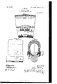
- Fig. 5 is a side elevational view,partly broken away to show the anticreeping device.
- Fig. 6 is a top plan view of a portion of the rim and side flange, showing the parts separated and transversely slotted for the accommodation of the anticreeping device; and Fig. 7 is a crosssectional view in two different transverse planes, illustrating a modification wherein one of the side flanges is integral with the rim and showing also a modified construction of fastener to prevent creeping.
- 5 designates the folly of a wheel
- 6 the rim-base, which, as shown in all the figures of the drawings, is a broad transversely-flat metal band afl'ording a wide substantial base to the tire-body.
- a pair of side rims or flanges 8 Secured to the opposite edges of the base 6, as by the screws 7, are a pair of side rims or flanges 8, and it will be observed as constituting a leading feature of the present invention that the inwardly-extending horizontal base portions of these members are made wedge-shaped in cross-section, being inclined downwardly and inwardly on their upper faces 8" in a direction transversely of the rimbase 6.
- I transversely slot the wedge-shaped bases of the side flanges inwardly from their inner edges at intervals, as shown at 13, and also preferably provide registering slots 14:, extending inwardly from the outer edges of the rim.
- slots 14 In the upper or both of these slots lie a series of bolts or pins 15, which at their upper ends are secured to the fastening wires or bands 10 in any suitable way, as by means of the sleeves 16, and at their lower ends project from the base of the tire.
- Figs. 3 and 1 illustrate a modification wherein the side flanges 8, in addition to the wedgeshaped bases already described, are provided at their outer ends with inwardly-turned projections 8 after the fashion of clencher-rims, and the twin halves of the tire-base are made correspondingly wedge-shaped on their outer faces, as shown at 9, to snugly lit between the oppositely-inclined projections 8 and bases 8 of the rim-flanges 8.
- rim-base as provided with inwardly-sloping removable side flange members on either side, respectively, yet it will be understood that one of these members on one side might be made integral with the rim-base without departing from the principle of the invention or sacrificing any of the advantages thereof.
- the tire is introduced to the rim by carrying both halves of the base over the flat free edge of the rim, (shown at the left,) for which purpose the anticreeping studs or bolts 15 extend only substantially flush with the rinrengaging surface of the tire-base on that side of the rim having the integral side flange, as shown, and said bolts 15 are internally threaded to receive fastening-bolts 17, inserted from beneath the rim through the slot in the integral rim and flange base.
- This style of two-part anticreeping-bolt may be substituted for the bolts 15, hereinbefore described in the constructions shown in the other figures of the drawings, if desired, or, as shown at the left in Fig. 7, the bolts 15 may be extended beneath or within the rim and provided with threaded ends engaged by nuts 20.
- I claim 1 The combination with a tire-body and a rim-base formed by a flat annular band, of side flange members on the opposite edges of said rim-base, said flange members each having an inwardly extending base portion, wedge-shaped in cross-section, and pointing inwardly of the rim seated on said rim-base and engaging the tire on its outer inclined surface whereby to automatically crowd the edges of the tire inwardly of the rim, substantially as described.
Landscapes
- Engineering & Computer Science (AREA)
- Mechanical Engineering (AREA)
- Tires In General (AREA)
Description
PATENTED JAN. 10, 1905.
J; NEARY. VEHICLE TIRE.
APPLICATION FILED MAY 28. 1904.
3 SHEETS-SHEET 1.
V 'II PATENTED JAN. 10, 1905. J. NEARY.
VEHICLE TIRE.
APPLIUATION FILED MAY 28. 1904.
3 SHEETS-SHEET 2.
PATENTED JAN. 10, 1905.
- J.NBARY.
7511mm, TIRE. APPLICATION FILED MAY 28. 1904.
3 SHEETS-SHEET 3.
UNITED STATES Patented January 10, 1905.
PATENT OFFICE.
.IOHN NEARY, OF KOKOMO, INDIANA, ASSIGNOR TO 'KOKOMO RUBBER COMPANY, OF KOKOMO, INDIANA, A CORPORATION OF INDIANA.
VEHICLE-TIRE.
SPECIFICATION forming part of Letters Patent No. 779,730, dated January 10, 1905.
Application filed May 28, 1904. Serial No. 210,252.
To all whom, it may concern:
Be it known that I, JOHN NEARY, a citizen of the United States, residing at Kolromo, in the county of Howard and State of Indiana, have invented certain new and useful Improvements in Vehicle-Tires, of which the following is a specification.
My invention relates to pneumatic tires for vehicles, and has reference more particularly to the heavy tires employed on the wheels of automobiles and motor-vehicles generally.
The principal object of the invention is to provide an improved means for securing the tire upon the rim which shall combine simplicity of construction with strength and efficiency in operation and at the same time render the matter of applying andremoving the tire a simple and easily-performed operation.
Another object of my invention is to provide an improved means for preventing creeping of the tire on the rim when partially or wholly deflated to prevent injury to the valvestem and inner tube. I
To these ends a leading feature of my invention consists of a tire and its seating and fastening means having as the chief novel and distinguishing characteristics a broad transversely-fiat rim in association with side flanges removably secured to one or both edges thereof and having wedgeshaped bases which point inwardly of the rim, presenting oppositely-inclined outer surfaces to seat the tire, in combination with a longitudinally-split hollow tire-body having its inner peripheral portion or base formed to seat upon the wedgeshaped bases of the flanges and under the internal pressure of the contained air be expanded into a close fit with the latter, at the same time drawing the fastening-wires outwardly and into a taut holding position upon the rim.
tire into or through its seat on the rim and so formed and arranged as to lock the tire against longitudinal creeping when wholly or partially deflated,while not interfering with the ready application of the tire to the rim.
My invention in two practicable forms thereof is illustrated in the accompanying drawings, wherein Figure l is a cross-sectional view of the tire and its rim when deflated. Fig. 2 is a perspective view in cross-section at one end of the same in an inflated position. Fig. 3 is a view similar to Fig. 1, showing a modified form wherein the inner air-holding tube may be omitted. Fig. 4: is a view corresponding to Fig. 2 of the form of tire shown in Fig. 3. Fig. 5 is a side elevational view,partly broken away to show the anticreeping device. Fig. 6 is a top plan view of a portion of the rim and side flange, showing the parts separated and transversely slotted for the accommodation of the anticreeping device; and Fig. 7 is a crosssectional view in two different transverse planes, illustrating a modification wherein one of the side flanges is integral with the rim and showing also a modified construction of fastener to prevent creeping.
Referring to the drawings, 5 designates the folly of a wheel, and 6 the rim-base, which, as shown in all the figures of the drawings, is a broad transversely-flat metal band afl'ording a wide substantial base to the tire-body.
Secured to the opposite edges of the base 6, as by the screws 7, are a pair of side rims or flanges 8, and it will be observed as constituting a leading feature of the present invention that the inwardly-extending horizontal base portions of these members are made wedge-shaped in cross-section, being inclined downwardly and inwardly on their upper faces 8" in a direction transversely of the rimbase 6.
9 designates the shell of the tire-body, which is longitudinally split on the central line of its base, the two halves 9 of the base being flat on their outer faces, as shown at 9, and inclined at substantially the same degree from the horizontal as the upper faces 8 of the wedge-shaped flange-bases, so as to engage and seat snugly upon the latter when the tire is inflated. Within the adjacent marginal portions of the tire are embedded a series of fastening wires or bands 10 and 11, and within the tire 9 is the usual inner air-retaining tube 12. I
As a means for preventing creeping of the tire on the rim when the former is partially or wholly deflated I transversely slot the wedge-shaped bases of the side flanges inwardly from their inner edges at intervals, as shown at 13, and also preferably provide registering slots 14:, extending inwardly from the outer edges of the rim. In the upper or both of these slots lie a series of bolts or pins 15, which at their upper ends are secured to the fastening wires or bands 10 in any suitable way, as by means of the sleeves 16, and at their lower ends project from the base of the tire.
The several parts are shown in deflated position in Fig. 1 and in inflated position in Fig. 2. In applying the tire to the rim the two sides of the split tire-body are distended sufiiciently to admit the flat rim between them, whereby the tire is caused to envelop the rim, and the two halves of the split base are then thrust inwardly over the edges of the rim, the pins or bolts 15, where these are employed, entering the slots 14:. The annular side flanges, each of which may be made in sections, if desired, are then applied by inserting their wedge-shaped bases beneath the base of the tire on either side, the slots 13 engaging the bolts, andare then secured to the rim-base 6 by the screws 7. Upon applying the internal air-pressure the side walls of the tirebody are distended, forcing the inner marginal portions 9 of the base into snug seating engagement with the vertical and inclined faces of the side flanges and their wedgeshaped bases, as clearly shown in Fig. 2, which action also carries the retaining- wires 10 and 11 outwardly into positions in which they snugly bind the'base of the tire-body upon the troughed face of the rim.
Figs. 3 and 1 illustrate a modification wherein the side flanges 8, in addition to the wedgeshaped bases already described, are provided at their outer ends with inwardly-turned projections 8 after the fashion of clencher-rims, and the twin halves of the tire-base are made correspondingly wedge-shaped on their outer faces, as shown at 9, to snugly lit between the oppositely-inclined projections 8 and bases 8 of the rim-flanges 8. In connection with this construction I nave shown a means for dispensing with the usual inner air-retaining tube, which consists in lining the inner surface of the members 8 and the outer surface of the rim 6 lying between them with a layer of soft rubber or equivalent material (indicated at 18) and extending the rubber surface of the tire-shell in a thin layer entirely around the rim-engaging surface of the base, as shown at 19, and also over the inner surface of the shell, so as to render the inner wall of the shell and the interlitting surfaces of the tirebase and rim air-proof under the internal pressure by the intimate contact of substances eapable of making an air-proof joint when forced together under sufficient pressure.
While I have shown the rim-base as provided with inwardly-sloping removable side flange members on either side, respectively, yet it will be understood that one of these members on one side might be made integral with the rim-base without departing from the principle of the invention or sacrificing any of the advantages thereof. Such a variation I have illustrated in Fig. 7 wherein one of the side flanges 8", with its slotted wedgeshaped base 8, is made integral with the rim 6'. In this case the tire is introduced to the rim by carrying both halves of the base over the flat free edge of the rim, (shown at the left,) for which purpose the anticreeping studs or bolts 15 extend only substantially flush with the rinrengaging surface of the tire-base on that side of the rim having the integral side flange, as shown, and said bolts 15 are internally threaded to receive fastening-bolts 17, inserted from beneath the rim through the slot in the integral rim and flange base. This style of two-part anticreeping-bolt may be substituted for the bolts 15, hereinbefore described in the constructions shown in the other figures of the drawings, if desired, or, as shown at the left in Fig. 7, the bolts 15 may be extended beneath or within the rim and provided with threaded ends engaged by nuts 20.
The feature of the anticreeping devices in any of the forms hereinabove described, and shown in the drawings, are also capable of use to good advantage without the wedge-shaped base members of the side flanges.
hile I have shown and described several mechanical embodiments of my invention, all of which are practical and useful, yet it is to be understood that these are by no meansv inclusive of all the detail forms and variations which the invention may comprehend, and consequently I do not limit the latter to such details except to the extent indicated in specific claims.
I claim 1. The combination with a tire-body and a rim-base formed by a flat annular band, of side flange members on the opposite edges of said rim-base, said flange members each having an inwardly extending base portion, wedge-shaped in cross-section, and pointing inwardly of the rim seated on said rim-base and engaging the tire on its outer inclined surface whereby to automatically crowd the edges of the tire inwardly of the rim, substantially as described.
2. The combination with a tire-body and a rim-base formed by a flat annular band, of side flange members secured to the opposite edges of said rim-base, said flange members each having an inwardly-extending base disposed transversely of the rim wedge-shaped in cross-section and oppositely-inclined tire-engaging surfaces. a radially-extending portion constituting a lateral abutment for the tire, and an inclined outer portion extending inwardly of the rim and constituting a clencher, substantially as described.
3. The combination with a tire-body and a rim-base formed by a flat annular band, of side flange members on the opposite edges of said rim-base having bases provided with inwardly and inversely inclined outer surfaces forming seats for the tire-base, and a lining of yielding material applied to said inclined surfaces and to the flat annular band between the inner edges of the inclines, substantially as described.
4E. The combination with a rim-base formed by a flat annular band, of clencher-shaped side flange members removably secured to the opposite edges of said rim-base and having bases provided with inwardly and inversely inclined outer surfaces forming seats for the tire-base, a lining of yieldable material applied to the internal walls of said side flange members and t0 the flat annular band between said members, and a tire-body split longitudinally of its inner periphery or base and having its internal surface and also its rim and flange engaging portions provided with a surface covering of soft rubber engaging the lining of the rim, substantially as described.
5. The combination with a tire-body having continuous fastening-wires, and a flat rim, of a series of pins or studs secured to said fastening-wires and projectinginwardly through the base of the tire into the rim to hold the tire against creeping, substantially as described.
6. The combination with a tire-body having continuous fastening-wires and a rim having inversely-inclined tire-engaging surfaces convergent in a direction toward the radial center of the rim, of a series of pins or studs rigidly united to said fastening-wires and projecting inwardly through the base of the tire into the rim to hold the tire against creeping, substantially as described.
7. The combination with a tire-body and a transversely-slotted rim, of a series of pins or studs incorporated in the tire-body during the process of manufacture and projecting from the base of the latter into the slots of the rim to secure the tire against creeping longitudinally of the rim, substantially as described.
8. The combination with a tire-body and a rim-base formed by a flat annular band, of side flange members on the opposite edges of said rim-base having wedge-shaped bases secured to thelatter and provided with inwardly and inversely inclined tire-engaging surfaces, and anticreeping devices anchored in the tirebody and extending through said flange-bases, substantially as describe v 9. The combination with a tire-body and a rim-base formed by a flat annular band, of side flange members on the opposite edges of said rim-base having wedge-shaped bases secured to the latter and provided with inwardly and inversely inclined tire-engaging surfaces, and bolts anchored in the tire-body and extending through said rim and flange bases to prevent creeping of the tire-body, substantially as described.
10. The combination with a tire-body and a rim-base formed by aflat annular band transversely slotted inwardly from its opposite edges, of side flange members on the opposite edges of said rim-base having wedge-shaped bases secured to the latter and provided with inwardly and inversely inclined tire-engaging surfaces and with transverse slots adapted to register with the slots of the rim-base, and bolts anchored in the tire-body and passing through and slidingly engaging said slots of the rim and flange bases to prevent creeping of the tire-body, substantially as described;
JOHN NEARY.
Witnesses:
B. C. LINCOLN, EDWIN ELLIS.
Priority Applications (1)
| Application Number | Priority Date | Filing Date | Title |
|---|---|---|---|
| US21025204A US779730A (en) | 1904-05-28 | 1904-05-28 | Vehicle-tire. |
Applications Claiming Priority (1)
| Application Number | Priority Date | Filing Date | Title |
|---|---|---|---|
| US21025204A US779730A (en) | 1904-05-28 | 1904-05-28 | Vehicle-tire. |
Publications (1)
| Publication Number | Publication Date |
|---|---|
| US779730A true US779730A (en) | 1905-01-10 |
Family
ID=2848214
Family Applications (1)
| Application Number | Title | Priority Date | Filing Date |
|---|---|---|---|
| US21025204A Expired - Lifetime US779730A (en) | 1904-05-28 | 1904-05-28 | Vehicle-tire. |
Country Status (1)
| Country | Link |
|---|---|
| US (1) | US779730A (en) |
Cited By (5)
| Publication number | Priority date | Publication date | Assignee | Title |
|---|---|---|---|---|
| US2427216A (en) * | 1942-06-09 | 1947-09-09 | Gen Tire & Rubber Co | Tire mounting rim |
| US2466449A (en) * | 1945-11-24 | 1949-04-05 | Letourneau Inc | Tire and rim assembly |
| US4153094A (en) * | 1977-02-28 | 1979-05-08 | Mckenzie Ross A | Sectional tire |
| US5151141A (en) * | 1991-03-28 | 1992-09-29 | The Goodyear Tire & Rubber Company | Tire and rim |
| US5968296A (en) * | 1997-05-30 | 1999-10-19 | Compagnie Generale Des Etablissements Michelin - Michelin & Cie | Tire having two wires in each bead |
-
1904
- 1904-05-28 US US21025204A patent/US779730A/en not_active Expired - Lifetime
Cited By (5)
| Publication number | Priority date | Publication date | Assignee | Title |
|---|---|---|---|---|
| US2427216A (en) * | 1942-06-09 | 1947-09-09 | Gen Tire & Rubber Co | Tire mounting rim |
| US2466449A (en) * | 1945-11-24 | 1949-04-05 | Letourneau Inc | Tire and rim assembly |
| US4153094A (en) * | 1977-02-28 | 1979-05-08 | Mckenzie Ross A | Sectional tire |
| US5151141A (en) * | 1991-03-28 | 1992-09-29 | The Goodyear Tire & Rubber Company | Tire and rim |
| US5968296A (en) * | 1997-05-30 | 1999-10-19 | Compagnie Generale Des Etablissements Michelin - Michelin & Cie | Tire having two wires in each bead |
Similar Documents
| Publication | Publication Date | Title |
|---|---|---|
| US779730A (en) | Vehicle-tire. | |
| US902212A (en) | Sectional tire. | |
| US1208902A (en) | Elastic vehicle-tire. | |
| US711081A (en) | Vehicle-wheel tire and fastening. | |
| US779731A (en) | Vehicle-tire. | |
| US1004582A (en) | Tire for vehicle-wheels. | |
| US1524114A (en) | Tire | |
| US1323457A (en) | Vehicle-wheel tike ahd bim | |
| US597612A (en) | Island | |
| US1043208A (en) | Means for mounting punctureless tires on wheel-rims. | |
| US1424314A (en) | Vehicle wheel | |
| US735265A (en) | Detachable tire. | |
| US796894A (en) | Tire and rim. | |
| US600781A (en) | Adolf gunther | |
| US1096842A (en) | Vehicle-tire. | |
| US803053A (en) | Tire. | |
| US795652A (en) | Vehicle-tire. | |
| US783219A (en) | Pneumatic tire. | |
| US590095A (en) | Thomas dunn | |
| US715305A (en) | Pneumatic tire. | |
| US1234004A (en) | Vehicle-tire. | |
| US977589A (en) | Fastening device for vehicle-tires. | |
| US1116120A (en) | Wheel-tire for road-vehicles. | |
| US1160323A (en) | Vehicle wheel-tire. | |
| US1277516A (en) | Vehicle-tire. |