US856490A - Ironing-board. - Google Patents
Ironing-board. Download PDFInfo
- Publication number
- US856490A US856490A US36136007A US1907361360A US856490A US 856490 A US856490 A US 856490A US 36136007 A US36136007 A US 36136007A US 1907361360 A US1907361360 A US 1907361360A US 856490 A US856490 A US 856490A
- Authority
- US
- United States
- Prior art keywords
- board
- supports
- ironing
- flexible
- ears
- Prior art date
- Legal status (The legal status is an assumption and is not a legal conclusion. Google has not performed a legal analysis and makes no representation as to the accuracy of the status listed.)
- Expired - Lifetime
Links
- 210000005069 ears Anatomy 0.000 description 6
- 238000010409 ironing Methods 0.000 description 5
- 238000010276 construction Methods 0.000 description 3
- 238000006073 displacement reaction Methods 0.000 description 1
Images
Classifications
-
- A—HUMAN NECESSITIES
- A47—FURNITURE; DOMESTIC ARTICLES OR APPLIANCES; COFFEE MILLS; SPICE MILLS; SUCTION CLEANERS IN GENERAL
- A47B—TABLES; DESKS; OFFICE FURNITURE; CABINETS; DRAWERS; GENERAL DETAILS OF FURNITURE
- A47B3/00—Folding or stowable tables
Definitions
- This invention relates to ironing boards and its object is to provide foldable devices of this character which are simple, (l1 rable and eflicient in construction and which can be readily adjusted to different elevations.
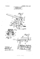
- Figure 1 is a perspective view of the device in position for use;
- Fig. 2 is a side elevation showing the device folded;
- Fig. 3 is an enlarged section on line 0cac, Fig. 2.
- 1 is the main board of the device which may be of any desired size or contorr and has a cross plate 2 secured to the bottom face thereof near one end and provided with downwardly turned ears 3.
- Pivot bolts 1 extend through these ears and mounted upon these bolts and between the ears are diverging supports 5 suitably connected or braced near their lower ends as shown at 6.
- Another set of diverging supports 7 is pivotally mounted on the bolts 4 and upon the outer faces of the ears 3 and these supports are also connected by a cross brace S.
- the supports 5 and 7 are so proportioned that when the device is folded said supports 5 assume positions between the supports 7. Any suitable means such as nuts 9 may be provided for holding the bolts 4 against displacement.
- Each of the supports 5 and 7 has an opening 10 therein and threaded through these openings is a flexible adjusting device 11 in the form of a rope, or other suitable flexible connection.
- a loop 12 may be formed at one end of this connection to receive the other end of said connection in which a number of knots 13 may be formed. These knots are adapted to prevent the end of the connection from slipping through the loop 12 and ob viously by manipulating this connection so Specification of Letters Patent.
- a rope, chain or other flexible device 14- is placed in engagement with the supports 5 and is adapted to detachably engage a hook 15 extending from one end of the board.
- this device is formed of heavy rope the same is provided with knots as shown at 16 to prevent it from slipping through the hook, but if it should consist of a chain it is obvious that any ofthe links of the chain could be placed in engagement with the hook and no knots would be necessary.
- a spacing block 17 is secured on one end of the board 1 and.
- an auxiliary board 18 is hinged upon and adapted to be supported by this block.
- the board 18 is designed for use in ironing sleeves and small garments, and when not in use it can be swung out of the way over the end of the board 1.
- An ironing board comprising pivotally connected supports, a flexible adjusting and holding device loosely engaging the supports, said device having means at the ends thereof for holding said ends together, a board pivotally mounted on the supports, and a flexible device for adjustably connecting the board with one of the supports.
- An ironing board comprising foldable supports, flexible means loosely engaging the supports and having its ends adjustably connected for holding the supports in predetermined positions, a board pivotally mounted on the supports, a flexible holding device connected to one of the supports, and means upon the board for adjustably engaging said device.
Landscapes
- Treatment Of Fiber Materials (AREA)
Description
.:No. 856,490, ,PATBNTED JUNE'll, 1907.
' w. PIGKFORD & B. 11mm.
IRONING BOARD.
' APPLICATION nun nuts, 1007.,
2 V/ A hi! 2 A TTOR/VE Y5 UNITED STATES PATENT oFFIoE.
WILLIAM PIOKFORD AND EDWARD DERR, OF SEGUNDO, COLORADO.
lRONlNG-BOARD.
0 all whom it may concern:
Be it known that we, WILLIAM PICKFORD and EDWARD DERR, citizens of the United States, residing at Segundo, in the county of Las Animas and State of Colorado, have invented a new and useful Ironing-Board, of which the following is a specification.
This invention relates to ironing boards and its object is to provide foldable devices of this character which are simple, (l1 rable and eflicient in construction and which can be readily adjusted to different elevations.
I Vith these and other objects in view the invention consists of certain novel feats res of construction and combinations of parts which will be hereinafter more fully described and pointed out in the claims.
Inthe accompanying drawings is shown the preferred form of the invention.
In said drawings: Figure 1 is a perspective view of the device in position for use; Fig. 2 is a side elevation showing the device folded; and Fig. 3 is an enlarged section on line 0cac, Fig. 2.
Referring to the figures by characters of reference, 1 is the main board of the device which may be of any desired size or contorr and has a cross plate 2 secured to the bottom face thereof near one end and provided with downwardly turned ears 3. Pivot bolts 1 extend through these ears and mounted upon these bolts and between the ears are diverging supports 5 suitably connected or braced near their lower ends as shown at 6. Another set of diverging supports 7 is pivotally mounted on the bolts 4 and upon the outer faces of the ears 3 and these supports are also connected by a cross brace S. The supports 5 and 7 are so proportioned that when the device is folded said supports 5 assume positions between the supports 7. Any suitable means such as nuts 9 may be provided for holding the bolts 4 against displacement. Each of the supports 5 and 7 has an opening 10 therein and threaded through these openings is a flexible adjusting device 11 in the form of a rope, or other suitable flexible connection. A loop 12 may be formed at one end of this connection to receive the other end of said connection in which a number of knots 13 may be formed. These knots are adapted to prevent the end of the connection from slipping through the loop 12 and ob viously by manipulating this connection so Specification of Letters Patent.
Patented June 11, 1907.
A lication fil d March 8, 1907. Serial No. 361,360.
as to place different knots in engage ment with the loop the supports 5 and 7 can be held at desired distances apart so as to hold the board at any suitable distance from the floor. Obviously if a chain is employed in lieu of a rope such as shown a hook could be connected to it for engaging the links instead of knotting and looping the connection in the nLanner shown. This construction is so obvious that it is not deemed necessary to illustrate it.
In order that the board 1 may be held in a horizontal position after it has been adjusted to a desired height a rope, chain or other flexible device 14- is placed in engagement with the supports 5 and is adapted to detachably engage a hook 15 extending from one end of the board. 'hen this device is formed of heavy rope the same is provided with knots as shown at 16 to prevent it from slipping through the hook, but if it should consist of a chain it is obvious that any ofthe links of the chain could be placed in engagement with the hook and no knots would be necessary.
A spacing block 17 is secured on one end of the board 1 and. an auxiliary board 18 is hinged upon and adapted to be supported by this block. The board 18 is designed for use in ironing sleeves and small garments, and when not in use it can be swung out of the way over the end of the board 1.
It will be noted that when the device is not in use it can be folded into a compact bundle as shown in Fig. 2. Importance is attached to the simple means for adjusting the board vertically as it dispenses with the use of hinges, bolts and the like such as have heretofore been found necessary in order to secure a proper adjustment.
hat is claimed is:
1. An ironing board comprising pivotally connected supports, a flexible adjusting and holding device loosely engaging the supports, said device having means at the ends thereof for holding said ends together, a board pivotally mounted on the supports, and a flexible device for adjustably connecting the board with one of the supports.
2. An ironing board comprising foldable supports, flexible means loosely engaging the supports and having its ends adjustably connected for holding the supports in predetermined positions, a board pivotally mounted on the supports, a flexible holding device connected to one of the supports, and means upon the board for adjustably engaging said device.
3. The combination with a board having depending ears; of supports pivotally mounted upon'the inner and outer faces of the ears respectively, one of said supports being foldable into the other support, flexible means loosely engaging the supports and having its ends adjustably connected for limiting the movement of the supports away from each I other, and a flexible holding device upon one of the supports and adjustably engaging the board. t
In testimony that We claim the foregoing as our own, We have hereto affixed our signatures in the presence of tWo Witnesses.
WILLIAM PIOKFORD. EDWARD DERR. Witnesses:
WM. W. BOYLE,
J. V. TIMBLIN.
Priority Applications (1)
| Application Number | Priority Date | Filing Date | Title |
|---|---|---|---|
| US36136007A US856490A (en) | 1907-03-08 | 1907-03-08 | Ironing-board. |
Applications Claiming Priority (1)
| Application Number | Priority Date | Filing Date | Title |
|---|---|---|---|
| US36136007A US856490A (en) | 1907-03-08 | 1907-03-08 | Ironing-board. |
Publications (1)
| Publication Number | Publication Date |
|---|---|
| US856490A true US856490A (en) | 1907-06-11 |
Family
ID=2924945
Family Applications (1)
| Application Number | Title | Priority Date | Filing Date |
|---|---|---|---|
| US36136007A Expired - Lifetime US856490A (en) | 1907-03-08 | 1907-03-08 | Ironing-board. |
Country Status (1)
| Country | Link |
|---|---|
| US (1) | US856490A (en) |
-
1907
- 1907-03-08 US US36136007A patent/US856490A/en not_active Expired - Lifetime
Similar Documents
| Publication | Publication Date | Title |
|---|---|---|
| US856490A (en) | Ironing-board. | |
| US1066371A (en) | Suspended clothes-rack. | |
| US1090837A (en) | Clothes-drier. | |
| US1135181A (en) | Adjustable washstand. | |
| US848086A (en) | Flat-car stanchion. | |
| US811587A (en) | Decoy. | |
| US782461A (en) | Lawn-hose support. | |
| US855493A (en) | Swing. | |
| US965112A (en) | Adjustable flood-gate. | |
| US286431A (en) | Stack-roof | |
| US762658A (en) | Adjustable scaffold for ladders. | |
| US1083994A (en) | Seed-corn hanger. | |
| US1161062A (en) | Display apparatus. | |
| US1156603A (en) | Display device. | |
| US1079513A (en) | Seed-rack. | |
| US457114A (en) | Clothes-drier | |
| US1057997A (en) | Support for bridge-planks. | |
| US1099906A (en) | Hammock-support. | |
| US1237835A (en) | Gate. | |
| US664148A (en) | Ironing-board. | |
| US1052791A (en) | Hoisting apparatus. | |
| US964019A (en) | Cable-roller. | |
| US467058A (en) | Wall-paper display-rack | |
| US1033394A (en) | Farm-gate. | |
| US1130603A (en) | Corn-loom. |