US856488A - Insulator. - Google Patents
Insulator. Download PDFInfo
- Publication number
- US856488A US856488A US29847406A US1906298474A US856488A US 856488 A US856488 A US 856488A US 29847406 A US29847406 A US 29847406A US 1906298474 A US1906298474 A US 1906298474A US 856488 A US856488 A US 856488A
- Authority
- US
- United States
- Prior art keywords
- bracket
- spring
- insulator
- aperture
- sides
- Prior art date
- Legal status (The legal status is an assumption and is not a legal conclusion. Google has not performed a legal analysis and makes no representation as to the accuracy of the status listed.)
- Expired - Lifetime
Links
Images
Classifications
-
- H—ELECTRICITY
- H01—ELECTRIC ELEMENTS
- H01B—CABLES; CONDUCTORS; INSULATORS; SELECTION OF MATERIALS FOR THEIR CONDUCTIVE, INSULATING OR DIELECTRIC PROPERTIES
- H01B17/00—Insulators or insulating bodies characterised by their form
- H01B17/20—Pin insulators
Definitions
- My invention pertains especially to insulators for telephone and telegraph wires, but it is' obvious that it may be employedwherever f a conductorfor electricity is required, and it the spring'havea bearing upon the edges of formish'ape tothe spring. ⁇
- I construct my support of achannel bar, tor the reason that the slot is much easier formed, and the coils of the channel'bar, thus 'affording a very strong and durable devicepand giving a more unil 4
- I avo'id the breaking of a glass insulator, such as are commonly used, as the snialler end -of the coiled 'spring is ⁇ made vsomewhat larger than the smaller end -oi the screwthreadedopening in the insulator, so that the insulator maybe screwed tight to -the support without th'eend of the support coming in contact therewith.
- a further advantage lies in the slot iii the support which permits a longitudinal movementor .the spring, relative' to the support, to counter-act 'the expansion and contrae.
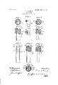
- FIG. 1 is an elevatioiial view of my device iii the preferred forni, with one end of the bracket broken away
- Fig. 2 is an elevational view of the bracket with one eiid broken away, and de.- signed to show the longitudinal slot and the ends of the bracket before swaging
- Fig. 3 is an edge view of Fig. 1, Fig.
- FIG. 4 is a top view of Fig. 1,' Figs. 5 and 6 are modified forms ol my device; Figs. 7 and 8 are top views o'l Figs. and 6 respectively; and Fig. 9 is an elevational' view ⁇ of a double bracket attached to a suitable support.
- , 10 represents a channel bar forming the bracket, capable of being attached to a wall or the like and' provided at one endwith a slot 11, which is open at one end as shown at 12.
- the sides of the bracket, iii the preferred forni, are cut away at 13 and 14 to i'orni the ears and 16 so that the ends may be. readily and easily swage d.
- '17 is a coiled spring sligl'itly tapered, as
- a slot I provide elongated apertures 24 and 25 which permits the ready insertion 4oi: the ends of the spring ,utilizationof a spring, as a connecting means between the insulator and a bracket, but
- bracket formed of a strip provided withaii kelongated aperture in one of its'sides, and a l tapered spring coiled around said bracket IOO having one of its ends in said aperture and its sides in contact with the edges of said bracket, substantially as described.
- a bracket formed of a channel strip and provided with an elongated aperture in one of its sides, and a tapered spring coiled around said bracket having one of its ends in said aperture and its sides in contact with the edges of said bracket, substantially as described.
- a bracket formed of a channel strip and provided with a slot open at one end, and a tapered spring coiled around said bracket, hav ing its ends within said aperture, and retained therein by swaging over the ends of said bracket, substantially as described.
- a bracket formed of a channel strip and pro'- vided with an elongated aperture in one of its sides, and a tapered springl coiled around said bracket and having its ends bent to substantially bisect the interior space of said spring, said ends being adapted to slide within said aperture, and retained. therein by swaging eeeflse over the ends of said bracket, substantially as described. 5.
- a bracket formed of a channel strip and pro'- vided with an elongated aperture in one of its sides, and a tapered springl coiled around said bracket and having its ends bent to substantially bisect the interior space of said spring, said ends being adapted to slide within said aperture, and retained. therein by swaging eeeflse over the ends of said bracket, substantially as described. 5.
- a bracket formed of a channel strip and pro'- vided with an elongated aperture in one of its sides, and a tapered springl coiled around said bracket and having its ends bent to substantially bise
- bracket formed of a channel strip and probracket, substantially as described.
- bracket formed of a channel strip and provided with an elongated aperture in o ne of its l sides, op'en at one end, a tapered spring coiled around ,said bracket and provided with inturned ends, said ends being adaptedto slide within said aperture and retained therein by swaging over the outer end oi said bracket, substantially as described.
Description
No. 856,488. PATENTED JUNE ll, 1907.
G. L. PRIEUR. JR.
NSULATO'R.
APPLIGATION FILED JAN.29,1906.
UNITED STATES PATENT OFFICE.
CHARLES L. PEIRCE, JR., OF CHICAGO, ILLINOIS, ASSIGNOR TO PEIRCE SPECIALTY COMPANY, OF CHICAGO, ILLINOIS, A CORPORATION OF iLLiN'ois.
INSULATOR.
Specication of Letters Patent.
Patented June 1 1, 1907.
Application led January 29. IQG. Serial No. 298,474.
To LZ wlw/n, llt may concern.
Beit known that I, CHARLES L. Pinnen, Jr., a citizen of the United States, residing at Chicago, in the county of Cook and State of Illiiiois, have invented certain new and useful Improvements in `Insulators, of which the following is a speciiication.
n My invention pertains especially to insulators for telephone and telegraph wires, but it is' obvious that it may be employedwherever f a conductorfor electricity is required, and it the spring'havea bearing upon the edges of formish'ape tothe spring.`
consists in the preferred form of a spring member taperingly coiled," and having its ends bent to substantially bisect the interior .space of the coil, in combination with a channel bar support, slottedat one ei'id, andwithin which the bent ends' of the spring are run and retained lthereinby swaging over the open ends of the support. Y
. YIn the preferred form I construct my support of achannel bar, tor the reason that the slot is much easier formed, and the coils of the channel'bar, thus 'affording a very strong and durable devicepand giving a more unil 4 By such a construction I avo'id the breaking of a glass insulator, such as are commonly used, as the snialler end -of the coiled 'spring is `made vsomewhat larger than the smaller end -oi the screwthreadedopening in the insulator, so that the insulator maybe screwed tight to -the support without th'eend of the support coming in contact therewith. u
A further advantage lies in the slot iii the support which permits a longitudinal movementor .the spring, relative' to the support, to counter-act 'the expansion and contrae.
tion of the' glass insulator, which variation frequently results in vits destruction.v Fur-- the structure, and the exceptional cheapiiess 'and rapiditywith whichY it can be manufactured, Adue tothe shape of thebracket which permits a ready 'formation of thev aperturey.and Vthe insertion otthe ends of the 'springs Referring to the drawing Figure 1 is an elevatioiial view of my device iii the preferred forni, with one end of the bracket broken away Fig. 2 is an elevational view of the bracket with one eiid broken away, and de.- signed to show the longitudinal slot and the ends of the bracket before swaging; Fig. 3 is an edge view of Fig. 1, Fig. 4 is a top view of Fig. 1,' Figs. 5 and 6 are modified forms ol my device; Figs. 7 and 8 are top views o'l Figs. and 6 respectively; and Fig. 9 is an elevational' view` of a double bracket attached to a suitable support.
, 10 represents a channel bar forming the bracket, capable of being attached to a wall or the like and' provided at one endwith a slot 11, which is open at one end as shown at 12. The sides of the bracket, iii the preferred forni, are cut away at 13 and 14 to i'orni the ears and 16 so that the ends may be. readily and easily swage d.
'17 is a coiled spring sligl'itly tapered, as
shown at Fig. 1, and liavingits ends 18 and 19A bent to bisect the interior space oi' the coil, said ends resting on the opposite sides of the coil from the bends, as shown at 2() and 21. The spring is then passed over the bracket and forced down upon the saine, the ends 1S and 1.() sliding within the slot 11 and retained therein by swaging in the ears 15 and 16, as shown at 22, the inner sides of the spring resting upon the edges oi the bracket at 23and 24, In Fig. 5 instead ol" a slot I provide elongated apertures 24 and 25 which permits the ready insertion 4oi: the ends of the spring ,utilizationof a spring, as a connecting means between the insulator and a bracket, but
What I c'laini and wish to secure by Letters Patent is z 1. In combination with an insulator, a'
bracket formed of a strip provided withaii kelongated aperture in one of its'sides, and a l tapered spring coiled around said bracket IOO having one of its ends in said aperture and its sides in contact with the edges of said bracket, substantially as described.
2. In combination with an insulator, a bracket formed of a channel strip and provided with an elongated aperture in one of its sides, and a tapered spring coiled around said bracket having one of its ends in said aperture and its sides in contact with the edges of said bracket, substantially as described.
3. In combination with an insulator, a bracket formed of a channel strip and provided with a slot open at one end, and a tapered spring coiled around said bracket, hav ing its ends within said aperture, and retained therein by swaging over the ends of said bracket, substantially as described.
4. In combination with aninsulator, a bracket formed of a channel strip and pro'- vided with an elongated aperture in one of its sides, and a tapered springl coiled around said bracket and having its ends bent to substantially bisect the interior space of said spring, said ends being adapted to slide within said aperture, and retained. therein by swaging eeeflse over the ends of said bracket, substantially as described. 5. In combination with an insulator, a
bracket formed of a channel strip and probracket, substantially as described.
6. In 'combination with an insulator, a
bracket formed of a channel strip and provided with an elongated aperture in o ne of its l sides, op'en at one end, a tapered spring coiled around ,said bracket and provided with inturned ends, said ends being adaptedto slide within said aperture and retained therein by swaging over the outer end oi said bracket, substantially as described.
CHARLES L. PEIECE, JR.
Witnesses: y
FREDERICK C. GOODWIN, JAMES R. OFFIELD.
Priority Applications (1)
| Application Number | Priority Date | Filing Date | Title |
|---|---|---|---|
| US29847406A US856488A (en) | 1906-01-29 | 1906-01-29 | Insulator. |
Applications Claiming Priority (1)
| Application Number | Priority Date | Filing Date | Title |
|---|---|---|---|
| US29847406A US856488A (en) | 1906-01-29 | 1906-01-29 | Insulator. |
Publications (1)
| Publication Number | Publication Date |
|---|---|
| US856488A true US856488A (en) | 1907-06-11 |
Family
ID=2924943
Family Applications (1)
| Application Number | Title | Priority Date | Filing Date |
|---|---|---|---|
| US29847406A Expired - Lifetime US856488A (en) | 1906-01-29 | 1906-01-29 | Insulator. |
Country Status (1)
| Country | Link |
|---|---|
| US (1) | US856488A (en) |
Cited By (1)
| Publication number | Priority date | Publication date | Assignee | Title |
|---|---|---|---|---|
| US2438237A (en) * | 1944-01-07 | 1948-03-23 | Alamo Corp | Fence knob |
-
1906
- 1906-01-29 US US29847406A patent/US856488A/en not_active Expired - Lifetime
Cited By (1)
| Publication number | Priority date | Publication date | Assignee | Title |
|---|---|---|---|---|
| US2438237A (en) * | 1944-01-07 | 1948-03-23 | Alamo Corp | Fence knob |
Similar Documents
| Publication | Publication Date | Title |
|---|---|---|
| US1046573A (en) | Electric-light bracket. | |
| US1800254A (en) | Handle and the like | |
| US961352A (en) | Curtain-rod. | |
| US856488A (en) | Insulator. | |
| US1155835A (en) | Electrical scroll-saw. | |
| US916435A (en) | Support for electric wires or conductors. | |
| US821062A (en) | Wire and insulator holder. | |
| US686605A (en) | Automatic tension-coupling and sound-deadener. | |
| US491262A (en) | Combined thread holder and cutter | |
| GB191118707A (en) | Improvements in Knot Holders for the Cords of Window Blinds. | |
| US1421734A (en) | Commutator | |
| US729418A (en) | Handle-bar. | |
| US980495A (en) | Wire-retainer and insulator-guard. | |
| US1022993A (en) | Insulator. | |
| US833135A (en) | High-tension terminal for spark-coils. | |
| US756026A (en) | Insulator. | |
| US1005786A (en) | Spring fastening device. | |
| US809982A (en) | Electric safety-fuse. | |
| US764389A (en) | Reel. | |
| US1201066A (en) | Stop for wire-insulators. | |
| US990269A (en) | Thermometer receptacle or case. | |
| US972267A (en) | Pigtail connection for carbon brushes. | |
| US1528458A (en) | Fuse plug | |
| US1048587A (en) | Wire-holder for insulators. | |
| US731426A (en) | Ring-bushing for interior conduits. |