US856486A - Driving mechanism for automobiles. - Google Patents
Driving mechanism for automobiles. Download PDFInfo
- Publication number
- US856486A US856486A US24030205A US1905240302A US856486A US 856486 A US856486 A US 856486A US 24030205 A US24030205 A US 24030205A US 1905240302 A US1905240302 A US 1905240302A US 856486 A US856486 A US 856486A
- Authority
- US
- United States
- Prior art keywords
- driving
- vehicle body
- links
- motor
- axle
- Prior art date
- Legal status (The legal status is an assumption and is not a legal conclusion. Google has not performed a legal analysis and makes no representation as to the accuracy of the status listed.)
- Expired - Lifetime
Links
- 238000010276 construction Methods 0.000 description 7
- 230000005540 biological transmission Effects 0.000 description 6
- 230000000630 rising effect Effects 0.000 description 4
- 102000004726 Connectin Human genes 0.000 description 1
- 108010002947 Connectin Proteins 0.000 description 1
- 241000208225 Rhus Species 0.000 description 1
- 235000014220 Rhus chinensis Nutrition 0.000 description 1
- 206010043268 Tension Diseases 0.000 description 1
- 229910052729 chemical element Inorganic materials 0.000 description 1
- 230000006835 compression Effects 0.000 description 1
- 238000007906 compression Methods 0.000 description 1
- 238000006073 displacement reaction Methods 0.000 description 1
- 239000000725 suspension Substances 0.000 description 1
Images
Classifications
-
- B—PERFORMING OPERATIONS; TRANSPORTING
- B62—LAND VEHICLES FOR TRAVELLING OTHERWISE THAN ON RAILS
- B62D—MOTOR VEHICLES; TRAILERS
- B62D21/00—Understructures, i.e. chassis frame on which a vehicle body may be mounted
- B62D21/02—Understructures, i.e. chassis frame on which a vehicle body may be mounted comprising longitudinally or transversely arranged frame members
Definitions
- This invention relates to improvements in driving-mechanisms for automobiles and refers more specifically to'improvement's in the driving train connecting the driven wheels of a vehicle with the prime mover or motor.
- the salient object of the invention is to provide a construction in which the motor may be mounted upon a spring supported vehicle body and operatively connected with the traction wheels in such manner that vertical displacement of the motor relatively to the driven traction member or members does not result in disarranging the proper driving connections between the motor and driven member or members.
- Subsidiary objects of the invention are to so mount an intermediate element of the drivingtrain that it will automatically ad just itself to maintain the proper relation of all of the elements of the train during the movement of the motor relatively to the ultimate driven traction member; to rovide a construction and arrangement of parts which avoids the bringing of torsional or cramping stresses upon any part of the, drivin train, thereby securing the maximum e ciency of the motor effort; to provide a construction in which a counter shaft forming an intermediate member of the driving train is suspended by means of planet links which Specification of Letters Patent.
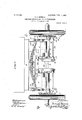
- Figure 1 is a rear endelevation of a vehicle equipped with a preferred embodiment of the invention
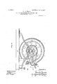
- Fig. 2 is a transverse sectional view taken a proximately on line 2-2 of Fig. 1 and loolimg in the direction of the arrows.
- two traction wheels are mounted to rotate independently upon 'a main axle 2, and separate motors 3 and 4; respectively are arranged to drive the respective wheels;
- the motor casing Upon the bottom of the vehicle body is sccured a suspension frame 8 com rising a transverse bar-like 'member 9 and integral end hanger portions 10.
- the motor casing s their main shafts 12 parallel with the main axle 2 of the vehicle.
- the motors 3 and 4 are electric motors in the present embodiment, and their armature shafts constitute their main drive shafts; the ends of said armature shafts being journaled in the ends of the outer motor casing. 12, as'usual.
- the armature shaft of eachmotoi is at one end extended beyond the main casing 12 and provided with a rigid driving pinion 13 which internieshes with a spur gear 14 mounted upon a counter shaft 15 arranged below the motor.
- I provide a pair of planet links 16 16 the upper of the motors 3 and 4 are rigidly bolted to the I bar 9, as indicated at 11, with the axes of ends of which are pivotally supported upon hub-like extensions 17 18 of the motor frame, wh ch extensions are concentric with the mam armature shaft;
- the planet links 16 are provided with suitable journal bearings 19 '19 for the counter shaft and arealso extended beyond said journal bearings and desirably connected by means of a stay rod 2( whereby they are maintained at a defimte distance apart at their outer ends.
- distance-rods 24 are arranged to con' nect the lanet links with the axle 2 of the vehicle; tfiese distance-rods being arranged to extend in an approximately direct line between the centers of the gears 21 and 23.
- each link is provided with an ear or connection lug 25 with which one end of the distance-rod is pivotally connected, and u on the axle is mounted a bracket 26, to W ich-the oppo site ends of the distance-rod issimilarly connected.
- each is provided intermediate its length with a.
- a driving mechanism for automobiles comprlsmg a vehicle running ear provided with a main axle, a traction w eel ,mounted upon said axle, a spring-supported"vehicle body carried by the running gear, a motor carried by said vehicle body at, a point longi tudinally removed from thetaxle, a driving.
- a driving mechanism for automobiles comprising a vehicle running gear provided with a main axle, atraction wheel mounted .upon said axle, a spring-supported vehicle body carried by thev running gear, a motor carried'by said vehicle body at a point longie tudinally removed from the axle, a driving shaft directly driven by said motor and mounted uponthe vehicle body to extend parallel with the axis of rotation of the tracwheel, driving connections between said lat :2 ter element and the transmission element, a
- distance member provided intermediate its length with a-turn-buckle and connects d with .the link construction and with the vehicie axle, respectively, and a connection'bar ex-' sumac tending between the outer ends of said links mounted on the ends of said axle, a springsupported vehicle body carried by the running gear, a pair of independent motors car-' ried by said vehicle body at points longitudinally removed from the axle, a pair ofindependent driving shafts directly driven by 'said motors, respectively, and mounted upon the vehicle body to extend parallel with the axis of rotation of the traction wheels, a pair of planet links pivotally mounted concentric ally with each of said drivin shafts, respectively, shafts carried by sai links'arranged parallel with the axis of the driving shafts,
- stay rods connectin the free ends of said links, transmission e ements mounted upon the shafts carried bythe links, drivin connections between the motors and sai lastnamed shafts, driving "elements rigidly mounted concentrically upon the traction wheels, driving connections between the latter and said transmission elements, and longit'udinally adjustable distance members con nected with saidlinks and vehicle axle, substantially as described. 2
Landscapes
- Engineering & Computer Science (AREA)
- Chemical & Material Sciences (AREA)
- Combustion & Propulsion (AREA)
- Transportation (AREA)
- Mechanical Engineering (AREA)
- Retarders (AREA)
Description
PATENTBD JUNE 11, 1907.
I F. J. NEWMAN.
DRIVING MECHANISM FOR AUTOMOBILES.
APPLICATION FILED JAN. 9, 1905.
. BEETS-SHEET 1.
No. 856,486. PATENTED JUNE 11,1907' P. J. NEWMAN.
DRIVING MECHANISM FOR AUTOMOBILES.
APPLIOATION FILED JAN. 9, 1905.
2 SHEETS-SHEET 2v UNI ED STATES E T OFFICE.
FREDERICK J.-NEWM.'AN, OF CHICAGO, ILLINOIS, ASSIGNOR TO WOODS --MOTOR VEHICLE COMPANY, OF CHICAGO, ILLINOIS, A CORPORA- TION OF ILLINOIS.
DRIVING MECHANISM FOR AUTUWIOBBLES.
ToaZZ whom it may concern.-
, Be it known that I, FREDERICK J. NEW-- MAN, a citizen of the United States, residing in Chicago, in the county of Cook and State.
of Illinois, have invented certain new and useful Improvements in Driving Mechanlsms for Automobiles, of which-the following is a specification.
This invention relates to improvements in driving-mechanisms for automobiles and refers more specifically to'improvement's in the driving train connecting the driven wheels of a vehicle with the prime mover or motor.
The salient object of the invention is to provide a construction in which the motor may be mounted upon a spring supported vehicle body and operatively connected with the traction wheels in such manner that vertical displacement of the motor relatively to the driven traction member or members does not result in disarranging the proper driving connections between the motor and driven member or members.
Subsidiary objects of the invention are to so mount an intermediate element of the drivingtrain that it will automatically ad just itself to maintain the proper relation of all of the elements of the train during the movement of the motor relatively to the ultimate driven traction member; to rovide a construction and arrangement of parts which avoids the bringing of torsional or cramping stresses upon any part of the, drivin train, thereby securing the maximum e ciency of the motor effort; to provide a construction in which a counter shaft forming an intermediate member of the driving train is suspended by means of planet links which Specification of Letters Patent.
Application filed January 9, 1905. Serial No- 240,30 2.
- Patented iTune 11, 1 907.
Figure 1 is a rear endelevation of a vehicle equipped with a preferred embodiment of the invention; Fig. 2 is a transverse sectional view taken a proximately on line 2-2 of Fig. 1 and loolimg in the direction of the arrows.
In the embodiment illustrated two traction wheels, designated l 1, are mounted to rotate independently upon 'a main axle 2, and separate motors 3 and 4; respectively are arranged to drive the respective wheels; the
motors being mounted. upon or suspended from the vehicle body, designated as a whole 5, and the latter being spring supported from the running gear as usual. The par ticular construction and arrangement of the springs, by means of which the vehicle body is supported from the running gear, form no part of the present invention, but it is sufficient to say that these sprin s are, as usual, so arranged that the up andd own movement of the vehicle body relatively to the axle is confined to movement in vertical planes, or substantially so. In the instance illustrated a set of lon itudinally disposed side springs 6 and a single transverse spring 7 connected with the rear ends of the side springs form the spring support for the rear end of the vehicle body.
Upon the bottom of the vehicle body is sccured a suspension frame 8 com rising a transverse bar-like 'member 9 and integral end hanger portions 10. The motor casings their main shafts 12 parallel with the main axle 2 of the vehicle. The motors 3 and 4 are electric motors in the present embodiment, and their armature shafts constitute their main drive shafts; the ends of said armature shafts being journaled in the ends of the outer motor casing. 12, as'usual. The armature shaft of eachmotoi is at one end extended beyond the main casing 12 and provided with a rigid driving pinion 13 which internieshes with a spur gear 14 mounted upon a counter shaft 15 arranged below the motor.
In order to support the counter shaft 15 in parallel relation to the armature shaft and movably, so that it may maintain a definite relation to the main axle of the vehicle, I providea pair of planet links 16 16 the upper of the motors 3 and 4 are rigidly bolted to the I bar 9, as indicated at 11, with the axes of ends of which are pivotally supported upon hub-like extensions 17 18 of the motor frame, wh ch extensions are concentric with the mam armature shaft; The planet links 16 are provided with suitable journal bearings 19 '19 for the counter shaft and arealso extended beyond said journal bearings and desirably connected by means of a stay rod 2( whereby they are maintained at a defimte distance apart at their outer ends.
Upon each traction wheel, and concen trically with its axis ofrotation, is'rigidiy secured .a sprocket-wheel 21, and these I sprocket-wheels 21 are operatively connected with the counter shafts 15 of the respective motors by means of chain belts 22 connect ing the gears 21 with smaller sprocket gears 23 rigidly mounted upon the respective counter shafts 15in plane alinement with the gears 21'. I
In order to maintain the counter shaft in proper relation to the gears 21 regardless of buckle 2-7. m
the rising and falling movements of the 'mo tors, distance-rods 24 are arranged to con' nect the lanet links with the axle 2 of the vehicle; tfiese distance-rods being arranged to extend in an approximately direct line between the centers of the gears 21 and 23. In the. particular instance illustrated each link is provided with an ear or connection lug 25 with which one end of the distance-rod is pivotally connected, and u on the axle is mounted a bracket 26, to W ich-the oppo site ends of the distance-rod issimilarly connected. In order to provide for adjustment of the lengths of thedistance-rods each is provided intermediate its length with a. turn-' The two gears 13 and 14 of each motor are shown as inclosed within a suitable housing '28; it being understood that these housings are mounted so as to be capable of planet movement with the counter shaft and planet links,'although it will be obvious that said housings may be madelarge enough to accommodate the relative movements of the gears therein, in which case the housings may be rigidly mounted.
panie The operation of the mechanism con structed and arranged as described will-be entirely obvious from the foregoing description. It may be noted, however, that any bodily rising or falling movement of the motors with the vehicle body due'to compression or ex anslon of the springs will be accomplanet links around the armature shafts; the counter shafts in such rising and falling movements being compelled to move in an are concentric with the mainaxle '2 or axes of the gears '21. This, of course, maintains the driving belts at their regular adjusted ten sion and avoids the bringing of torsional stresses upon the driving tram there by securing'the maximum efficiency from the motors.
preferred and by a slight angular change of the While I have herein shown and described a,
ra'cticalv embodiment of the invention, yet it will be" obvious'thatthe details of construction! and arrangement, may be modified Without departing from the in vention and Ijdo not therefore limit myself to such details, except to the extent that they are made the subject'of specific claims.
- I' claim as my invention:
1. A driving mechanism. for automobiles comprlsmg a vehicle running ear provided with a main axle, a traction w eel ,mounted upon said axle, a spring-supported"vehicle body carried by the running gear, a motor carried by said vehicle body at, a point longi tudinally removed from thetaxle, a driving.
shaft directly driven by said motor and mounted upon the vehicle body to extend parallel with the axis of rotation of the traction wheel, a pair of planet links journaled concentrically with said driving shaft and lo.- cated at separated points longitudinally ,of
the driving shaft, a shaft .joifrnaled intermediate the free ends of said links and arranged parallel with the axis of the driving shaft, a stay rod connecting the free ends of said links, a transmission element mounted upon the shaft carried by the links, driving connections between 'said transmission element and driving shaft, a driving element rigidly mounted concentrically upon the traction Wheel,' driving connections a between said latter ele -ment and the transmission element, and a dis tance member connected with the link construction and with the vehicle axle, substan tially as described. i I 2. A driving mechanism for automobiles comprising a vehicle running gear provided with a main axle, atraction wheel mounted .upon said axle, a spring-supported vehicle body carried by thev running gear, a motor carried'by said vehicle body at a point longie tudinally removed from the axle, a driving shaft directly driven by said motor and mounted uponthe vehicle body to extend parallel with the axis of rotation of the tracwheel, driving connections between said lat :2 ter element and the transmission element, a
distance member provided intermediate its length with a-turn-buckle and connects d with .the link construction and with the vehicie axle, respectively, and a connection'bar ex-' sumac tending between the outer ends of said links mounted on the ends of said axle, a springsupported vehicle body carried by the running gear, a pair of independent motors car-' ried by said vehicle body at points longitudinally removed from the axle, a pair ofindependent driving shafts directly driven by 'said motors, respectively, and mounted upon the vehicle body to extend parallel with the axis of rotation of the traction wheels, a pair of planet links pivotally mounted concentric ally with each of said drivin shafts, respectively, shafts carried by sai links'arranged parallel with the axis of the driving shafts,
and'journaled above the free ends thereof,
stay rods connectin the free ends of said links, transmission e ements mounted upon the shafts carried bythe links, drivin connections between the motors and sai lastnamed shafts, driving "elements rigidly mounted concentrically upon the traction wheels, driving connections between the latter and said transmission elements, and longit'udinally adjustable distance members con nected with saidlinks and vehicle axle, substantially as described. 2
FREDERICK J. NEWM Witnesses: I
FREDERICK C. Goonwm, JAMES R. OFFIELD,
Priority Applications (1)
| Application Number | Priority Date | Filing Date | Title |
|---|---|---|---|
| US24030205A US856486A (en) | 1905-01-09 | 1905-01-09 | Driving mechanism for automobiles. |
Applications Claiming Priority (1)
| Application Number | Priority Date | Filing Date | Title |
|---|---|---|---|
| US24030205A US856486A (en) | 1905-01-09 | 1905-01-09 | Driving mechanism for automobiles. |
Publications (1)
| Publication Number | Publication Date |
|---|---|
| US856486A true US856486A (en) | 1907-06-11 |
Family
ID=2924941
Family Applications (1)
| Application Number | Title | Priority Date | Filing Date |
|---|---|---|---|
| US24030205A Expired - Lifetime US856486A (en) | 1905-01-09 | 1905-01-09 | Driving mechanism for automobiles. |
Country Status (1)
| Country | Link |
|---|---|
| US (1) | US856486A (en) |
Cited By (1)
| Publication number | Priority date | Publication date | Assignee | Title |
|---|---|---|---|---|
| US2511252A (en) * | 1945-01-17 | 1950-06-13 | Fernandez Manuel | Independent wheel suspension |
-
1905
- 1905-01-09 US US24030205A patent/US856486A/en not_active Expired - Lifetime
Cited By (1)
| Publication number | Priority date | Publication date | Assignee | Title |
|---|---|---|---|---|
| US2511252A (en) * | 1945-01-17 | 1950-06-13 | Fernandez Manuel | Independent wheel suspension |
Similar Documents
| Publication | Publication Date | Title |
|---|---|---|
| US2212453A (en) | Motor vehicle | |
| US856486A (en) | Driving mechanism for automobiles. | |
| US568779A (en) | Electric locomotive | |
| US833478A (en) | Power-transmission mechanism for automobiles. | |
| US799264A (en) | Motor suspension for electric motors. | |
| US773575A (en) | Automobile. | |
| US567560A (en) | bagnall | |
| US1112678A (en) | Motor-vehicle. | |
| US267405A (en) | debes | |
| US729010A (en) | Vehicle driving mechanism. | |
| US843796A (en) | Automobile-gearing. | |
| US773480A (en) | Automobile-frame. | |
| US699808A (en) | Motor-vehicle. | |
| US441771A (en) | Frank mansfield | |
| US424207A (en) | Electrically-propelled vehicle | |
| US451155A (en) | Electrically-propelled car | |
| US684535A (en) | Motor-vehicle. | |
| US1311928A (en) | Mechanism tor railway-vehicles with electric motors rigidly | |
| US650837A (en) | Balance-gearing for automobiles. | |
| US783599A (en) | Running-gear for motor-vehicles. | |
| US749165A (en) | Motor-vehicle | |
| US810674A (en) | Vehicle-motor-suspension mechanism. | |
| US756152A (en) | Motor-vehicle. | |
| US699427A (en) | Motor-vehicle. | |
| US656483A (en) | Motor-vehicle. |