US856482A - Toilet device. - Google Patents
Toilet device. Download PDFInfo
- Publication number
- US856482A US856482A US34059200A US1900340592A US856482A US 856482 A US856482 A US 856482A US 34059200 A US34059200 A US 34059200A US 1900340592 A US1900340592 A US 1900340592A US 856482 A US856482 A US 856482A
- Authority
- US
- United States
- Prior art keywords
- rolls
- powder
- rod
- receptacle
- faces
- Prior art date
- Legal status (The legal status is an assumption and is not a legal conclusion. Google has not performed a legal analysis and makes no representation as to the accuracy of the status listed.)
- Expired - Lifetime
Links
Images
Classifications
-
- B—PERFORMING OPERATIONS; TRANSPORTING
- B67—OPENING, CLOSING OR CLEANING BOTTLES, JARS OR SIMILAR CONTAINERS; LIQUID HANDLING
- B67D—DISPENSING, DELIVERING OR TRANSFERRING LIQUIDS, NOT OTHERWISE PROVIDED FOR
- B67D1/00—Apparatus or devices for dispensing beverages on draught
- B67D1/08—Details
- B67D1/12—Flow or pressure control devices or systems, e.g. valves, gas pressure control, level control in storage containers
- B67D1/1202—Flow control, e.g. for controlling total amount or mixture ratio of liquids to be dispensed
- B67D1/1234—Flow control, e.g. for controlling total amount or mixture ratio of liquids to be dispensed to determine the total amount
- B67D1/124—Flow control, e.g. for controlling total amount or mixture ratio of liquids to be dispensed to determine the total amount the flow being started or stopped by means actuated by the vessel to be filled, e.g. by switches, weighing
Definitions
- My invention is an improved toilet device ada ted for holding powdered material and disc arging the same in proper quantities 'for use.
- Fig. 2- is a detached view of the internal mechanism of the canister with the brushlocating push-rod, powder agitator and discharge-rolls in their normal position:
- Fig. 3- is a detached view of the internal meel anism of the canister showing ⁇ the push-rod and agitator elevated by means of a toothbrush, a broken section of the brush being shown, which operation has turned the rolls and discharged a portion of the powder onto the brush:
- Fig. 7- is a broken sectional view of the canister, and end view of the dischargerolls closed:
- Fig. 10- is a detail perspective view of the powder agitator:
- Fig. 114 is a detail end elevation of the discharge-rolls in their normal closed position: Fig.
- 1 represents the powder canister having the removable cover 2.
- This canister may, if desired, be supported in a suitable bracket, for which purpose the projection 6 on the cover 2 would be convenient.
- the internal mechanism of the device consists, essentially, of the discharge-rolls 12 and 13, Fig. 0, having the journals 12'TL and 13, two of which journals are mounted in the bracket 14 attached to the. base 15 and the other two are mounted in holes, not shown, in the side wall 16 of the housing 17.
- 18 is a push-rod adapted to operate through an aperture, not shown, in the top 19 of said housing and also the base 15, 2() and 21, Fig. 4, are links pivotally connected by one end to the pin 22 projecting from the said pushrod, and b y the other end to the crank-pins 23 and 24 or the discharge-rolls.
- 25 and 26, Fig. 5 are crescent shaped openings in the end. wall 16 of said.
- FIG. 1 is a curved projection at the lower end of the said push-rod adapted to receive the neck portion of the toothbrush 11 as shown at Figs. 1 and 3, for the purpose to be hereinafter more fully described.
- 2S and 29 are stop-pins projecting from the push-rod to limit the vertical movement of said rod, and 30 is a retractible spring for returning the position.
- the discharge-rolls have the ilat faces 12b and 13b, and they are so journaled that their circumferential surfaces will register together. Therefore, when in their normal position, shown at Fig. 7, their Hat faces will 'form an obtuse angle and thus provide a receptacle or pocket for the powder from the canister to fall into preparatory to its being discharged therefrom.
- the tendency of some powder to pack renders it necessary, especially in tooth-powder, which is of a soapy nature, to provide means whereby the mass is continuously disturbed by agitation every time the push-rod is operated.
- the agitation for this purpose consists of the blades 31, 32, 33, 34 and 35, Fig.
- the base plate 15 is located within the canister so as to form the skirt 1u, Fig. 7, thus leaving room for the admission of the brush.
- 44 are spring arms depending from said plate and 45 are pins projecting therefrom adapted to enter holes, not shown, in the said skirt.
- the neck of the brush is inserted in the forked end 27 of the push-rod 18, thus centrally locating it with respect to the discharging point of the rolls, then, with a slight upwardpressure, said rod is elevated, the rolls turned and a winrow of powder is deposited upon the brush as shown at Fig. 3.
- rlhe stop 29 is so placed on such push-rod that the wet brush is not carried up far enough to come in contact with the rolls or the base plate, or, in fact, with any part of the device, thus enabling any number of persons to use the same device without the least danger of contamination.
- Figs. 11, 12, and 13 are seen the three principal positions that the discharge-rolls will occupy in performing their functions.
- the rolls as before stated, are in their normal position with the space b, embraced within the angle formed by the straight faces of the rolls, filled with powder, see also Fig. 7. It is not advisable nor intended that all the powder embraced within this angle should be discharged at once. Therefore, when the rolls are rotated toward leach other they will deposit an exact quantity of powder on the brush and do this every time without fail. As the rolls rotate toward each other, the straight faces thereof will force all of the powder in excess of what is held between such faces, when they reach the vertical position shown at Fig.
- the device as above described forms a neat, handy and sanitary article for toilet purposes and one in which all the members of a family or patrons of hotels, Steamship lines and sleeping cars can use with perfect safety without fear of contamination.
- my device fully overcomes. It possesses the advantage of being able to deliver an even quantity of material each time, as the construction of the rolls are such that no variation in lthis respect can take place.
- the novel feature of locating the brush so as to bring it central with the central construction or meeting faces of the rolls makes the matter of always depositing the powder directly on the brush, absolutely certain. l
- Other means for operating the rolls and the agitator could be substituted for those shown without departing from the spirit of my invention.
- a base therefor having an opening therein, cylindrical rolls journaled over such opening and having fiat faces adapted to form an angle for the reception of the powdered material when said rolls are in their normal position, said rolls adapted, when rotated, to gather a portion of said powdered material and deposit the same outside the receptacle, for the purpose set forth.
- the combination with a receptacle adapted to hold powdered material, of a pair of reciprocating discharge-rolls located at or near the bottom of said receptacle, flat or substantially flat faces on said rolls, said rolls adapted to reciprocate between the extreme outer edges of said flat faces so that, when said flat faces are within the receptacle they will form a pocket to receive the loose powder, and when brought to a vertical position they will exert sufficient pressure on the powder to cause it to be discharged in a semi-compact form, for the purpose set forth.
Description
PATENTED JUNE 11, 1907.
K. LOVELL. TOILET DEVIQE. AnrLIoA'rIoN FILED JUNE 19. 1900. RBNEWBD 00T. 25. 19o6.
Z SHEETS-SHEET 1.
A non/vn W/ TNE SSE S THE Nowjus PETERS co., wAsmNoroN, D. c.
No. 856,482. PATENTEAI) JUNE 11, 1907. A. K. LOVELL..
TOILET DEVICE.
APPLIOATION FILED JUNE 1e. 1900. BENBWED 00T. 25, 190e.
2 SHEETS-SHEET 2.
@Gavi/) B), K Q ..z/@6% A Tron/vm vus Ncmms PETERS co.. wAsmNcroN. D. cy
ALBERT K. LOVELL, OF NEW YORK, N. Y.
Specification of Letters Patent.
Patented June 11, 1907.
Application filed June 19,1900. Renewed October 25,1906. Serial No. 340.592.
To @ZZ whom t mfr/,y concern:
Be it known that I, ALBERT K. LovELL, a citizen of the United States, and a resident of New York, in the county of New York and State of New York, have invented certain new and useful Improvements in Toilet Devices, of which the following is a specification.
My invention is an improved toilet device ada ted for holding powdered material and disc arging the same in proper quantities 'for use. The detailed construction of which -will be more fully set forth in the following specification.
To enable others to understand my invention, reference is had to the accompanying' drawings in which:
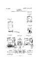
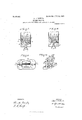
Figure l-isafront elevation of the toothpowder canister' showing a brush in position to receive a discharge of powder therefrom: Fig. 2-is a detached view of the internal mechanism of the canister with the brushlocating push-rod, powder agitator and discharge-rolls in their normal position: Fig. 3-is a detached view of the internal meel anism of the canister showing` the push-rod and agitator elevated by means of a toothbrush, a broken section of the brush being shown, which operation has turned the rolls and discharged a portion of the powder onto the brush: 'F ig. Li-is a sectional view of the housing in which the push-rod operates, through line c of Fig. 2: Fig. 5-is a sectional view of the push-rod housing with the push-rod and its mechanism removed: t ig. -is a detail plan view of the dischargerolls: Fig. 7-is a broken sectional view of the canister, and end view of the dischargerolls closed: Fig. S-is a view similar to Fig. 7 showing the discharge-rolls open: Fig. 9-is a bottom plan view of the base in which the discharge-rolls are mounted, also a sectional view of the push-rod: Fig. 10-is a detail perspective view of the powder agitator: Fig. 114is a detail end elevation of the discharge-rolls in their normal closed position: Fig. 12-is a detail end elevation of the discharge-rolls partially open with their straight faces in a vertical position showing a quantity of powder between said faces: lig. 13-is a detail end elevation of the dischargerolls reversed, or open, and in the act of discharging their contents.
Its construction and operation are as follows:
1 represents the powder canister having the removable cover 2. This canister may, if desired, be supported in a suitable bracket, for which purpose the projection 6 on the cover 2 would be convenient.
The internal mechanism of the device consists, essentially, of the discharge- rolls 12 and 13, Fig. 0, having the journals 12'TL and 13, two of which journals are mounted in the bracket 14 attached to the. base 15 and the other two are mounted in holes, not shown, in the side wall 16 of the housing 17. 18 is a push-rod adapted to operate through an aperture, not shown, in the top 19 of said housing and also the base 15, 2() and 21, Fig. 4, are links pivotally connected by one end to the pin 22 projecting from the said pushrod, and b y the other end to the crank- pins 23 and 24 or the discharge-rolls. 25 and 26, Fig. 5, are crescent shaped openings in the end. wall 16 of said. housing 17, to afford free play for the reciprocating movement of the said crank-pins. 27 is a curved projection at the lower end of the said push-rod adapted to receive the neck portion of the toothbrush 11 as shown at Figs. 1 and 3, for the purpose to be hereinafter more fully described. 2S and 29 are stop-pins projecting from the push-rod to limit the vertical movement of said rod, and 30 is a retractible spring for returning the position.
The discharge-rolls have the ilat faces 12b and 13b, and they are so journaled that their circumferential surfaces will register together. Therefore, when in their normal position, shown at Fig. 7, their Hat faces will 'form an obtuse angle and thus provide a receptacle or pocket for the powder from the canister to fall into preparatory to its being discharged therefrom. The tendency of some powder to pack renders it necessary, especially in tooth-powder, which is of a soapy nature, to provide means whereby the mass is continuously disturbed by agitation every time the push-rod is operated. The agitation for this purpose consists of the blades 31, 32, 33, 34 and 35, Fig. 10, forming the lower rectangle and the blades 36, 37, 38 and 39 forming a smaller rectangle immediately above. These blades are attached to the uprights 40 and 411 depending from the horizontal rod 42 projecting 'from the pushrod as shown at Figs. 2 and 3. The vertical movement, therefore, of the said push-rod will carry the said blades th'rough the mass of powdered m'atcri al and loosen it up so that rod to its normal` IOO IIO
it will fiow freely into the embrace of the discharge-rolls. 43, Fig. 9, is an opening in the base plate 15 through which the powder is discharged, and the rolls are so placed with respect to'such opening that no powder can escape except through the proper channel.
The base plate 15 is located within the canister so as to form the skirt 1u, Fig. 7, thus leaving room for the admission of the brush. 44 are spring arms depending from said plate and 45 are pins projecting therefrom adapted to enter holes, not shown, in the said skirt.
In operating the device, the neck of the brush is inserted in the forked end 27 of the push-rod 18, thus centrally locating it with respect to the discharging point of the rolls, then, with a slight upwardpressure, said rod is elevated, the rolls turned and a winrow of powder is deposited upon the brush as shown at Fig. 3. rlhe stop 29 is so placed on such push-rod that the wet brush is not carried up far enough to come in contact with the rolls or the base plate, or, in fact, with any part of the device, thus enabling any number of persons to use the same device without the least danger of contamination.
In Figs. 11, 12, and 13, are seen the three principal positions that the discharge-rolls will occupy in performing their functions. In Fig. 11 the rolls, as before stated, are in their normal position with the space b, embraced within the angle formed by the straight faces of the rolls, filled with powder, see also Fig. 7. It is not advisable nor intended that all the powder embraced within this angle should be discharged at once. Therefore, when the rolls are rotated toward leach other they will deposit an exact quantity of powder on the brush and do this every time without fail. As the rolls rotate toward each other, the straight faces thereof will force all of the powder in excess of what is held between such faces, when they reach the vertical position shown at Fig. 12, back in the direction of arrow c so that, when the rolls are in the position shown in Fig. 12, the space between said vertical faces will be iilled with powder and, as the rolls continue to rotate, the corners CZ and c will gradually come together and cut off the powder above, and the powder between the said vertical faces will be discharged when the rolls are in the reverse position shown at Fig. 13 and the powder will fall upon the brush in the compact form g, which compact form is' due to the pressure exerted thereon by the vertical faces when the same are in the position shown at Fig. 12. When the rolls are in their reverse position shown at Fig. 13, the powder in the canister will fill the space f, bounded by the curved exterior of the rolls, and when the said rolls return to their normal position, the powder will readily fill the space l) as before mentioned.
The device as above described forms a neat, handy and sanitary article for toilet purposes and one in which all the members of a family or patrons of hotels, Steamship lines and sleeping cars can use with perfect safety without fear of contamination. There are devices where the brush is inserted directly into the powder, but this dangerous practice my device fully overcomes. It possesses the advantage of being able to deliver an even quantity of material each time, as the construction of the rolls are such that no variation in lthis respect can take place. The novel feature of locating the brush so as to bring it central with the central construction or meeting faces of the rolls, makes the matter of always depositing the powder directly on the brush, absolutely certain. l Other means for operating the rolls and the agitator could be substituted for those shown without departing from the spirit of my invention.
l/Vhile I show an agitator for loosening the powder in all of the devices, I do not, however, wish to be strictly confined to its use wh ere the rolls ha ve straight faces, as, in such cases, the natural jar the device would get while using it would answer fairly well although, even in such cases, an agitator is no objection.
Having thus described my invention, what I claim as new and desire to secure by Letters Patent is:
1. The combination, in a device of the character described, of a receptacle for holding powdered material adapted to be discharged therefrom in predetermined quantities, cylindrical rolls having iiat faces adapted to be presented to the powdered material in the said receptacle when in their normal position, means for rotating said rolls so that the powdered material within said faces will be carried without the receptacle, for the purpose set forth.
2. The combination, in a device of the character described, of a receptacle for holdlOO IIO
ing powdered material adapted to be discharged therefrom in predetermined quantities, a base therefor having an opening therein, cylindrical rolls journaled over such opening and having fiat faces adapted to form an angle for the reception of the powdered material when said rolls are in their normal position, said rolls adapted, when rotated, to gather a portion of said powdered material and deposit the same outside the receptacle, for the purpose set forth.
3. The combination, in a device of the character described, of a receptacle for holding powdered material, a base having an aperture therein, cylindrical rolls having fiat faces journaled over said aperture, said iiat faces set at an angle within said receptacle to receive the powdered material, a push rod, means for connecting said push rod with said rolls so that, when said push rod is actuated the rolls will be rotated so as to gather in a portion of such material between said flat faces and deposit the same outside the receptacle. for the purpose set forth.
4. The combination, in a device of the character described, of a receptacle for holding powdered material adapted to be discharged therefrom in predetermined quantities, cylindrical rolls having flat faces for the purpose described, a base having an opening therein said rolls journaled in close proximity to said aperture, a push rod for operating said rolls, an agitator connected with said push rod, for the purpose set forth.
5. The combination, in a device of the character described, of a receptacle for holding powdered material adapted to be dis- Acharged therefrom in predetermined quantities, cylindrical rolls registering together and provided with flat faces, for the purpose described, a base having an openingA therein, said rolls journaled in close proximity to such opening, a push rod adapted to aetuate said rolls, means on the said push rod for locating a tooth brush or other like article with respect to such opening, for the purpose set forth.
6. The combination, in a device of the character described, of a receptacle for holding powdered material adapted to be discharged therefrom in predetermined quantities, cylindrical rolls registering together, flat faces on said rolls for the purpose described, a base having an opening therein, said rolls in close proximity to such opening, said base set within the said receptacle far enough to form a skirt below said base, a push rod connected with said rolls and adapted to aetuate the same, means on the lower end of said push rod for locating a tooth brush or other like article with respect to said opening, for the purpose set forth.
7. The combination, in a device of the character described, of a receptacle for holding powdered material adapted to be discharged therefrom in predetermined quantities, cylindrical rolls having flat faces for the purpose described, a base set within said receptacle so as to form an open skirt below said base, an opening in said base for the discharge of powder, a push rod adapted to actuate said rolls which rolls are placed in close proximity 'to said opening, means at the lower end of said rod for locating a tooth brush or other like article with respect to such opening, an agitator connected with said rod, for the purpose set forth.
8. rlhe combination, in a device of the character described, of a receptacle for holding powdered material adapted to be discharged therefrom, discharge rolls transversely located within said receptacle, a push rod adapted to actuate said rolls, a base located within said receptacle far enough to form a well defined skirt below such base, an opening in said base, said rolls in close proximity therewith, means on the lower end of said rod `for locating a tooth brush with respect to said opening, means for limiting the upward movement 'of said push rod so that the brush will avoid Contact with said base, for the purpose set forth.
9. In a device of the character described, the combination, with a receptacle adapted to hold powdered material, of a pair of reciprocating discharge-rolls located at or near the bottom of said receptacle, flat or substantially flat faces on said rolls, said rolls adapted to reciprocate between the extreme outer edges of said flat faces so that, when said flat faces are within the receptacle they will form a pocket to receive the loose powder, and when brought to a vertical position they will exert sufficient pressure on the powder to cause it to be discharged in a semi-compact form, for the purpose set forth.
Signed at Bridgeport in the county of Fairfield and State of Connecticut this 8th day of June A. D. 1900.
ALBERT K. LOVELL.
Titnessesz L. R. HOYT, S. G. MEEKER.
Priority Applications (1)
| Application Number | Priority Date | Filing Date | Title |
|---|---|---|---|
| US34059200A US856482A (en) | 1900-06-19 | 1900-06-19 | Toilet device. |
Applications Claiming Priority (1)
| Application Number | Priority Date | Filing Date | Title |
|---|---|---|---|
| US34059200A US856482A (en) | 1900-06-19 | 1900-06-19 | Toilet device. |
Publications (1)
| Publication Number | Publication Date |
|---|---|
| US856482A true US856482A (en) | 1907-06-11 |
Family
ID=2924937
Family Applications (1)
| Application Number | Title | Priority Date | Filing Date |
|---|---|---|---|
| US34059200A Expired - Lifetime US856482A (en) | 1900-06-19 | 1900-06-19 | Toilet device. |
Country Status (1)
| Country | Link |
|---|---|
| US (1) | US856482A (en) |
Cited By (1)
| Publication number | Priority date | Publication date | Assignee | Title |
|---|---|---|---|---|
| US2609942A (en) * | 1949-06-06 | 1952-09-09 | Northwest Nut Growers | Feeding, positioning, and orienting mechanism |
-
1900
- 1900-06-19 US US34059200A patent/US856482A/en not_active Expired - Lifetime
Cited By (1)
| Publication number | Priority date | Publication date | Assignee | Title |
|---|---|---|---|---|
| US2609942A (en) * | 1949-06-06 | 1952-09-09 | Northwest Nut Growers | Feeding, positioning, and orienting mechanism |
Similar Documents
| Publication | Publication Date | Title |
|---|---|---|
| US1802284A (en) | Measuring and dispensing device | |
| US856482A (en) | Toilet device. | |
| US1765622A (en) | Dispensing device | |
| US2824667A (en) | Portable combination container and dispenser | |
| US1728526A (en) | Dispensing apparatus | |
| US2402707A (en) | Dispensing apparatus | |
| US1127520A (en) | Sugar-vending machine. | |
| US1639415A (en) | Dispenser | |
| US1345865A (en) | Dispensing-machine | |
| US589775A (en) | Island | |
| US1369740A (en) | Rotary measuring device | |
| US1172603A (en) | Measuring and dispensing device. | |
| US853768A (en) | Measuring device. | |
| US1286223A (en) | Measuring and dispensing device. | |
| US1239753A (en) | Vending-machine. | |
| US1173768A (en) | Sugar-bowl. | |
| US2024037A (en) | Abrasive cleaner dispenser | |
| US701980A (en) | Receptacle for holding and delivering aromatic substances. | |
| US2209707A (en) | Powder dispenser | |
| US1502992A (en) | Sanitary dispensing measure | |
| US614646A (en) | William i-l cloud | |
| US1400757A (en) | Sugar-dispenser | |
| US1105797A (en) | Dispensing device. | |
| US502453A (en) | Spice-box | |
| US752735A (en) | Wilhelm weise |