US856449A - Continuous glass-melting pot. - Google Patents
Continuous glass-melting pot. Download PDFInfo
- Publication number
- US856449A US856449A US33952906A US1906339529A US856449A US 856449 A US856449 A US 856449A US 33952906 A US33952906 A US 33952906A US 1906339529 A US1906339529 A US 1906339529A US 856449 A US856449 A US 856449A
- Authority
- US
- United States
- Prior art keywords
- partition
- chamber
- glass
- pot
- continuous glass
- Prior art date
- Legal status (The legal status is an assumption and is not a legal conclusion. Google has not performed a legal analysis and makes no representation as to the accuracy of the status listed.)
- Expired - Lifetime
Links
- 238000006125 continuous glass melting process Methods 0.000 title description 4
- 238000005192 partition Methods 0.000 description 16
- 239000011521 glass Substances 0.000 description 10
- 238000010276 construction Methods 0.000 description 6
- 239000000463 material Substances 0.000 description 5
- 238000002844 melting Methods 0.000 description 5
- 230000008018 melting Effects 0.000 description 5
- 150000001875 compounds Chemical class 0.000 description 2
- 238000010438 heat treatment Methods 0.000 description 2
- 238000004519 manufacturing process Methods 0.000 description 2
- 238000001035 drying Methods 0.000 description 1
- 239000012535 impurity Substances 0.000 description 1
- 238000007689 inspection Methods 0.000 description 1
- 239000011819 refractory material Substances 0.000 description 1
- 239000002893 slag Substances 0.000 description 1
- 230000003245 working effect Effects 0.000 description 1
Images
Classifications
-
- F—MECHANICAL ENGINEERING; LIGHTING; HEATING; WEAPONS; BLASTING
- F27—FURNACES; KILNS; OVENS; RETORTS
- F27B—FURNACES, KILNS, OVENS OR RETORTS IN GENERAL; OPEN SINTERING OR LIKE APPARATUS
- F27B14/00—Crucible or pot furnaces
- F27B14/08—Details specially adapted for crucible or pot furnaces
- F27B14/10—Crucibles
Definitions
- This invention relates to melting pots, of the class known as continuous melting pots, or devices of this character wherein the compound for producing the glass is fed continuously thereto at one point and re moved continuously therefrom at another point, and has for its object to improve the construction and increase utility, and economy of construction and operation of devices of this character.
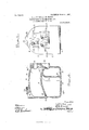
- Figure 1 is a front elevation of the improved device.
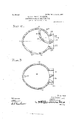
- Fig. 2 is a section on the line 22 of Fig. 1.
- Fig. 3 is a section on the line 3-3 of Fig. 1.
- Fig. 4 is a section on the line i-4 of Fig. 2.
- the improved device is constructed in on single mass of the refractory material usually employed in manufacturing melting pots for glass and for similar purposes, and comprises a body portion represented as a whole at 10 with a concave bottom 11, vertical side walls 12 and a dome like top 13.
- the improved. body is designed to be located within the furnace in the usual manner.
- the body portion of the device is some what egg-shaped transversely, as represented in Figs. 2 and 3, andfor the purpose of this description, the larger end of the body will be referred to as the front of the device and the smaller portion as the rear of the device.
- an upwardly curved partition 14 Disposed intermediate the interior of the de vice is an upwardly curved partition 14, the latter being lowest at the rear end of the body, as shown in Fig. 4.
- This partition divides the pot into a fusing chamber 14 and a gathering chamber 19, a curved partition 19 connecting the bottom 11 and partition 14, and subdividing the gathering chamber to furnish a working chamber 19
- a feed aperture 15 Leading through the front portion of the body above the partition 14 is a feed aperture 15 through which the material for producing the glass is inserted and deposited upon the partition 14.
- the forward end of the partition, or that adjacent to the feed aperture or mouth 15 forms, in conjunction with the front wall of the pot a pocket 15, that operates to retain any slag or impurities present, so that all of the stock that escapes from the fusing chamber is free from any foreign matter that would detract from the commercial value of the product.
- Leading through the dome-like top 13 at the smaller rear end is an inlet 'l'lue 16 through which a portion of the heating medium enters the fusing chamber above the partition 1%, and piercing the front wall of the body is an outlet llue 17, the latter being connected in any suitable manner with the draft chimney or stack, the latter not being shown as it forms no part of the present invention.
- a discharge aperture 18 through which the melted glass flows to the gathering chamber and thence to the working chamber through one or more apertures 20 as hereafter explained.
- Piercing the front wall of the body and communicating with the working chamber is an aperture 21, and through which the glass may be gatherei in the usual manner.
- Piercing the front wall of the body ad.- j acent to the gathering aperture 21 is another aperture 22 communicating with the gathering chamber below the partition 14, to provide means of access thereto when required.
- the apertures 2122 are provided with detachable closures of the usual construction, but they are not shown as they form no part of the present invention and as their construction is so well known.
- the apertures 21-22 are surrounded by guard hoods 2L24, and the feed aperture 15 is also provided with a guard hood 25.
- the Walls of the device may be of any required thickness, and the device may be of any required size or capacity.
- the operation is as follows: The compound from which the glass is manufactured is fed in through the aperture 15, as above described and deposited upon the partition 14. As fast as the glass is melted, it runs down through the aperture 18 into the gathering chamber, and thence through the apertures 20 into the working chamber 21 from which it may be removed in the ordinary manner, the supply of material being continuous as required through the feed aperture 15.
- the melting operation is contin-
- the supply of glass in the working chamber is thus uniform, and may be maintained at any required height by keeping up the supply of material in the feed aperture 15, as will be obvious.
- the supply may be maintained in the working chamber at a uniform depth so that the operators can reach the material at the same point in the chamber at all times, which thus does not vary materially.
- a closing tile or damper 26 is provided, which may be employed to partially or wholly cover the inlet flue 16 and thus effectually control the supply of the auxiliary heating medium.
- the aperture 22 permits the inspection of the gathering chamber of the lower portion and clearing of the same when required.
- the device is simple in construction, is
- a one-piece glass melting pot of substantially ovoidal form in horizontal section having an arched top, a concaved bottom and an intermediate arched partition forming within the pot an upper fusing chamber, the space below said partition being subdivided by a vertical transversely curved partition into a rear gathering chamber and a front work ing chamber, said intermediate partition having at its rear end a discharge opening leading from the fusing to the gathering chamber, and the vertical partition having at its lower edge openings leading from the gathering to the working chamber, said pot being provided at its front with a charging opening leading to the fusing chamber, and a gas escape opening leading therefrom and with a pair of hooded openings communicating respectively with the gathering and working chambers, there being formed in the top wall of the pot a heat inlet flue entering the fusing chamber, and a movable closure for wholly or partially closing said inlet flue.
Landscapes
- Engineering & Computer Science (AREA)
- Mechanical Engineering (AREA)
- General Engineering & Computer Science (AREA)
- Glass Compositions (AREA)
Description
No. 856,449. PATENTED JUNE 11 1907.
, G. J. GRITES & J. H. BREBSB. CONTINUOUS GLASS MELTING POT.
APPLICATION FILED 0OT.1B. 1906.
a snsms-snnm 1. (\l
LE-11L;
rHE NORRIS PETERS 00., WASHINGTON, a c
No. 856,449. PATENTED JUNE 11, 1907. G. J. CRITBS & J. H. BREESE. CONTINUOUS GLASS MELTING POT.
APPLICATION FILED OCT. 18, 1906.
2 $HEETS-SHEET 2.
UNITED STATES PATENT OFFICE.
CLARENCE J. CRITES AND JOSEPH HENRY BREESE, OF IVASHINGTON, PENNSYLVANIA.
CONTINUOUS GLASS-MELTING POT.
Specification of Letters Patent.
Patented June 11, 1907.
Application filed October 18,1906. Serial No. 339,529.
To aZZ whom, it may concern.-
Be it known that we, CLARENCE J CRITES and JOSEPH HENRY BnEEsE, citizens of the United States, residing at ashington, in the county of WVashington and State of Pennsylvania, have invented certain new and useful Improvements in Continuous Glass-Melting Pots; and we do declare the following to be-a full, clear, and eXact description of the invention, such as will enable others skilled in the art to which it appertains to make and use the same.
This invention relates to melting pots, of the class known as continuous melting pots, or devices of this character wherein the compound for producing the glass is fed continuously thereto at one point and re moved continuously therefrom at another point, and has for its object to improve the construction and increase utility, and economy of construction and operation of devices of this character.
With these and other objects in view, which will appear as the nature of the invention is better understood, the same consists in an improved construction and novel arrangement of the parts as specifically set forth in the claims forming a part hereof.
- In the drawings forming a part of this specification and in which corresponding parts are denoted by like designating characters is illustrated the preferred form of the embodiment of the invention capable of carrying the same into practical operation.
In the drawings thus employed, Figure 1 is a front elevation of the improved device. Fig. 2 is a section on the line 22 of Fig. 1. Fig. 3 is a section on the line 3-3 of Fig. 1. Fig. 4 is a section on the line i-4 of Fig. 2.
The improved device is constructed in on single mass of the refractory material usually employed in manufacturing melting pots for glass and for similar purposes, and comprises a body portion represented as a whole at 10 with a concave bottom 11, vertical side walls 12 and a dome like top 13. The improved. body is designed to be located within the furnace in the usual manner.
The body portion of the device is some what egg-shaped transversely, as represented in Figs. 2 and 3, andfor the purpose of this description, the larger end of the body will be referred to as the front of the device and the smaller portion as the rear of the device.
the elliciency,
Disposed intermediate the interior of the de vice is an upwardly curved partition 14, the latter being lowest at the rear end of the body, as shown in Fig. 4. This partition divides the pot into a fusing chamber 14 and a gathering chamber 19, a curved partition 19 connecting the bottom 11 and partition 14, and subdividing the gathering chamber to furnish a working chamber 19 Leading through the front portion of the body above the partition 14 is a feed aperture 15 through which the material for producing the glass is inserted and deposited upon the partition 14. The forward end of the partition, or that adjacent to the feed aperture or mouth 15 forms, in conjunction with the front wall of the pot a pocket 15, that operates to retain any slag or impurities present, so that all of the stock that escapes from the fusing chamber is free from any foreign matter that would detract from the commercial value of the product. Leading through the dome-like top 13 at the smaller rear end is an inlet 'l'lue 16 through which a portion of the heating medium enters the fusing chamber above the partition 1%, and piercing the front wall of the body is an outlet llue 17, the latter being connected in any suitable manner with the draft chimney or stack, the latter not being shown as it forms no part of the present invention. Leading through the partition 1A at its rear end is a discharge aperture 18 through which the melted glass flows to the gathering chamber and thence to the working chamber through one or more apertures 20 as hereafter explained.
Piercing the front wall of the body and communicating with the working chamber is an aperture 21, and through which the glass may be gatherei in the usual manner. Piercing the front wall of the body ad.- j acent to the gathering aperture 21 is another aperture 22 communicating with the gathering chamber below the partition 14, to provide means of access thereto when required. The apertures 2122 are provided with detachable closures of the usual construction, but they are not shown as they form no part of the present invention and as their construction is so well known. The apertures 21-22 are surrounded by guard hoods 2L24, and the feed aperture 15 is also provided with a guard hood 25.
.uous, as will be obvious.
The Walls of the device may be of any required thickness, and the device may be of any required size or capacity.
l/Vith a device thus constructed, the operation is as follows: The compound from which the glass is manufactured is fed in through the aperture 15, as above described and deposited upon the partition 14. As fast as the glass is melted, it runs down through the aperture 18 into the gathering chamber, and thence through the apertures 20 into the working chamber 21 from which it may be removed in the ordinary manner, the supply of material being continuous as required through the feed aperture 15. By this means, the melting operation is contin- The supply of glass in the working chamber is thus uniform, and may be maintained at any required height by keeping up the supply of material in the feed aperture 15, as will be obvious. Thus the supply may be maintained in the working chamber at a uniform depth so that the operators can reach the material at the same point in the chamber at all times, which thus does not vary materially. If increased heat is required, it may be admitted through the inlet 16 and discharged through the outlet 17, and to control this auxiliary heat, a closing tile or damper 26 is provided, which may be employed to partially or wholly cover the inlet flue 16 and thus effectually control the supply of the auxiliary heating medium. The aperture 22 permits the inspection of the gathering chamber of the lower portion and clearing of the same when required. By this means also, the interior surface of the device is accessible during the drying process when the pot is first constructed, so that in event of cracks or fractures developing, they can be readily corrected.
The device is simple in construction, is
effectual and practical in operation and adapted to the manufacture of any required quality of glass or like material.
Having thus described the invention, what is claimed as new is:
A one-piece glass melting pot of substantially ovoidal form in horizontal section hav ing an arched top, a concaved bottom and an intermediate arched partition forming within the pot an upper fusing chamber, the space below said partition being subdivided by a vertical transversely curved partition into a rear gathering chamber and a front work ing chamber, said intermediate partition having at its rear end a discharge opening leading from the fusing to the gathering chamber, and the vertical partition having at its lower edge openings leading from the gathering to the working chamber, said pot being provided at its front with a charging opening leading to the fusing chamber, and a gas escape opening leading therefrom and with a pair of hooded openings communicating respectively with the gathering and working chambers, there being formed in the top wall of the pot a heat inlet flue entering the fusing chamber, and a movable closure for wholly or partially closing said inlet flue.
In testimony whereof we have hereunto set our hands in presence of two subscribing witnesses.
CLARENCE J. CRITES. JOSEPH HENRY BREESE.
Witnesses:
JosEPrI DUDLEY, GEORGE JENNINGS.
Priority Applications (1)
| Application Number | Priority Date | Filing Date | Title |
|---|---|---|---|
| US33952906A US856449A (en) | 1906-10-18 | 1906-10-18 | Continuous glass-melting pot. |
Applications Claiming Priority (1)
| Application Number | Priority Date | Filing Date | Title |
|---|---|---|---|
| US33952906A US856449A (en) | 1906-10-18 | 1906-10-18 | Continuous glass-melting pot. |
Publications (1)
| Publication Number | Publication Date |
|---|---|
| US856449A true US856449A (en) | 1907-06-11 |
Family
ID=2924904
Family Applications (1)
| Application Number | Title | Priority Date | Filing Date |
|---|---|---|---|
| US33952906A Expired - Lifetime US856449A (en) | 1906-10-18 | 1906-10-18 | Continuous glass-melting pot. |
Country Status (1)
| Country | Link |
|---|---|
| US (1) | US856449A (en) |
-
1906
- 1906-10-18 US US33952906A patent/US856449A/en not_active Expired - Lifetime
Similar Documents
| Publication | Publication Date | Title |
|---|---|---|
| US856449A (en) | Continuous glass-melting pot. | |
| US128716A (en) | Improvement in glass-furnaces | |
| US155887A (en) | Hugh percival | |
| US814769A (en) | Cupola. | |
| US587673A (en) | higgins | |
| US963024A (en) | Combination-furnace. | |
| US1178704A (en) | Furnace. | |
| US584771A (en) | Louis delettrez | |
| US2040472A (en) | Open-hearth furnace | |
| US447795A (en) | Glass-melting furnace | |
| US514487A (en) | Hood or muffler for glass-tank furnaces | |
| US60844A (en) | William a | |
| US213289A (en) | Improvement in glass-furnaces | |
| US254653A (en) | Glass-furnace | |
| US695737A (en) | Converter. | |
| US297888A (en) | John w | |
| US1366745A (en) | Glass-furnace | |
| US759354A (en) | Glass-tank furnace. | |
| US977778A (en) | Furnace for heating steel cutters and other tools or articles. | |
| US356061A (en) | eppinq | |
| US540165A (en) | Pot for manufacturing tin | |
| US708782A (en) | Melting-furnace. | |
| US426820A (en) | Glass-melting pot | |
| US726432A (en) | Apparatus for refining zinc spelter. | |
| US1157246A (en) | Regenerative glass-drawing furnace. |