US856443A - Rail-joint. - Google Patents
Rail-joint. Download PDFInfo
- Publication number
- US856443A US856443A US33386106A US1906333861A US856443A US 856443 A US856443 A US 856443A US 33386106 A US33386106 A US 33386106A US 1906333861 A US1906333861 A US 1906333861A US 856443 A US856443 A US 856443A
- Authority
- US
- United States
- Prior art keywords
- joint
- rail
- rails
- head
- usual
- Prior art date
- Legal status (The legal status is an assumption and is not a legal conclusion. Google has not performed a legal analysis and makes no representation as to the accuracy of the status listed.)
- Expired - Lifetime
Links
- 238000010276 construction Methods 0.000 description 3
- 230000015572 biosynthetic process Effects 0.000 description 2
- 238000005096 rolling process Methods 0.000 description 2
- 230000008602 contraction Effects 0.000 description 1
- 230000000881 depressing effect Effects 0.000 description 1
- 238000005728 strengthening Methods 0.000 description 1
Images
Classifications
-
- E—FIXED CONSTRUCTIONS
- E01—CONSTRUCTION OF ROADS, RAILWAYS, OR BRIDGES
- E01B—PERMANENT WAY; PERMANENT-WAY TOOLS; MACHINES FOR MAKING RAILWAYS OF ALL KINDS
- E01B11/00—Rail joints
- E01B11/02—Dismountable rail joints
- E01B11/20—Dismountable rail joints with gap-bridging
- E01B11/22—Dismountable rail joints with gap-bridging by parts of the rails
- E01B11/24—Dismountable rail joints with gap-bridging by parts of the rails with oblique or overlapping rail ends
Definitions
- This invention relates to improvements in rail joints, the object of the invention being to provide a simple form of joint construction which will effectually obviate and prevent the hammering of the wheels in passing over the joint, thereby materially strengthening the joint as well as relieving the rails from a great proportion of the wear to which they are ordinarily subjected by the action of the Wheels, the parts of the joint also being so constructed as to permit, if desired, of the use of the usual lish-plates as elements of the joint connections.
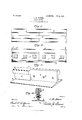
- Figure l is a top plan view showing the meeting ends of two rails united by my improved oint. F ig.
- Fig. 2 is a side elevation of the same.
- Fig. 3 is a perspective view of the end of one of the rail sections.
- Fig. 4 is a cross-section through the joint.
- the numerals 1i and 2 designate the meeting ends of two adjoining railway rails, each of which is generally of ordinary construction, to wit-provided with a base 3, a head 4 and a vertical inter-connecting web 5.
- each rail section has its head and -web cut away or omitted a desired distance inwardly from the end thereof to form a recess 6, which occupies one half of the width of the rail. lhen the two rail sections are arranged in proper relation for connection, these recesses aline with each other and form a space of requisite length to receive a joint-plate 7 which eX- tends across the joint or space between the ends of the rails and ,rests at its lower edge upon the base flanges 3 thereof.
- the plate is provided with a head-portion 8 which completes the formation of the treadsurface of the rail at the joint, thus providing a continuous tread across the joint over which the wheels of the rolling stock may pass without depressing the rail ends and causing the usual hammering, jolts and vibrations under which the meeting ends of the rails become quickly worn.
- the recessed portions of the rails and the joint plates are provided with registering transverse open ings 9 for the passage of the usual fastening bolts l0, whereby the parts of the joint are tied together.
- the joint plate when applied ⁇ in position lies wholly flush with the heads and sides of the rails on the side on which it is applied, and corresponds in every respect with the contour thereof, and that it is free from projections to secure it to the ties of the road-bed, being fastened solely to the meeting endsof the rail sections, and hence that the construction is such as to effectually prevent all liability of accidents from derailment of rolling stock caused by the engagement of the flanges of the wheels with offsetting projections, and also such as to permit of the use of the ordinary fish-plates in the usual manner to add strength and stability to the oints.
Landscapes
- Engineering & Computer Science (AREA)
- Mechanical Engineering (AREA)
- Architecture (AREA)
- Civil Engineering (AREA)
- Structural Engineering (AREA)
- Toys (AREA)
Description
No. 856,443.` PATBNTBDJUNB 11, 1907.
S. W. BOWSER.
RAIL JOINT.
APPLICATION FILED SEPT. B. 19064 Q erkannt SAMUEL WILSON BOWSER, OF JUNCTION CITY, OREGON.
RAIL-JOINT.
Speciiication of Letters Patent.
Patented June 11, 1907.
Application filed September 8,1906- Serial No. 333,861.
To @ZZ when?, t may concern;
Beit known that I, SAMUEL WILSON Bow- SER, a citizen o f the United States, residing at Junction City, in the county of Lane and State of Oregon, have invented new and useful Improvements in Rail-Joints, of which the following is a specification.
This invention relates to improvements in rail joints, the object of the invention being to provide a simple form of joint construction which will effectually obviate and prevent the hammering of the wheels in passing over the joint, thereby materially strengthening the joint as well as relieving the rails from a great proportion of the wear to which they are ordinarily subjected by the action of the Wheels, the parts of the joint also being so constructed as to permit, if desired, of the use of the usual lish-plates as elements of the joint connections.
In the accompanying drawings, Figure l is a top plan view showing the meeting ends of two rails united by my improved oint. F ig.
2 is a side elevation of the same. Fig. 3 is a perspective view of the end of one of the rail sections. Fig. 4 is a cross-section through the joint.
Referring to the drawings, the numerals 1i and 2 designate the meeting ends of two adjoining railway rails, each of which is generally of ordinary construction, to wit-provided with a base 3, a head 4 and a vertical inter-connecting web 5.
In accordance with my invention, each rail section has its head and -web cut away or omitted a desired distance inwardly from the end thereof to form a recess 6, which occupies one half of the width of the rail. lhen the two rail sections are arranged in proper relation for connection, these recesses aline with each other and form a space of requisite length to receive a joint-plate 7 which eX- tends across the joint or space between the ends of the rails and ,rests at its lower edge upon the base flanges 3 thereof.
The plate is provided with a head-portion 8 which completes the formation of the treadsurface of the rail at the joint, thus providing a continuous tread across the joint over which the wheels of the rolling stock may pass without depressing the rail ends and causing the usual hammering, jolts and vibrations under which the meeting ends of the rails become quickly worn. The recessed portions of the rails and the joint plates are provided with registering transverse open ings 9 for the passage of the usual fastening bolts l0, whereby the parts of the joint are tied together. These openings are made in practice of the usual form and of proper size to permit of the requisite amount of expansion and contraction of the rail sections under climatic changes.
It will be observed that the joint plate when applied `in position lies wholly flush with the heads and sides of the rails on the side on which it is applied, and corresponds in every respect with the contour thereof, and that it is free from projections to secure it to the ties of the road-bed, being fastened solely to the meeting endsof the rail sections, and hence that the construction is such as to effectually prevent all liability of accidents from derailment of rolling stock caused by the engagement of the flanges of the wheels with offsetting projections, and also such as to permit of the use of the ordinary fish-plates in the usual manner to add strength and stability to the oints.
Having thus described my invention, what I claim is z- In a rail oint, the combination of two rail sections of generally commercial form, said sections being provided at their meeting ends with recesses formed on one side thereof and occupying approximately one half of the thickness of each rail, each recess extending from the base through the head of the rail and being produced by the omission of one half of the head and web thereof, and a oint plate fitting in said recesses and completing the formation of the commercial shape across the joint, said plate having its outer surface lying flush with the sides of the rails, and suitable connections uniting the parts, substantially as described.
In testimony whereof, I aflix my signature in presence of two witnesses.
SAMUEL VILSON BOI/VSER.
I/Vitnesses:
P. T. STARR, W. S. MeFAnDnN.
Priority Applications (1)
| Application Number | Priority Date | Filing Date | Title |
|---|---|---|---|
| US33386106A US856443A (en) | 1906-09-08 | 1906-09-08 | Rail-joint. |
Applications Claiming Priority (1)
| Application Number | Priority Date | Filing Date | Title |
|---|---|---|---|
| US33386106A US856443A (en) | 1906-09-08 | 1906-09-08 | Rail-joint. |
Publications (1)
| Publication Number | Publication Date |
|---|---|
| US856443A true US856443A (en) | 1907-06-11 |
Family
ID=2924898
Family Applications (1)
| Application Number | Title | Priority Date | Filing Date |
|---|---|---|---|
| US33386106A Expired - Lifetime US856443A (en) | 1906-09-08 | 1906-09-08 | Rail-joint. |
Country Status (1)
| Country | Link |
|---|---|
| US (1) | US856443A (en) |
-
1906
- 1906-09-08 US US33386106A patent/US856443A/en not_active Expired - Lifetime
Similar Documents
| Publication | Publication Date | Title |
|---|---|---|
| US856443A (en) | Rail-joint. | |
| US883089A (en) | Rail-joint. | |
| US756962A (en) | Railroad joint and chair. | |
| US1013960A (en) | Metallic railroad. | |
| US898799A (en) | Rail-joint. | |
| US906796A (en) | Rail-joint. | |
| US795733A (en) | Rail-joint. | |
| US852206A (en) | Rail-joint chair. | |
| US841575A (en) | Rail-joint. | |
| US433273A (en) | Railroad-rail joint | |
| US904364A (en) | Rail-joint. | |
| US798358A (en) | Compound railroad-rail. | |
| US877340A (en) | Railway-crossing. | |
| US436572A (en) | James j | |
| US868494A (en) | Rail-joint. | |
| US205848A (en) | Improvement in railway-rail joints | |
| US527367A (en) | Railway-rail joint | |
| US1043645A (en) | Rail-joint. | |
| US830026A (en) | Railroad-track construction. | |
| US923876A (en) | Railroad-rail joint. | |
| US934720A (en) | Rail-joint. | |
| US966052A (en) | Rail-joint. | |
| US663894A (en) | Rail-joint. | |
| US787607A (en) | Rail-joint. | |
| US1024450A (en) | Rail-joint. |