US856439A - Boat-lashing device. - Google Patents
Boat-lashing device. Download PDFInfo
- Publication number
- US856439A US856439A US30618006A US1906306180A US856439A US 856439 A US856439 A US 856439A US 30618006 A US30618006 A US 30618006A US 1906306180 A US1906306180 A US 1906306180A US 856439 A US856439 A US 856439A
- Authority
- US
- United States
- Prior art keywords
- boat
- lashing
- lever
- rods
- members
- Prior art date
- Legal status (The legal status is an assumption and is not a legal conclusion. Google has not performed a legal analysis and makes no representation as to the accuracy of the status listed.)
- Expired - Lifetime
Links
- 238000010276 construction Methods 0.000 description 4
- 238000004873 anchoring Methods 0.000 description 2
- 230000005484 gravity Effects 0.000 description 2
- 230000001105 regulatory effect Effects 0.000 description 2
- 206010028980 Neoplasm Diseases 0.000 description 1
- 201000011510 cancer Diseases 0.000 description 1
- 230000000694 effects Effects 0.000 description 1
Images
Classifications
-
- B—PERFORMING OPERATIONS; TRANSPORTING
- B63—SHIPS OR OTHER WATERBORNE VESSELS; RELATED EQUIPMENT
- B63B—SHIPS OR OTHER WATERBORNE VESSELS; EQUIPMENT FOR SHIPPING
- B63B23/00—Equipment for handling lifeboats or the like
- B63B23/02—Davits, i.e. devices having arms for lowering boats by cables or the like
- B63B23/18—Davits, i.e. devices having arms for lowering boats by cables or the like with arms pivoting on substantially vertical axes
Definitions
- the invention relates to improvements in boat lashing devices.
- the object of the present invention is to improve the construction of devices for holding life-boats in an upright position on the deck of a vessel, and to provide a simple, inexpensive and eliicient device to enable the four lashings of a life-boat to be simultaneously released without the aid of a knife, ax, or other tool.
- a further object of the invention is to provide a boat lashing device, which will not jam and become inoperative should the lifeboat shift its position through heavy seas.
- Another object of the invention is to provide a metallic boat lashing, which will not freeze or become inoperative in cold weather, and from which the parts will not become separated when the device is detached.
- the invention also has for its obj eet to pro- Vide a boat lashing which may be instantly released in event of an accident, and which will also be capable of effecting a great saving in time in unlashing and lashing boats during fire and boat drills.
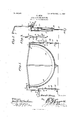
- Figure 1 is a transverse sectional view of a life-boat provided. with boat lashings constructed in accordance with this invention, one of the lashings being shown in its locked position, and the other lashing being released.
- Fig. 2 is a perspec- .trated in Fig.
- Fig. 3 is a longitudinal sectional view of the central portion of the boat lashing device.
- the upper member 1 designates an upper member of a boat lashing device, the said upper member being substantially in the form of a hook-shaped rod, and provided at its upper end. with a bill 2, for engaging the rail of a boat, the terminal 3 of the bill being bent downward to engage the inner edge of the rail, whereby the upper member 1 ol the boat lashing device is effectively prevented from accidentally slipping out of engagement with the boat.
- the lower portion 1 of the upper member is bifurcated, and is curved longitudinally to clear an upper pivot 5, which connects the inner end of a lever 6 with the lower member 7 of the boat lashing device.
- the lower member 7 is in the form of a turn-buckle,
- the lever 6 is pivoted at an intermediate point by a pin or rivet 8 to the lower member, and is adapted to be swung downward from the position illustrated at the left hand side of Fig. 1 of the drawing, to that shown at the right hand side of the said figure, whereby the upper and lower members of the boat lashing device are drawn together or moved longitudinally on each other. This causes the upper member to engage the rail of the boat, the strain on the boat being regulated by the turn-buckle.
- the lever is provided with a slight bend 9, which oflsets the outer or handle portion from the lower member of the boat lashing device, when the parts are in their locked position, as clearly illus- V 3 of the drawing. This construction arranges the handle in convenient position to enable it to be rcadil grasped, when it is desired to release the boat 10.
- the turn-buckle is composed of upper and lower sections 11 and 12, the upper section being provided. at its lower end with a nut 13 for engaging the lower section 12, which is in the form of a screw.
- the said upper section is composed of two side rods spaced apart to receive a screw, and connected at their lower ends by the said nut 13.
- the side rods of the upper section are also connected near their upper ends by a cross-piece 14, which maintains the side rods in their spaced relation.
- the upper ends oi the side rods of the upper section are provided with eyes to receive the pivot 5, and the cross-piece 14,
- the operating lever is locked in its position contiguous to the turn-buckle by means of a gravity locking device, consisting of a ring 17 arranged to encircle or embrace the upper portion of the turn-buckle and the upper portion of the operating lever when the parts are looked, as shown in Fig. 3.
- the cross-piece 14 serves as a stop for limiting the downward movement of the ring 17 and when it is desired to release the bolt, the ring is lifted above the turn-buckle and the lever is swung outwardly and upwardly. This disengages the upper member from the rail of the boat, and it will be apparent that the four boat lashing devices employed for holding a boat in an upright position on the deck of a vessel, may be simultaneously and instantly operated to release the boat.
- a distinctive feature of my invention is the permanent pivotal connection of the lever with the two members or sections, whereby the parts of the device are always connected together and there is no time lost in hunting for missing parts.
- a device of the class described comprising two members, one of which is provided with means for engaging a boat, means for anchoring the other member, an operating lever pivoted to each of the said members and thereby permanently connecting the same and adapted to draw the said members together to clamp a boat, and .means for locking the lever.
- a device of the class described comprising two members, one of which is provided with means for engaging a boat, means for anchoring the other member, an
- a device of the class described comprising two members, one of which is composed of two sections adjustable on each members for drawing the same together and ⁇ )or looking them in such position to clamp a oat.
- a device of the class described comprising an upper member having boat engaging means, a turn-buckle comprising a screw, and a section having a nut for engaging the screw and provided with spaced sides, and a lever pivoted at one end between the said sides and connected at an intermediate point with the upper member and adapted to swing downward between the said sides to cause the upper member to clamp a boat.
- a device of the class described comprising an upper member, a turn-buckle pro vided with spaced rods, a cross-piece connecting the rods at an intermediate point, a lever pivoted between the rods and connected with the upper member and arranged to swing downward between the rods, the movement of the lever being limited by the said cross-piece, and means for locking the lever contiguous to the cross-piece.
- a device of the class described com prising an upper member, a turnbuckle pro vided with spaced rods, a cross piece connecting the rods at an intermediate point, a lever pivoted between the rods and connected with the upper member and arranged to swing downward between the rods, the movement of the lever being limited by the said cross-piece, and a ring embracing the lever and the said rods and supported by the crosspiece.
Landscapes
- Chemical & Material Sciences (AREA)
- Engineering & Computer Science (AREA)
- Combustion & Propulsion (AREA)
- Mechanical Engineering (AREA)
- Ocean & Marine Engineering (AREA)
- Mutual Connection Of Rods And Tubes (AREA)
Description
No. 856,439. PATENTED JUNE 11, 1907.
H. BERG.
BOAT LASHING DEVICE.
APPLIUATION FILED MAR.15,1906.
@FFIGE.
HAROLD BERG, OF JACOBSVILLE, MICHIGAN.
BOAT-LASHING DEVICE.
Specification of Letters Patent.
Patented June 11, 1907.
Application filed March 15, 1906. Serial No- 306,180.
lb all whom itmag cancer/t:
Be it known that I, HAROLD BERG, a citizen of the United States, residing at Jacobsville, in the county of Houghton and State of Michigan, have invented certain new and useful Improvements in Boat-Lashing Devices, of which the following is a specification.
The invention relates to improvements in boat lashing devices.
The object of the present invention is to improve the construction of devices for holding life-boats in an upright position on the deck of a vessel, and to provide a simple, inexpensive and eliicient device to enable the four lashings of a life-boat to be simultaneously released without the aid of a knife, ax, or other tool.
A further object of the invention is to provide a boat lashing device, which will not jam and become inoperative should the lifeboat shift its position through heavy seas.
Another object of the invention is to provide a metallic boat lashing, which will not freeze or become inoperative in cold weather, and from which the parts will not become separated when the device is detached.
The invention also has for its obj eet to pro- Vide a boat lashing which may be instantly released in event of an accident, and which will also be capable of effecting a great saving in time in unlashing and lashing boats during fire and boat drills.
It is also the object of the invention to pro vide a boat lashing device which will be capable of longitudinal adjustment, to suit the size of the boat to be held and to regulate the strain on the same.
With these and other objects in view, the invention consists in the construction and novel combination and arrangement of parts, hereinafter fully described, illustrated in the accompanying drawings, and pointed. out in the claims, hereto appended; it being understood that various changes in the form, proportion, size and minor details of construction, within the scope of the claims, may be resorted to without departing from the spirit or sacrificing any of the advantages of the invention.
In the drawing :Figure 1 is a transverse sectional view of a life-boat provided. with boat lashings constructed in accordance with this invention, one of the lashings being shown in its locked position, and the other lashing being released. Fig. 2 is a perspec- .trated in Fig.
tive view of the boat lashing device detached. Fig. 3 is a longitudinal sectional view of the central portion of the boat lashing device.
Like numerals oi reference designate corresponding parts in all the figures oi the drawing.
1 designates an upper member of a boat lashing device, the said upper member being substantially in the form of a hook-shaped rod, and provided at its upper end. with a bill 2, for engaging the rail of a boat, the terminal 3 of the bill being bent downward to engage the inner edge of the rail, whereby the upper member 1 ol the boat lashing device is effectively prevented from accidentally slipping out of engagement with the boat. The lower portion 1 of the upper member is bifurcated, and is curved longitudinally to clear an upper pivot 5, which connects the inner end of a lever 6 with the lower member 7 of the boat lashing device. The lower member 7 is in the form of a turn-buckle,
and the lever 6 is pivoted at an intermediate point by a pin or rivet 8 to the lower member, and is adapted to be swung downward from the position illustrated at the left hand side of Fig. 1 of the drawing, to that shown at the right hand side of the said figure, whereby the upper and lower members of the boat lashing device are drawn together or moved longitudinally on each other. This causes the upper member to engage the rail of the boat, the strain on the boat being regulated by the turn-buckle. The lever is provided with a slight bend 9, which oflsets the outer or handle portion from the lower member of the boat lashing device, when the parts are in their locked position, as clearly illus- V 3 of the drawing. This construction arranges the handle in convenient position to enable it to be rcadil grasped, when it is desired to release the boat 10.
The turn-buckle is composed of upper and lower sections 11 and 12, the upper section being provided. at its lower end with a nut 13 for engaging the lower section 12, which is in the form of a screw. The said upper section is composed of two side rods spaced apart to receive a screw, and connected at their lower ends by the said nut 13. The side rods of the upper section are also connected near their upper ends by a cross-piece 14, which maintains the side rods in their spaced relation. The upper ends oi the side rods of the upper section are provided with eyes to receive the pivot 5, and the cross-piece 14,
which has terminal eyes for the reception of the side rods of the upper section, is bowed or bent between its ends to offset it from the operating lever, when the latter is in its locked position. The lower end of the screw 12 is provided with'a hook 15, for engaging an eye-bolt 16 in the deck of a vessel.
The operating lever is locked in its position contiguous to the turn-buckle by means of a gravity locking device, consisting of a ring 17 arranged to encircle or embrace the upper portion of the turn-buckle and the upper portion of the operating lever when the parts are looked, as shown in Fig. 3. The cross-piece 14; serves as a stop for limiting the downward movement of the ring 17 and when it is desired to release the bolt, the ring is lifted above the turn-buckle and the lever is swung outwardly and upwardly. This disengages the upper member from the rail of the boat, and it will be apparent that the four boat lashing devices employed for holding a boat in an upright position on the deck of a vessel, may be simultaneously and instantly operated to release the boat. Also it will be clear that should the boat shift its position through heavy seas, the boat lashings will not become jammed in any manner that will impair their operativeness. There is no liability of a boat becoming accidentally released, and it will be clear that the device will effect a great saving in time, both in lashing and unlashing a boat during fire and boat drills. The sections of the turn-buckle are adjustable to vary the length of the device to suit the size of a boat, and it will also enable the strain on a boat to be readily regulated.
A distinctive feature of my invention is the permanent pivotal connection of the lever with the two members or sections, whereby the parts of the device are always connected together and there is no time lost in hunting for missing parts.
Having thus fully described my invention, what I claim as new and desire to secure by Letters Patents, is
1. A device of the class described comprising two members, one of which is provided with means for engaging a boat, means for anchoring the other member, an operating lever pivoted to each of the said members and thereby permanently connecting the same and adapted to draw the said members together to clamp a boat, and .means for locking the lever.
2. A device of the class described comprising two members, one of which is provided with means for engaging a boat, means for anchoring the other member, an
operating lever pivoted at one end to one of the said members and also pivoted at an in termediate point to the other member and adapted to draw the members together to clamp a boat, and a gravity locking device for the said lever.
3. A device of the class described comprising two members, one of which is composed of two sections adjustable on each members for drawing the same together and {)or looking them in such position to clamp a oat.
5. A device of the class described comprising an upper member having boat engaging means, a turn-buckle comprising a screw, and a section having a nut for engaging the screw and provided with spaced sides, and a lever pivoted at one end between the said sides and connected at an intermediate point with the upper member and adapted to swing downward between the said sides to cause the upper member to clamp a boat.
6. A device of the class described comprising an upper member, a turn-buckle pro vided with spaced rods, a cross-piece connecting the rods at an intermediate point, a lever pivoted between the rods and connected with the upper member and arranged to swing downward between the rods, the movement of the lever being limited by the said cross-piece, and means for locking the lever contiguous to the cross-piece.
7. A device of the class described com prising an upper member, a turnbuckle pro vided with spaced rods, a cross piece connecting the rods at an intermediate point, a lever pivoted between the rods and connected with the upper member and arranged to swing downward between the rods, the movement of the lever being limited by the said cross-piece, and a ring embracing the lever and the said rods and supported by the crosspiece.
In testimony whereof I affiX my signature in presence of two witnesses.
HAROLD BERG.
TIO
Priority Applications (1)
| Application Number | Priority Date | Filing Date | Title |
|---|---|---|---|
| US30618006A US856439A (en) | 1906-03-15 | 1906-03-15 | Boat-lashing device. |
Applications Claiming Priority (1)
| Application Number | Priority Date | Filing Date | Title |
|---|---|---|---|
| US30618006A US856439A (en) | 1906-03-15 | 1906-03-15 | Boat-lashing device. |
Publications (1)
| Publication Number | Publication Date |
|---|---|
| US856439A true US856439A (en) | 1907-06-11 |
Family
ID=2924894
Family Applications (1)
| Application Number | Title | Priority Date | Filing Date |
|---|---|---|---|
| US30618006A Expired - Lifetime US856439A (en) | 1906-03-15 | 1906-03-15 | Boat-lashing device. |
Country Status (1)
| Country | Link |
|---|---|
| US (1) | US856439A (en) |
-
1906
- 1906-03-15 US US30618006A patent/US856439A/en not_active Expired - Lifetime
Similar Documents
| Publication | Publication Date | Title |
|---|---|---|
| US3861731A (en) | Boat handler | |
| US1536701A (en) | Device for mooring ships and the like | |
| US2161906A (en) | Marine anchor | |
| US856439A (en) | Boat-lashing device. | |
| RU2019142425A (en) | DEVICE INSURANCE STRAP FOR CARGO TRANSPORTATION | |
| US2313802A (en) | Safety raft slip lock | |
| US751359A (en) | Car-loader | |
| US1101113A (en) | Hook for life-boats and the like. | |
| US926453A (en) | Means for automatically releasing ships' boats. | |
| US869130A (en) | Yielding boat-cleat. | |
| US761809A (en) | Detaching device for life-boats. | |
| US805631A (en) | Clamp. | |
| US838286A (en) | Hawse-pipe cover and anchor-clamp. | |
| US674865A (en) | Hitching device. | |
| US431741A (en) | Device for suspending boats in davits on vessels | |
| US898094A (en) | Boat-lashing device. | |
| US1174786A (en) | Combination hog hook and gambrel. | |
| US481782A (en) | Anchor | |
| US819022A (en) | Boat holding-down and detaching device. | |
| US1071048A (en) | Block-hook. | |
| US284431A (en) | Charles johnson | |
| US355983A (en) | Thomas emerson | |
| US249334A (en) | Rope-fastener | |
| US443473A (en) | Grab-hook | |
| US780520A (en) | Tackle-block. |