US856413A - Grab. - Google Patents
Grab. Download PDFInfo
- Publication number
- US856413A US856413A US34167606A US1906341676A US856413A US 856413 A US856413 A US 856413A US 34167606 A US34167606 A US 34167606A US 1906341676 A US1906341676 A US 1906341676A US 856413 A US856413 A US 856413A
- Authority
- US
- United States
- Prior art keywords
- closing
- sheave
- grab
- shells
- sheaves
- Prior art date
- Legal status (The legal status is an assumption and is not a legal conclusion. Google has not performed a legal analysis and makes no representation as to the accuracy of the status listed.)
- Expired - Lifetime
Links
Images

Classifications
-
- B—PERFORMING OPERATIONS; TRANSPORTING
- B66—HOISTING; LIFTING; HAULING
- B66C—CRANES; LOAD-ENGAGING ELEMENTS OR DEVICES FOR CRANES, CAPSTANS, WINCHES, OR TACKLES
- B66C3/00—Load-engaging elements or devices attached to lifting or lowering gear of cranes or adapted for connection therewith and intended primarily for transmitting lifting forces to loose materials; Grabs
- B66C3/12—Grabs actuated by two or more ropes
Definitions
- ARCHIBALD G MONKS, OF BROOKLINE, MASSACHUSETTS.
- My invention relates to grabs or hoisting buckets, and its principal objects are to provide a grab or bucket in which the parts shall not be subjected to any lateral strain or twist when the power is applied to the holding and the closing falls; to organize and ar-I range the closing sheaves and fall so that the lines of force shall be distributed and directed to the best advantage when the closing fall is operated; and to improve the construction of the top head of the grab in such a way as to protect the .holding fall from injury, and otherwise to improve the balance and strength of the top head and the parts depending therefrom.
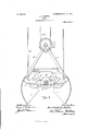
- Figure 1 is a side elevation of a grab containing my invention, the shells of thegrab being in closed position; Fig.
- Fig. 2 is a vertical section of said grab through the middle of Fig. 1, s onie ofthe parts being shown in elevation;
- Fig. 3 is a side elevation of the grab shown in Fig. 1, the shells being in open position;
- Fig. 4 is a detail showing in vertical longitudinal section the holding sheave, holding fall and keeper;
- Fig. 5 is a detail showing in vertical eross section one of the closing sheaves and its keeper.
- 1, 1 represent the pair of separable sections or shells of the grab. Pivotally connected with the outer corners of each shell 1, 1 are the supporting arms 2, 2 which converge toward their tops as shown and are pivoted at the top upon the top head shaft 3.
- the arms 2 are pivotally attached to the shells 1, 1 by any suitable means, as by the forked lugs 4, 4.
- Rigidly secured to the shells 1, 1 are the forked closing levers 5, 5 which extend upward from the shells of the grab at acute angles and are journaled upon the shaft 6, at which point the lever 5 of one shell crosses-the lever 5 of the other shell as shown, the hubs 7, 7 furnishing suitable bearings.
- Additional arms or braces 8, 8 are provided', also journaled upon shaft 6 as shown.
- the closing sheaves 9, 9 are journaled; these sheaves are preferably inclosed in keepers 10 to prevent the closing cable or fall from coming out of engagement with the sheaves.
- Midway between the closing levers 5, 5 is j ouriialed the sheave 11, the purpose and operation of which will presently be described.
- the top head of the grae comprises the top head shaft 3 (from which depend the shells of the bucket and the operating parts all supported by the arms 2, 2), the holding sheave 12 mounted on the top head shaft 3, the keeper 13, and a guard projecting above sheave 12 to act as a buffer te prevent the shea ve 12 from injury when the grab is hoisted up to the boom or trolley from which the grab is suspended.
- This guard preferably consists of a pair of disks 14, 141 mounted to rotate idly on the top head shaft 3, one on either side of the holding sheave 12.
- the holding fall 15 passes under sheave 12 I and is secured to the trolley or boom above, with provision for lengthening or shortening it to lower or raise the grab, all in any well known manner ⁇
- the closing fall 16 passes under the two closing sheaves 9, 9 and above the sheave 11.
- the closing fall also is secured to the boom or trolley with provision for operating it in any well known manner. Both the holding and the closing falls maybe cables or chains as desired.
- FIG. 3 shows the grab in open position. It will be observed that when the grab is closed the closing fall 16 is out of contact- IOO IIO
- guards in the top head than the disks 14, 14 may be employed and are within the scope of my invention, I believe that the form above described possesses advantages not possessed by other forms.
- the guard pieces rotatably mounted on the top head shaft 3 instead of rigidly secured, ⁇ they will immediately roll into their proper position when the rab is hoisted up into contact with the tro ley or ⁇ boom whether it be hoisted vertically, in a straight line, or swinging.
- the guards are rigidly held'against the trolley or boom, they will permit the grab to swing freely.
- the guard disks 14, 14 may be mounted to rotate idly upon the top head shaft as shown in the drawings, or they may, if desired, bebolted or otherwise secured to the holding sheave. Either form is within the scope of my invention and is contem-a plated by the claims.
- a grab comprising the pair of separable shells, a pair of closing levers crossed and pivotally connected together, each secured at its 'lower end to one of the shells and provided at its upper end with a closing sheave, a sheave mounted at the axis of the closing levers, and a closing fall passing under the closing sheaves and above the sheave at the Y axis of the levers.
- a pair of closing levers crossed and pivotally connected together each secured at its lower end to one of the shells and provided at its upper end with a closing sheave, a sheave mounted at the axis of the closing levers, and a closing fall passing under the closing sheaves and above the sheave at the axis of the levers, all of said sheaves being in-the same plane.
- a grab comprising a pair of separable shells, a holding sheave, supporting arms between the axis of the holding sheave and the outer corners of the shells, a pair of closing levers crossed .and pivotally connected together, eachsecured at its lower end to one of the shells and provided at its upper end with a closing sheave, and a closing fall passing under the closing sheaves, all of said sheaves being in the same'plane.
- a grab comprising a pair of separable shells, a holding sheave, supporting arms connecting the holding sheave and theshells, a pair of closing levers crossed and pivotally connected together, each secured at its lower end to one of the shells, and provided at its upper end with a closing sheave, a sheave mounted at the axis of the operating levers, and a closing fall passing under the closing sheaves and above the sheave at the axis of levers, the parts being organized and arranged so that the closing fall between the closing sheaves will not be deflected by the sheave at the axis of the levers' when the grab is closed., but will be deiiected thereby when the grab is open.
- a top head comprising a top head shaft, supportin arms pivotally connected therewith, a ho ding'sheave mounted on the top head shaft and a guard upon said top head shalt projecting above the sheave and adapted to act as a buffer when the grab is hoisted.
- a top head comprising a top head shaft, supportin arms pivotally connected therewith, a ho ding sheave mounted on the top head shaft, and a guard rotatably mounted upon said top head shaft, projecting above t e sheave, and ada ted to act as a buffer when the grab is hoiste 8.
- a top head comprising a top head shaft, supporting arms pivotally connected therewith, a holding sheave mounted on the top head shaft, and a guard consisting of a pair of disks, one mounted on either side of the sheave, and having a'greater diameter than the sheave.
- a grab comprising a pair of separable shells, a holding sheave, supporting arms between the axis of the holding sheave and the outer corners of the shells, a pair of forked closing levers crossed and pivotally connected together, each rigidly secured at its lower end to one of the shells and provided at its upper end witha closing sheave, a sheave TOO IIO
Description
PATENTED 111111111, 1907.
A. G. MONKS.
GRAB.
APPLIoATloN FILED Nov.2.1ooe.
2 SHEETS-SHEET 1.
lli/y mul?? 1H: NDRRJs Pzrrns cm, wAsmNaraN. n. c.
PATBNTED JUNE 11. 1907.
A. G. MGNKS.
GRAB.
APPLIOATION FILED Nov. 2,1906.
2 SHEETS-SHEET 2.
2622/695565 13m/926% r.' @WM wafww and@ ffdc@ fue wams PErcRs cn.. wAsulncfoN, n. c
ARCHIBALD G. MONKS, OF BROOKLINE, MASSACHUSETTS.
GRAB.
Specification of Letters Patent.
Patented June 11, 1907.
Application filed November 2, 1906. Serial No. 341,6 76.
To all whom it may concern,.-
Be it known that I, ARCHIBALD G. MONKs, a citizen ofthe United States, and a resident of Brookline, in the county of Norfolk and State of Massachusetts, have invented new and useful Improvements in lGrabs, of which the following is a specification.
My invention relates to grabs or hoisting buckets, and its principal objects are to provide a grab or bucket in which the parts shall not be subjected to any lateral strain or twist when the power is applied to the holding and the closing falls; to organize and ar-I range the closing sheaves and fall so that the lines of force shall be distributed and directed to the best advantage when the closing fall is operated; and to improve the construction of the top head of the grab in such a way as to protect the .holding fall from injury, and otherwise to improve the balance and strength of the top head and the parts depending therefrom. Other features will be hereinafter described. In the accompanying drawings which illustrate one embodiment of my invention, Figure 1 is a side elevation of a grab containing my invention, the shells of thegrab being in closed position; Fig. 2 is a vertical section of said grab through the middle of Fig. 1, s onie ofthe parts being shown in elevation; Fig. 3 is a side elevation of the grab shown in Fig. 1, the shells being in open position; Fig. 4 is a detail showing in vertical longitudinal section the holding sheave, holding fall and keeper; and Fig. 5 is a detail showing in vertical eross section one of the closing sheaves and its keeper.
The saine parts are indicated by like reference numerals in all of the figures.
Referring to the drawings, 1, 1 represent the pair of separable sections or shells of the grab. Pivotally connected with the outer corners of each shell 1, 1 are the supporting arms 2, 2 which converge toward their tops as shown and are pivoted at the top upon the top head shaft 3. The arms 2 are pivotally attached to the shells 1, 1 by any suitable means, as by the forked lugs 4, 4. Rigidly secured to the shells 1, 1 are the forked closing levers 5, 5 which extend upward from the shells of the grab at acute angles and are journaled upon the shaft 6, at which point the lever 5 of one shell crosses-the lever 5 of the other shell as shown, the hubs 7, 7 furnishing suitable bearings. Additional arms or braces 8, 8 are provided', also journaled upon shaft 6 as shown. At the upper ends of lever arms 5, 5 the closing sheaves 9, 9 are journaled; these sheaves are preferably inclosed in keepers 10 to prevent the closing cable or fall from coming out of engagement with the sheaves. Midway between the closing levers 5, 5 is j ouriialed the sheave 11, the purpose and operation of which will presently be described.
The top head of the grae comprises the top head shaft 3 (from which depend the shells of the bucket and the operating parts all supported by the arms 2, 2), the holding sheave 12 mounted on the top head shaft 3, the keeper 13, and a guard projecting above sheave 12 to act as a buffer te prevent the shea ve 12 from injury when the grab is hoisted up to the boom or trolley from which the grab is suspended. This guard preferably consists of a pair of disks 14, 141 mounted to rotate idly on the top head shaft 3, one on either side of the holding sheave 12.
The holding fall 15 passes under sheave 12 I and is secured to the trolley or boom above, with provision for lengthening or shortening it to lower or raise the grab, all in any well known manner` The closing fall 16 passes under the two closing sheaves 9, 9 and above the sheave 11. The closing fall also is secured to the boom or trolley with provision for operating it in any well known manner. Both the holding and the closing falls maybe cables or chains as desired.
The operation of the device is as follows: In the position shown in Fig. 1 in which the shells ofthe grab are closed, the closing fall 16 is taut, tending to pull the closing sheaves upward and together and thus to hold the shells together. When the tension on the closing fall is slackened the grab will open by gravity,
the weight of the shells, the closing levers and other parts tending to spread the two sections apart. Fig. 3 shows the grab in open position. It will be observed that when the grab is closed the closing fall 16 is out of contact- IOO IIO
close the shells together, but the tendency of the stretch of fall 16 between sheaves 9, 9 is to straighten out under tension, thus forcing sheave ll and its axis, which is also the axis of the closing levers, downward at the same time the sheaves 9, 9 are forced upward, whereby the closing power of the grab is greatly increased over that of grabs heretofore used lacking the sheave 11. It will also be observed that all of the sheaves 9, 9 ll and l2 are in the same plane, or in alinement. In other hoisting buckets so far as I am aware, the hoisting sheave and the closing sheaves have not been in the same plane but have been offset, one with relation to the other, with the result that the supporting bars 2, 2 the top head shaft 3, and other parts of the grab have been subjected to a lateral strain or twist and have frequently broken. This tendency is avoided in the improved grab above described, and the strength and durability of the device is consequently increased.
W'hile other forms of guards in the top head than the disks 14, 14 may be employed and are within the scope of my invention, I believe that the form above described possesses advantages not possessed by other forms. By having the guard pieces rotatably mounted on the top head shaft 3 instead of rigidly secured,` they will immediately roll into their proper position when the rab is hoisted up into contact with the tro ley or` boom whether it be hoisted vertically, in a straight line, or swinging. Moreover, even when the guards are rigidly held'against the trolley or boom, they will permit the grab to swing freely. The guard disks 14, 14 may be mounted to rotate idly upon the top head shaft as shown in the drawings, or they may, if desired, bebolted or otherwise secured to the holding sheave. Either form is within the scope of my invention and is contem-a plated by the claims.
I claim: l. A grab comprising the pair of separable shells, a pair of closing levers crossed and pivotally connected together, each secured at its 'lower end to one of the shells and provided at its upper end with a closing sheave, a sheave mounted at the axis of the closing levers, and a closing fall passing under the closing sheaves and above the sheave at the Y axis of the levers.
necting the holding sheave and the shells, a pair of closing levers crossed and pivotally connected together, each secured at its lower end to one of the shells and provided at its upper end with a closing sheave, a sheave mounted at the axis of the closing levers, and a closing fall passing under the closing sheaves and above the sheave at the axis of the levers, all of said sheaves being in-the same plane.
4. A grab comprising a pair of separable shells, a holding sheave, supporting arms between the axis of the holding sheave and the outer corners of the shells, a pair of closing levers crossed .and pivotally connected together, eachsecured at its lower end to one of the shells and provided at its upper end with a closing sheave, and a closing fall passing under the closing sheaves, all of said sheaves being in the same'plane.
5. A grab comprising a pair of separable shells, a holding sheave, supporting arms connecting the holding sheave and theshells, a pair of closing levers crossed and pivotally connected together, each secured at its lower end to one of the shells, and provided at its upper end with a closing sheave, a sheave mounted at the axis of the operating levers, and a closing fall passing under the closing sheaves and above the sheave at the axis of levers, the parts being organized and arranged so that the closing fall between the closing sheaves will not be deflected by the sheave at the axis of the levers' when the grab is closed., but will be deiiected thereby when the grab is open.
V6. In a grab, a top head comprising a top head shaft, supportin arms pivotally connected therewith, a ho ding'sheave mounted on the top head shaft and a guard upon said top head shalt projecting above the sheave and adapted to act as a buffer when the grab is hoisted.
7. In a grab, a top head comprising a top head shaft, supportin arms pivotally connected therewith, a ho ding sheave mounted on the top head shaft, and a guard rotatably mounted upon said top head shaft, projecting above t e sheave, and ada ted to act as a buffer when the grab is hoiste 8. In a grab, a top head comprising a top head shaft, supporting arms pivotally connected therewith, a holding sheave mounted on the top head shaft, and a guard consisting of a pair of disks, one mounted on either side of the sheave, and having a'greater diameter than the sheave.
9. A grab comprising a pair of separable shells, a holding sheave, supporting arms between the axis of the holding sheave and the outer corners of the shells, a pair of forked closing levers crossed and pivotally connected together, each rigidly secured at its lower end to one of the shells and provided at its upper end witha closing sheave, a sheave TOO IIO
mounted at the axis of the closing levers, a Signed by me at Boston, Massachusetts, closing fall passing under the closing sheaves this twenty ninth day of October, 1906. and above the sheave at the axis of the levers, all of said sheaves being? in the saine ARCHIBALD G MONKS plane, and a pair of guard disks rotatably l/Vitnesses: mounted one on either side of the holding ODINv ROBERTS,
sheave, substantially as described. B. DEVEREUX BARKER.
Priority Applications (1)
| Application Number | Priority Date | Filing Date | Title |
|---|---|---|---|
| US34167606A US856413A (en) | 1906-11-02 | 1906-11-02 | Grab. |
Applications Claiming Priority (1)
| Application Number | Priority Date | Filing Date | Title |
|---|---|---|---|
| US34167606A US856413A (en) | 1906-11-02 | 1906-11-02 | Grab. |
Publications (1)
| Publication Number | Publication Date |
|---|---|
| US856413A true US856413A (en) | 1907-06-11 |
Family
ID=2924868
Family Applications (1)
| Application Number | Title | Priority Date | Filing Date |
|---|---|---|---|
| US34167606A Expired - Lifetime US856413A (en) | 1906-11-02 | 1906-11-02 | Grab. |
Country Status (1)
| Country | Link |
|---|---|
| US (1) | US856413A (en) |
-
1906
- 1906-11-02 US US34167606A patent/US856413A/en not_active Expired - Lifetime
Similar Documents
| Publication | Publication Date | Title |
|---|---|---|
| US856413A (en) | Grab. | |
| US987418A (en) | Freight-hoist. | |
| US321159A (en) | thompson | |
| US870812A (en) | Grab-bucket and operating mechanism. | |
| US183543A (en) | Improvement in dredging-machines | |
| US426681A (en) | Dredging-machine | |
| US1093832A (en) | Grapple. | |
| US1043323A (en) | Safety appliance for pit cages, lifts, and the like. | |
| US1382327A (en) | Wide-opening clam-shell bucket | |
| US497021A (en) | George i-iaiss | |
| US808493A (en) | Means for turning hoisting-buckets. | |
| US255351A (en) | Hoisting apparatus | |
| US1202681A (en) | Hoisting-fork. | |
| US742763A (en) | Gate. | |
| US676189A (en) | Clam-shell bucket. | |
| US571303A (en) | Coal-bucket | |
| US381258A (en) | Manlet c | |
| US1129356A (en) | Rock-grab. | |
| US659100A (en) | Hoisting-grip. | |
| US553256A (en) | notter | |
| US600061A (en) | Chusetts | |
| US238293A (en) | johnson | |
| US1090067A (en) | Derrick. | |
| US730280A (en) | Ore or dredging bucket. | |
| US861669A (en) | Clam-shell bucket. |