US856200A - Adjustable colter-clamp. - Google Patents
Adjustable colter-clamp. Download PDFInfo
- Publication number
- US856200A US856200A US34617206A US1906346172A US856200A US 856200 A US856200 A US 856200A US 34617206 A US34617206 A US 34617206A US 1906346172 A US1906346172 A US 1906346172A US 856200 A US856200 A US 856200A
- Authority
- US
- United States
- Prior art keywords
- clamp
- colter
- standard
- members
- bar
- Prior art date
- Legal status (The legal status is an assumption and is not a legal conclusion. Google has not performed a legal analysis and makes no representation as to the accuracy of the status listed.)
- Expired - Lifetime
Links
- 238000010276 construction Methods 0.000 description 6
- NAXKFVIRJICPAO-LHNWDKRHSA-N [(1R,3S,4R,6R,7R,9S,10S,12R,13S,15S,16R,18S,19S,21S,22S,24S,25S,27S,28R,30R,31R,33S,34S,36R,37R,39R,40S,42R,44R,46S,48S,50R,52S,54S,56S)-46,48,50,52,54,56-hexakis(hydroxymethyl)-2,8,14,20,26,32,38,43,45,47,49,51,53,55-tetradecaoxa-5,11,17,23,29,35,41-heptathiapentadecacyclo[37.3.2.23,7.29,13.215,19.221,25.227,31.233,37.04,6.010,12.016,18.022,24.028,30.034,36.040,42]hexapentacontan-44-yl]methanol Chemical compound OC[C@H]1O[C@H]2O[C@H]3[C@H](CO)O[C@H](O[C@H]4[C@H](CO)O[C@H](O[C@@H]5[C@@H](CO)O[C@H](O[C@H]6[C@H](CO)O[C@H](O[C@H]7[C@H](CO)O[C@@H](O[C@H]8[C@H](CO)O[C@@H](O[C@@H]1[C@@H]1S[C@@H]21)[C@@H]1S[C@H]81)[C@H]1S[C@@H]71)[C@H]1S[C@H]61)[C@H]1S[C@@H]51)[C@H]1S[C@@H]41)[C@H]1S[C@H]31 NAXKFVIRJICPAO-LHNWDKRHSA-N 0.000 description 4
- XEEYBQQBJWHFJM-UHFFFAOYSA-N Iron Chemical compound [Fe] XEEYBQQBJWHFJM-UHFFFAOYSA-N 0.000 description 2
- 229910000831 Steel Inorganic materials 0.000 description 1
- 238000005266 casting Methods 0.000 description 1
- 238000007689 inspection Methods 0.000 description 1
- 229910052742 iron Inorganic materials 0.000 description 1
- 239000010959 steel Substances 0.000 description 1
- 239000002023 wood Substances 0.000 description 1
Images
Classifications
-
- F—MECHANICAL ENGINEERING; LIGHTING; HEATING; WEAPONS; BLASTING
- F16—ENGINEERING ELEMENTS AND UNITS; GENERAL MEASURES FOR PRODUCING AND MAINTAINING EFFECTIVE FUNCTIONING OF MACHINES OR INSTALLATIONS; THERMAL INSULATION IN GENERAL
- F16B—DEVICES FOR FASTENING OR SECURING CONSTRUCTIONAL ELEMENTS OR MACHINE PARTS TOGETHER, e.g. NAILS, BOLTS, CIRCLIPS, CLAMPS, CLIPS OR WEDGES; JOINTS OR JOINTING
- F16B7/00—Connections of rods or tubes, e.g. of non-circular section, mutually, including resilient connections
-
- F—MECHANICAL ENGINEERING; LIGHTING; HEATING; WEAPONS; BLASTING
- F16—ENGINEERING ELEMENTS AND UNITS; GENERAL MEASURES FOR PRODUCING AND MAINTAINING EFFECTIVE FUNCTIONING OF MACHINES OR INSTALLATIONS; THERMAL INSULATION IN GENERAL
- F16B—DEVICES FOR FASTENING OR SECURING CONSTRUCTIONAL ELEMENTS OR MACHINE PARTS TOGETHER, e.g. NAILS, BOLTS, CIRCLIPS, CLAMPS, CLIPS OR WEDGES; JOINTS OR JOINTING
- F16B2/00—Friction-grip releasable fastenings
- F16B2/02—Clamps, i.e. with gripping action effected by positive means other than the inherent resistance to deformation of the material of the fastening
- F16B2/06—Clamps, i.e. with gripping action effected by positive means other than the inherent resistance to deformation of the material of the fastening external, i.e. with contracting action
- F16B2/065—Clamps, i.e. with gripping action effected by positive means other than the inherent resistance to deformation of the material of the fastening external, i.e. with contracting action using screw-thread elements
-
- E—FIXED CONSTRUCTIONS
- E04—BUILDING
- E04B—GENERAL BUILDING CONSTRUCTIONS; WALLS, e.g. PARTITIONS; ROOFS; FLOORS; CEILINGS; INSULATION OR OTHER PROTECTION OF BUILDINGS
- E04B1/00—Constructions in general; Structures which are not restricted either to walls, e.g. partitions, or floors or ceilings or roofs
- E04B1/18—Structures comprising elongated load-supporting parts, e.g. columns, girders, skeletons
- E04B1/24—Structures comprising elongated load-supporting parts, e.g. columns, girders, skeletons the supporting parts consisting of metal
- E04B1/2403—Connection details of the elongated load-supporting parts
-
- F—MECHANICAL ENGINEERING; LIGHTING; HEATING; WEAPONS; BLASTING
- F16—ENGINEERING ELEMENTS AND UNITS; GENERAL MEASURES FOR PRODUCING AND MAINTAINING EFFECTIVE FUNCTIONING OF MACHINES OR INSTALLATIONS; THERMAL INSULATION IN GENERAL
- F16B—DEVICES FOR FASTENING OR SECURING CONSTRUCTIONAL ELEMENTS OR MACHINE PARTS TOGETHER, e.g. NAILS, BOLTS, CIRCLIPS, CLAMPS, CLIPS OR WEDGES; JOINTS OR JOINTING
- F16B7/00—Connections of rods or tubes, e.g. of non-circular section, mutually, including resilient connections
- F16B7/04—Clamping or clipping connections
- F16B7/044—Clamping or clipping connections for rods or tubes being in angled relationship
- F16B7/048—Clamping or clipping connections for rods or tubes being in angled relationship for rods or for tubes without using the innerside thereof
- F16B7/0493—Clamping or clipping connections for rods or tubes being in angled relationship for rods or for tubes without using the innerside thereof forming a crossed-over connection
Definitions
- Our invention is an improved adjustable colter clamp, by means of which the standard of a colter may be securely fastened to a plow beam of any construction, and may be adjusted as may be desired, and it consists in the construction, combination, and arrangement of devices hereinafter described and claimed.
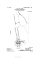
- FIG. 1 is partly a side elevation andpartly a longitudinal sectional view of a colter clamp embodying our improvements, showing the same in operative relation to the beam of a plow and the standard of a colter;
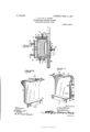
- Fig. 2 is a transverse sectional view of the same;
- Figs. 3 and 4 are detail perspective views of the respective members of the clamp;
- Fig. 5 is a perspective view, showing the outer side of the clamp member 2;
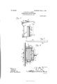
- Fig. 6 is a transverse sectional view of our improved colter clamp, showing the same in operative relation to the beam of a plow and the cylindrical standard of a colter.
- Fig. 7 is a detail elevation of the wedge block.
- Our improved colter clamp comprises two members 1, 2, ⁇ adapted to be placed on opposite sides of a plow beam, such as indicated at a, or of any other construction, and secured thereto by bolts 3, 4.
- The. section 1, which in practice is a casting, is provided at its upper side with a lateral bar 5 to extend above the beam and has at its lower end a lateral bar 6 to bear against the lower side of the beam and provided with a depending ange 7.
- the bar 5 has a transverse dovetail slot 8 which is open at one end,
- an outwardly-projecting portion 9 On the outer side of the member l is an outwardly-projecting portion 9, provided with a vertical slot 10 eX- tending therethrough from its upper to its lower side, said slot being of such size as to enable it to receive the standard b of a colter and permit said standard to be disposed either in a vertical position or in an inclined position.
- a screw-threaded opening 11 in which is a set-screw 12 to bear against the other side of the standard l) and clamp the same in place.
- the section 2 has at its upper end a laterally-extending bar 15 to extend above the plow beam and has at its lower end a bar 16 to bear against the lower side of the plow beam and provided with a flange 17.
- the bolts l are placed in openings in the flanges 7 and 17, and the bolts 3 are placed in openings at the upper ends of the member 1, 2, said bolts 3, 4, as hereinbefore stated, serving to clamp said members to opposite sides of the plow beam.
- the bar 15 of the clamp member 2 has on its upper side a dovetail shoulder 18 to enter and it in the dovetail slot 8 of the bar 5 of the member l. It will be understood from the inspection of Fig.
- wedge block 19 which is inserted between the upper edge of the plow beam and the lateral bar 15 of the clamp member 2, to fill the space between the beam and said bar and adapt the clamp to be attached to beams which vary in width vertically.
- the said wedge block has a series of depressions or seats 2O in the upper side for the reception of the lower end of a setscrew 21, which operates in a threaded opening in the bar 15 of the member 2.
- serrations 22 On the under side of the said wedge block are transverse, serrations 22 to engage the upper side of the beam and insure a firm grip between the wedge block and the beam.
- the clamp member 2 with an outwardly-extending, vertically-disposed portion 23 on its outer side, provided with a vertical, cylindrical slot 24 IOO IIO
- Said portion 23 is provided with set-screws 25 to clamp the said standard.
- a colter clamp of the class described comprising a pair of members to engage opposite sides of a beam and provided with overlapping bars, one of said 'bars having a transverse slot and the other having a transverse shoulder to engage said slot, means to adj ustably secure said members together and clamp them on opposite sides of the beam, one of said members having means, independent of the said securing and clamping means, to adjustably secure a colter standard to said member.
- a colter clamp of the class described comprising a pair of members to engage opposite sides of a beam, one of said members having a vertical opening to receive the standard of a colter, and further provided with means to receive said standard at any desired adjustment, and means independent of said standard receiving means, to clamp the said members on opposite sides of the beam.
Description
PATENTED AJULIEN.' 1.907'.- J. H. @L R. LLALLIN. ADJUSTABLE GOLTBR CLAMP.
APPLICATION FILED DEO. 3,1906.
3 SHEETS-SHEET 1.
SUMit/w15@ WW1/meow ry: Nafmls PETER/s co., WASHINGTON, n.1;
PATENTED JUNE 11, 1907.
a.. T E E H s T E E H s 3 P.. Mw mmm m03. ,Mmm .wb-*M 8 l F REN &Lm .BT Hmm ZJ: A...LSL .MA .A
. PATENT-ED JUNE 1l, 1907. J. H. Rv. L. ALLIN. ADJUSTABLE COLTEB. CLAMP.
APPLICATION FILED DEc.s.19os.
lL. ///Q I4/wanton @wi/knees@ U-,WASHINGTON D.
UNITED STATES PATENT OFFICE..
JOSEPH H. ALLIN AND ROBERT L. ALLIN, OF PEOAN GAP, TEXAS.
ADJUSTABLE COLTER-CLAIVlP.
Specification of Letters Patent.
Patented June 11, 1907.
Application led December 3,1906. Serial No. 346,172.
T0 all whom, it 71mg/ concern:
Be it known that we, JOSEPH H. ALLIN and ROBERT L. ALLiN, `citizens of the United States, residing at Pecan Gap, in the county of Delta and State of Texas, have invented certain new and useful Improvements in Adjustable Colter-Olamps; and we do declare the following to be a full, clear, and eX- act description of the invention, such as will enable others skilled in the art to which it appertains to make and use the same.
Our invention is an improved adjustable colter clamp, by means of which the standard of a colter may be securely fastened to a plow beam of any construction, and may be adjusted as may be desired, and it consists in the construction, combination, and arrangement of devices hereinafter described and claimed.
In the accompanying drawings,-Figure 1 is partly a side elevation andpartly a longitudinal sectional view of a colter clamp embodying our improvements, showing the same in operative relation to the beam of a plow and the standard of a colter; Fig. 2 is a transverse sectional view of the same; Figs. 3 and 4 are detail perspective views of the respective members of the clamp; Fig. 5 is a perspective view, showing the outer side of the clamp member 2; and Fig. 6 is a transverse sectional view of our improved colter clamp, showing the same in operative relation to the beam of a plow and the cylindrical standard of a colter. Fig. 7 is a detail elevation of the wedge block.
Our improved colter clamp comprises two members 1, 2,` adapted to be placed on opposite sides of a plow beam, such as indicated at a, or of any other construction, and secured thereto by bolts 3, 4. The. section 1, which in practice is a casting, is provided at its upper side with a lateral bar 5 to extend above the beam and has at its lower end a lateral bar 6 to bear against the lower side of the beam and provided with a depending ange 7. The bar 5 has a transverse dovetail slot 8 which is open at one end, On the outer side of the member l is an outwardly-projecting portion 9, provided with a vertical slot 10 eX- tending therethrough from its upper to its lower side, said slot being of such size as to enable it to receive the standard b of a colter and permit said standard to be disposed either in a vertical position or in an inclined position. In the outer side of the projecting portion 9 at the center thereof, is a screw-threaded opening 11, in which is a set-screw 12 to bear against the other side of the standard l) and clamp the same in place. In the front and rear sides of the said projecting portion 9 are similar openings 13 to receive screws 14, the said screws bearing against the front and rear edges of the colter and serving in connection with the screw 12 to securely hold the colter either in a vertical or in a forwardly or rparwardly inclined position at any desired ang e.
The section 2 has at its upper end a laterally-extending bar 15 to extend above the plow beam and has at its lower end a bar 16 to bear against the lower side of the plow beam and provided with a flange 17. The bolts l are placed in openings in the flanges 7 and 17, and the bolts 3 are placed in openings at the upper ends of the member 1, 2, said bolts 3, 4, as hereinbefore stated, serving to clamp said members to opposite sides of the plow beam. The bar 15 of the clamp member 2 has on its upper side a dovetail shoulder 18 to enter and it in the dovetail slot 8 of the bar 5 of the member l. It will be understood from the inspection of Fig. 2 of the drawings, that the upper lateral bars of the respective members 1, 2, are disposed in overlapped relation above the plow beam and that the said members may be moved toward and from each other to narrow or widen the space between them and hence said members of the clamp may be firmly bolted on a plow beam of any construction whether of wood, iron, or steel, and of any size.
We also employ a wedge block 19, which is inserted between the upper edge of the plow beam and the lateral bar 15 of the clamp member 2, to fill the space between the beam and said bar and adapt the clamp to be attached to beams which vary in width vertically. The said wedge block has a series of depressions or seats 2O in the upper side for the reception of the lower end of a setscrew 21, which operates in a threaded opening in the bar 15 of the member 2. On the under side of the said wedge block are transverse, serrations 22 to engage the upper side of the beam and insure a firm grip between the wedge block and the beam.
To enable the clamp to be employed to secure a colter having a cylindrical standard c to the beam, we providethe clamp member 2 with an outwardly-extending, vertically-disposed portion 23 on its outer side, provided with a vertical, cylindrical slot 24 IOO IIO
extending therethrough from its upper to its lower side, and of a suitable size to receive said standard c. Said portion 23 is provided with set-screws 25 to clamp the said standard.
From the foregoing description, taken in connection with the accompanying drawings, the construction and operation of the invention will be readily understood without requiring a more extended explanation.
Various changes in the form, proportion, and the minor details of construction may be resorted to without departing from the principle or sacrificing any of the advantages of this invention, as deiined by the appended claims.
Having thus described our invention, what we claim as new, and desire to secure by Letters-Patent, is-,
1, A colter clamp of the class described comprising a pair of members to engage opposite sides of a beam and provided with overlapping bars, one of said 'bars having a transverse slot and the other having a transverse shoulder to engage said slot, means to adj ustably secure said members together and clamp them on opposite sides of the beam, one of said members having means, independent of the said securing and clamping means, to adjustably secure a colter standard to said member.
2. A colter clamp of the class described comprising a pair of members to engage opposite sides of a beam, one of said members having a vertical opening to receive the standard of a colter, and further provided with means to receive said standard at any desired adjustment, and means independent of said standard receiving means, to clamp the said members on opposite sides of the beam.
In testimony whereof we have hereunto set our hand in presence of two subscribing witnesses.
JOSEPH H. ALLIN. RQBERT L. ALLIN.
Witnesses:
L. C. SNOWDEN, E. D, HUMPHREYS.
Priority Applications (1)
| Application Number | Priority Date | Filing Date | Title |
|---|---|---|---|
| US34617206A US856200A (en) | 1906-12-03 | 1906-12-03 | Adjustable colter-clamp. |
Applications Claiming Priority (1)
| Application Number | Priority Date | Filing Date | Title |
|---|---|---|---|
| US34617206A US856200A (en) | 1906-12-03 | 1906-12-03 | Adjustable colter-clamp. |
Publications (1)
| Publication Number | Publication Date |
|---|---|
| US856200A true US856200A (en) | 1907-06-11 |
Family
ID=2924655
Family Applications (1)
| Application Number | Title | Priority Date | Filing Date |
|---|---|---|---|
| US34617206A Expired - Lifetime US856200A (en) | 1906-12-03 | 1906-12-03 | Adjustable colter-clamp. |
Country Status (1)
| Country | Link |
|---|---|
| US (1) | US856200A (en) |
Cited By (6)
| Publication number | Priority date | Publication date | Assignee | Title |
|---|---|---|---|---|
| US2533435A (en) * | 1945-12-06 | 1950-12-12 | Syracuse Chilled Plow Co Inc | Subsoiler |
| US2635516A (en) * | 1946-11-19 | 1953-04-21 | Louis L Patterson | Path-leveling means for the wheels of wheel-mounted plows |
| US2765724A (en) * | 1950-03-13 | 1956-10-09 | Andrew S Kinsinger | Means connecting a tool standard with a plow beam |
| US3642333A (en) * | 1970-06-22 | 1972-02-15 | Alloway Mfg Inc | Clamp |
| US5762436A (en) * | 1996-12-31 | 1998-06-09 | Deere & Company | Mounting bracket for multiple frame sizes |
| EP3301311A1 (en) * | 2016-09-15 | 2018-04-04 | Peri Gmbh | Coupling |
-
1906
- 1906-12-03 US US34617206A patent/US856200A/en not_active Expired - Lifetime
Cited By (6)
| Publication number | Priority date | Publication date | Assignee | Title |
|---|---|---|---|---|
| US2533435A (en) * | 1945-12-06 | 1950-12-12 | Syracuse Chilled Plow Co Inc | Subsoiler |
| US2635516A (en) * | 1946-11-19 | 1953-04-21 | Louis L Patterson | Path-leveling means for the wheels of wheel-mounted plows |
| US2765724A (en) * | 1950-03-13 | 1956-10-09 | Andrew S Kinsinger | Means connecting a tool standard with a plow beam |
| US3642333A (en) * | 1970-06-22 | 1972-02-15 | Alloway Mfg Inc | Clamp |
| US5762436A (en) * | 1996-12-31 | 1998-06-09 | Deere & Company | Mounting bracket for multiple frame sizes |
| EP3301311A1 (en) * | 2016-09-15 | 2018-04-04 | Peri Gmbh | Coupling |
Similar Documents
| Publication | Publication Date | Title |
|---|---|---|
| US856200A (en) | Adjustable colter-clamp. | |
| US146207A (en) | Improvement in clamps | |
| US167572A (en) | Improvement in planing-chucks | |
| US556658A (en) | Amoftewboraha | |
| US6304A (en) | Plane fob bevel edges | |
| US678776A (en) | Chisel-gage. | |
| US456391A (en) | Dowel-pin | |
| US1008826A (en) | Conforming-gage. | |
| US262305A (en) | myers | |
| US964412A (en) | Clamp. | |
| US809477A (en) | Disk jointer for plows. | |
| US623175A (en) | Attachment for trestles | |
| US231181A (en) | Mortimer g | |
| US491383A (en) | Fastening for furniture | |
| US830541A (en) | Bench-plane. | |
| US375187A (en) | Saw-gage | |
| US862445A (en) | Attachment for carpenters' squares. | |
| US286018A (en) | William c | |
| US263034A (en) | Territory | |
| US972354A (en) | Saw set and jointer. | |
| US992237A (en) | Plow-handle. | |
| US545518A (en) | Gage for side-filing saws | |
| US1001752A (en) | Vise. | |
| US108272A (en) | Improvement in shovel-plows | |
| US425070A (en) | Vehicle-standard |