US8556033B2 - Swimming pool ladder with a barrier - Google Patents

Swimming pool ladder with a barrier Download PDF

Info

Publication number
US8556033B2
US8556033B2 US12/853,668 US85366810A US8556033B2 US 8556033 B2 US8556033 B2 US 8556033B2 US 85366810 A US85366810 A US 85366810A US 8556033 B2 US8556033 B2 US 8556033B2
Authority
US
United States
Prior art keywords
barrier
ladder
swimming pool
wall
clamp
Prior art date
Legal status (The legal status is an assumption and is not a legal conclusion. Google has not performed a legal analysis and makes no representation as to the accuracy of the status listed.)
Expired - Fee Related, expires
Application number
US12/853,668
Other versions
US20110073410A1 (en
Inventor
Hua Hsiang Lin
Current Assignee (The listed assignees may be inaccurate. Google has not performed a legal analysis and makes no representation or warranty as to the accuracy of the list.)
Intex Recreation Group
Intex Marketing Ltd
Original Assignee
Intex Recreation Group
Priority date (The priority date is an assumption and is not a legal conclusion. Google has not performed a legal analysis and makes no representation as to the accuracy of the date listed.)
Filing date
Publication date
Priority claimed from CN2009201825720U external-priority patent/CN201539116U/en
Priority claimed from CN2009201825792U external-priority patent/CN201486178U/en
Priority claimed from CN2009201825788U external-priority patent/CN201474344U/en
Priority claimed from CN2009201825735U external-priority patent/CN201474346U/en
Application filed by Intex Recreation Group filed Critical Intex Recreation Group
Priority to US12/870,410 priority Critical patent/US20110072574A1/en
Assigned to INTEX RECREATION CORP. reassignment INTEX RECREATION CORP. ASSIGNMENT OF ASSIGNORS INTEREST (SEE DOCUMENT FOR DETAILS). Assignors: HSIANG, HUA
Publication of US20110073410A1 publication Critical patent/US20110073410A1/en
Publication of US8556033B2 publication Critical patent/US8556033B2/en
Application granted granted Critical
Assigned to INTEX MARKETING LTD. reassignment INTEX MARKETING LTD. ASSIGNMENT OF ASSIGNORS INTEREST (SEE DOCUMENT FOR DETAILS). Assignors: INTEX RECREATION CORP.
Expired - Fee Related legal-status Critical Current
Adjusted expiration legal-status Critical

Links

Images

Classifications

    • EFIXED CONSTRUCTIONS
    • E06DOORS, WINDOWS, SHUTTERS, OR ROLLER BLINDS IN GENERAL; LADDERS
    • E06CLADDERS
    • E06C1/00Ladders in general
    • E06C1/02Ladders in general with rigid longitudinal member or members
    • E06C1/14Ladders capable of standing by themselves
    • E06C1/24Non-hinged free-standing ladders
    • EFIXED CONSTRUCTIONS
    • E04BUILDING
    • E04HBUILDINGS OR LIKE STRUCTURES FOR PARTICULAR PURPOSES; SWIMMING OR SPLASH BATHS OR POOLS; MASTS; FENCING; TENTS OR CANOPIES, IN GENERAL
    • E04H4/00Swimming or splash baths or pools
    • E04H4/14Parts, details or accessories not otherwise provided for
    • E04H4/144Means for facilitating access, e.g. step units or slides
    • EFIXED CONSTRUCTIONS
    • E06DOORS, WINDOWS, SHUTTERS, OR ROLLER BLINDS IN GENERAL; LADDERS
    • E06CLADDERS
    • E06C1/00Ladders in general
    • E06C1/02Ladders in general with rigid longitudinal member or members
    • E06C1/38Special constructions of ladders, e.g. ladders with more or less than two longitudinal members, ladders with movable rungs or other treads, longitudinally-foldable ladders
    • E06C1/39Ladders having platforms; Ladders changeable into platforms
    • EFIXED CONSTRUCTIONS
    • E06DOORS, WINDOWS, SHUTTERS, OR ROLLER BLINDS IN GENERAL; LADDERS
    • E06CLADDERS
    • E06C7/00Component parts, supporting parts, or accessories
    • E06C7/50Joints or other connecting parts

Abstract

The present disclosure provides a swimming pool ladder with a barrier. The ladder includes two ladder sections. A top platform for supporting is connected between the upper portions of the two ladder sections and disposed above the swimming pool. The two ladder sections are respectively positioned inside and outside the swimming pool. The ladder section includes two parallel-disposed rails and a plurality of steps. The plurality of steps are mounted at intervals along the two rails from top to bottom. A barrier is provided that is perpendicular to the inner side face of the first ladder section. The barrier has a triangle shape, one edge of which is adjacent the inner side face of the first ladder section and fixed on at least two steps through at least two connectors and another edge is adjacent the inner sidewall of the swimming pool. The top end of the barrier is spaced from the top platform by a distance and the bottom end is adjacent the floor of the swimming pool.

Description

CROSS-REFERENCE TO RELATED APPLICATIONS
This application claims priority to Chinese Patent Application No. 200920182573.5, filed on Aug. 11, 2009. The entire disclosure of this Chinese Patent Application; Chinese Patent Application No. 200920182579.2, filed on Aug. 11, 2009; Chinese Patent Application No. 200920182572.0, filed on Aug. 11, 2009; and Chinese Patent Application No. 200920182578.8, filed on Aug. 11, 2009, are hereby incorporated by reference.
Appendices A, B, and C filed in the present application are published in US Patent Publication Serial No. 2011/0073410 and are incorporated by reference herein.
FIELD OF THE INVENTION
The present invention relates to swimming pool equipment, in particular to a swimming pool ladder.
BACKGROUND AND SUMMARY OF THE INVENTION
In a prior design as shown in FIG. 1, a barrier 1′ is positioned on a lower portion of a first ladder section. Existing barrier 1′ extends from a top platform 2′ of the ladder to a floor 3′ of the swimming pool.
According to the present disclosure, a swimming pool ladder with a barrier is provided that comprises first and second ladder sections being positionable inside and outside a swimming pool. The first ladder section includes a plurality of steps including an uppermost step. The ladder further includes a top support platform connecting upper portions of the first and second ladder sections, and a triangular barrier having a first edge position adjacent the first ladder section and fixed to at least two steps with at least two connectors and a bottom edge positionable adjacent an inner sidewall of the swimming pool. A top end of the barrier is spaced apart from the top platform by a distance.
BRIEF DESCRIPTION OF THE DRAWINGS
The above-mentioned and other features and advantages of the invention, and the manner of attaining them, will become more apparent and the disclosure itself will be better understood by reference to the following description taken in conjunction with the accompanying drawings, wherein:
FIG. 1 is a view showing prior swimming pool ladder with a barrier;
FIG. 2 an exploded view of a swimming pool ladder with a barrier according to the present disclosure;
FIG. 3A is an enlarged view of a fixed-type connector piece of the present disclosure;
FIG. 3B is a view illustrating the mounting of the fixed-type connector of FIG. 3A;
FIG. 4A an exploded view of a swing-type connector of the present disclosure;
FIG. 4B is an assembled view of the swing-type connector;
FIG. 4C is a view illustrating the mounting of the swing-type connector;
FIG. 4D is an enlarged exploded view of the swing-type connector;
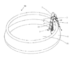
FIG. 5 is a view illustrating the application of the present ladder with barrier in an inflatable swimming pool; and
FIG. 6 is a view illustrating the application of the present ladder with barrier in a framed swimming pool.
Corresponding reference characters indicate corresponding parts throughout the several views. Although the drawings represent embodiments of the present invention, the drawings are not necessarily to scale and certain features may be exaggerated in order to better illustrate and explain the present invention.
DETAILED DESCRIPTION OF THE PREFERRED EMBODIMENTS
The embodiments disclosed below are not intended to be exhaustive or limit the invention to the precise forms disclosed in the following detailed description. Rather, the embodiments are chosen and described so that others skilled in the art may utilize their teachings.
As shown in FIG. 2, with reference also to FIG. 5, the present disclosure provides a swimming pool ladder 1 with a barrier 3. Ladder 1 includes two parallel rails 11 and four steps 12. When positioned in a pool 10, an inner or first section of ladder 1 is positioned within pool 10 and an outer or second section is positioned outside of pool 10. Ladder 1 further includes a top platform 2 (ladders without a platform are shown in FIGS. 2, 3B, 4C, 5, and 6′) for supporting a person connected between the upper portions of rails 11 and positioned above the inflatable swimming pool 10 as shown in FIG. 5. As shown in FIG. 6, the manner in which barrier 3 is mounted to ladder 1 in a frame swimming pool 10A is the same as that in inflatable swimming pool 10.
Steps 12 are mounted at intervals between the two rails 11 from top to bottom. The step 12 closest to top platform 2 is an uppermost or first step 121. The other steps 12 are respectively a second step 122, a third step 123, and a bottommost or fourth step 124. Barrier 3 is perpendicular to an inner side face 13 of ladder 1 positioned in pool 10. Barrier 3 has a triangle shape, one edge 14 of which is adjacent inner side face 13 of ladder 1 and fixed on second step 122 and fourth step 124 through connecting pieces 4, and another edge 15 of which is adjacent the inner sidewall of swimming pool 10.
As shown in FIG. 5, a top end 16 of barrier 3 is spaced from top platform 2 by a certain distance L, which distance L is preferably larger than the interval of two steps 12. The bottom end of the barrier 3 is parallel to floor 101 of swimming pool 10, with a gap formed therebetween. The gap is sized as to not to allow a child to penetrate therethrough.
As shown in FIG. 3A, a connector piece 4 is preferably a fixed-type connector 4. Fixed-type connectors 4 include clamps 41 and locking screws 43. One side of each clamp 41 is provided with a slot body 410 having a rectangular through slot 411 that accommodates the wall thickness of steps 12 of ladder 1. An outer sidewall 412 of slot body 410 is higher than an inner sidewall 413. A nut seat 414 having a threaded bore is provided on the upper end face of inner sidewall 413. Locking screw 43 is threadedly connected to nut seat 414. The threadedly connected end portion of locking screw 43 abuts against sidewall 13 of step 12. A snap slot 415 that is snap-engaged with upright tube 31 of barrier 3 is provided at the other side of each clamp 41.
Upon mounting, slot body 410 of clamp 41 is inserted onto sidewall 13 of step 12 (as shown in FIG. 3B). By rotating locking screws 43, a threadedly connected end portions of locking screws 43 abut against sidewall 13 of steps 12, and connector 4 is fixed on steps 12. Then, snap slot 415 of clamps 41 are snap-engaged with upright tube 31 of barrier 3, and mounting of barrier 3 is complete.
As shown in FIG. 4A and FIG. 4B, connector 4A is a swing-type connector 4A. Connector 4A comprises a left clamp 41A, a right clamp 42A, a locking screw 43A, a torsion spring 44A, and a pin 45A.
Left clamp 41A is provided with a slot body 410A having a rectangular through slot 411A that matches the wall thickness of steps 12A of ladder 1 (as shown in FIG. 4C). An outer sidewall 412A of slot body 410A is higher than an inner sidewall 413A. A nut seat 414A having a threaded bore 424A is provided on the upper end face of inner sidewall 413A as shown in FIG. 4D. Locking screw 43A is threadedly connected to nut seat 414A. Threadedly connected end portion 17A of locking screw 43A abuts against outer sidewall 412A.
A snap slot 421A of right clamp 42A is snap-engaged with upright tube 31A of barrier 3A (as shown in FIG. 4C). Left clamp 41A and right clamp 42A are pivotably connected together through a pin 45A, and said right clamp 42A may swing in relation to said left clamp 41A. Apertures 416A, 423A for receiving legs 47 of spring 44A are provided adjacent pin hole 415A of left clamp 41A and pin hole 422A of right clamp 42A. Torsion spring 44A covers pin 45A and is inserted within pin hole 415A of left clamp 41A. Legs 47 at one end of torsion spring 44A are positioned in straight aperture 416A adjacent to pin hole 415A of left gripper 41A, and leg 47 at other end of torsion spring 44A is positioned in slot 423A adjacent to pin hole 422A of right clamp 42A. Thus, a torsional restoring force for aligning left clamp 41A and right clamp 42A is generated.
The above mentioned barrier may be a framework with a mesh-like material tightened thereon (see FIG. 2), or a panel structure made of relatively soft materials (see FIG. 3B), which not only may serve the function of a barrier, but also may be easily pushed through water.
While this invention has been described as having an exemplary design, the present invention may be further modified within the spirit and scope of this disclosure. This application is therefore intended to cover any variations, uses, or adaptations of the invention using its general principles. Further, this application is intended to cover such departures from the present disclosure as come within known or customary practice in the art to which this invention pertains.

Claims (10)

The invention claimed is:
1. A swimming pool ladder with a barrier including
first and second ladder sections being positionable inside and outside a swimming pool, the first ladder section including a plurality of steps including an uppermost step,
a top support platform connecting upper portions of the first and second ladder sections, and
a triangular barrier having a first edge position adjacent the first ladder section and fixed to at least two steps with at least two connectors and a second edge positionable adjacent an inner sidewall of the swimming pool, a top end of the barrier is spaced apart from the top platform by a distance, wherein the triangular barrier includes a framework with at least one of the mesh material tightened thereon or a soft panel structure and at least one of the connector pieces includes a clamp having a slot body and a locking screw, the slot body includes a rectangular through slot that accommodates a thickness of a step.
2. The swimming pool ladder with barrier of claim 1, wherein the slot body includes an outer wall and an inner wall cooperating to define the rectangular through slot, the outer wall is higher than the inner wall.
3. The swimming pool ladder with barrier of claim 2, wherein an upper face of the inner side wall includes a nut seat having a threaded bore, the locking screw is threadedly connected to the nut seat, and an end portion of the locking screw abuts against at least one of the steps.
4. The swimming pool ladder with barrier of claim 1, wherein the clamp includes a snap slot that is snap-engaged with a upright tube of the barrier.
5. A swimming pool ladder with a barrier including
first and second ladder sections being positionable inside and outside a swimming pool, the first ladder section including a plurality of steps including an uppermost step,
a top support platform connecting upper portions of the first and second ladder sections, and
a triangular barrier having a first edge position adjacent the first ladder section and fixed to at least two steps with at least two connectors and a second edge positionable adjacent an inner sidewall of the swimming pool, a top end of the barrier is spaced apart from the top platform by a distance, wherein the at least one of the connectors includes a first clamp, a second clamp, a locking screw, a torsion spring, and a pin coupling the first clamp to the second clamp.
6. The swimming pool ladder with a barrier of claim 5, wherein the first clamp includes a rectangular through slot that accommodates the wall thickness of the step.
7. The swimming pool ladder with a barrier of claim 6, wherein the first clamp includes an outer wall and an inner wall that cooperate to define the rectangular through slot, the outer wall is higher than the inner wall.
8. The swimming pool ladder with a barrier of claim 7, wherein an upper end face of the inner wall includes a nut seat having a threaded bore, the locking screw is threadedly connected to the nut seat, and an end portion of the locking screw abuts against at least one of the steps.
9. The swimming pool ladder with a barrier of claim 5, wherein the second clamp includes a snap slot engaged with an upright tube of the barrier.
10. The swimming pool ladder with a barrier of claim 5, wherein the torsion spring includes legs and the first and second clamps include straight slots for receiving the legs of the torsion spring; the pin is covered by the torsion spring.
US12/853,668 2009-08-11 2010-08-10 Swimming pool ladder with a barrier Expired - Fee Related US8556033B2 (en)

Priority Applications (1)

Application Number Priority Date Filing Date Title
US12/870,410 US20110072574A1 (en) 2009-08-11 2010-08-27 Swimming Pool Ladder Cover

Applications Claiming Priority (9)

Application Number Priority Date Filing Date Title
CN2009201825788U CN201474344U (en) 2009-08-11 2009-08-11 Safeguarding device for plastic swimming pool
CN200920182579.2 2009-08-11
CN2009201825735U CN201474346U (en) 2009-08-11 2009-08-11 Swimming pool ladder with safe guarding device
CN200920182578.8 2009-08-11
CN200920182573U 2009-08-11
CN200920182573.5 2009-08-11
CN2009201825720U CN201539116U (en) 2009-08-11 2009-08-11 Baffle structure of pedals of ladder of swimming pool
CN200920182572.0 2009-08-11
CN2009201825792U CN201486178U (en) 2009-08-11 2009-08-11 Fastening device for stairs and swimming pool

Related Child Applications (1)

Application Number Title Priority Date Filing Date
US12/870,410 Continuation-In-Part US20110072574A1 (en) 2009-08-11 2010-08-27 Swimming Pool Ladder Cover

Publications (2)

Publication Number Publication Date
US20110073410A1 US20110073410A1 (en) 2011-03-31
US8556033B2 true US8556033B2 (en) 2013-10-15

Family

ID=43779066

Family Applications (1)

Application Number Title Priority Date Filing Date
US12/853,668 Expired - Fee Related US8556033B2 (en) 2009-08-11 2010-08-10 Swimming pool ladder with a barrier

Country Status (1)

Country Link
US (1) US8556033B2 (en)

Cited By (1)

* Cited by examiner, † Cited by third party
Publication number Priority date Publication date Assignee Title
US20130233647A1 (en) * 2009-01-07 2013-09-12 Polygroup Macau Limited (Bvi) Pool ladder safety system

Families Citing this family (2)

* Cited by examiner, † Cited by third party
Publication number Priority date Publication date Assignee Title
US9500028B2 (en) * 2013-08-12 2016-11-22 Compagnie Generale Des Etablissements Michelin Custom mold press ladder
US10214962B2 (en) * 2015-11-27 2019-02-26 Intex Marketing Ltd. Swimming pool ladder with safety gate

Citations (9)

* Cited by examiner, † Cited by third party
Publication number Priority date Publication date Assignee Title
US4418792A (en) * 1982-03-03 1983-12-06 Cerone Daniel J Pool ladder
US5065840A (en) * 1990-11-05 1991-11-19 Lloyd Cadigan Swimming pool safety ladder
US5992563A (en) * 1998-11-13 1999-11-30 Skyller Associates L.L.C. Multipiece interfitting steps for a swimming pool
USD449895S1 (en) * 2000-12-19 2001-10-30 Jean L. Wilson Combined swimming pool steps and ladder
US20030132059A1 (en) * 2002-01-13 2003-07-17 Saputo Richard A. Swimming pool ladder
US20090308003A1 (en) * 2008-06-17 2009-12-17 Bernard Juneau Swimming pool stairs
US20100044153A1 (en) * 2008-08-19 2010-02-25 Confer Plastics, Inc. A-Frame Ladder with a Flexible Gate/Barrier
US20100170749A1 (en) * 2009-01-07 2010-07-08 Leung Chi Yin Alan Pool ladder safety system
US20120079651A1 (en) * 2010-10-05 2012-04-05 Canadian Plastics Inc. Stair assembly for swimming pool

Patent Citations (10)

* Cited by examiner, † Cited by third party
Publication number Priority date Publication date Assignee Title
US4418792A (en) * 1982-03-03 1983-12-06 Cerone Daniel J Pool ladder
US5065840A (en) * 1990-11-05 1991-11-19 Lloyd Cadigan Swimming pool safety ladder
US5992563A (en) * 1998-11-13 1999-11-30 Skyller Associates L.L.C. Multipiece interfitting steps for a swimming pool
USD449895S1 (en) * 2000-12-19 2001-10-30 Jean L. Wilson Combined swimming pool steps and ladder
US20030132059A1 (en) * 2002-01-13 2003-07-17 Saputo Richard A. Swimming pool ladder
US20090308003A1 (en) * 2008-06-17 2009-12-17 Bernard Juneau Swimming pool stairs
US20100044153A1 (en) * 2008-08-19 2010-02-25 Confer Plastics, Inc. A-Frame Ladder with a Flexible Gate/Barrier
US20100170749A1 (en) * 2009-01-07 2010-07-08 Leung Chi Yin Alan Pool ladder safety system
GB2466873A (en) * 2009-01-07 2010-07-14 Cindex Holdings Ltd Swimming pool ladder guard
US20120079651A1 (en) * 2010-10-05 2012-04-05 Canadian Plastics Inc. Stair assembly for swimming pool

Non-Patent Citations (1)

* Cited by examiner, † Cited by third party
Title
Confer Plastics Inc., "The Leader in Ladders Brochure", Dec. 2008, p. 2. *

Cited By (3)

* Cited by examiner, † Cited by third party
Publication number Priority date Publication date Assignee Title
US20130233647A1 (en) * 2009-01-07 2013-09-12 Polygroup Macau Limited (Bvi) Pool ladder safety system
US8955644B2 (en) * 2009-01-07 2015-02-17 Polygroup Macau Limited (Bvi) Pool ladder safety system
US9394744B2 (en) 2009-01-07 2016-07-19 Polygroup Macau Limited (Bvi) Pool ladder safety system

Also Published As

Publication number Publication date
US20110073410A1 (en) 2011-03-31

Similar Documents

Publication Publication Date Title
KR100816296B1 (en) Connecting structure of cable tray
US7895953B2 (en) Structural support for a food guard apparatus
KR101307486B1 (en) Cable tray
US10415255B2 (en) Handrail and railing assembly
US8556033B2 (en) Swimming pool ladder with a barrier
EP3243555B1 (en) Spring enclosed trampoline
BR112019010845A2 (en) universal end fastener for fastening solar panels to rail support guide
US9444395B2 (en) Support assembly for mounting a solar panel unit
US9689519B2 (en) Trampoline support structure
US20150082735A1 (en) Post support bracket system
US20170319886A1 (en) Spring Enclosed Trampoline
KR100979499B1 (en) Bed with bracket for fixing side plate
KR20120123759A (en) A connecting apparatus of deck
KR20160143099A (en) Wood deck assembly and method thereof
KR101144052B1 (en) The roof-fixing frame for an arkade constructure
KR200437661Y1 (en) structure for adjusting height for a frame chair
JP5587587B2 (en) End bracket
KR20190000325U (en) Fixing apparatus
US20190345716A1 (en) Structural support system
JP6857037B2 (en) Structure
CN211949060U (en) Fast-assembling frame in shower room
JP7117716B2 (en) Horizontal rail fixing member and handrail support device provided with the same
JP2002348968A (en) Brace installing structure
KR200491999Y1 (en) Structure
JP2013124451A (en) Column for handrail

Legal Events

Date Code Title Description
AS Assignment

Owner name: INTEX RECREATION CORP., CALIFORNIA

Free format text: ASSIGNMENT OF ASSIGNORS INTEREST;ASSIGNOR:HSIANG, HUA;REEL/FRAME:025501/0550

Effective date: 20101108

STCF Information on status: patent grant

Free format text: PATENTED CASE

AS Assignment

Owner name: INTEX MARKETING LTD., VIRGIN ISLANDS, BRITISH

Free format text: ASSIGNMENT OF ASSIGNORS INTEREST;ASSIGNOR:INTEX RECREATION CORP.;REEL/FRAME:038336/0844

Effective date: 20160418

FPAY Fee payment

Year of fee payment: 4

FEPP Fee payment procedure

Free format text: MAINTENANCE FEE REMINDER MAILED (ORIGINAL EVENT CODE: REM.); ENTITY STATUS OF PATENT OWNER: LARGE ENTITY

LAPS Lapse for failure to pay maintenance fees

Free format text: PATENT EXPIRED FOR FAILURE TO PAY MAINTENANCE FEES (ORIGINAL EVENT CODE: EXP.); ENTITY STATUS OF PATENT OWNER: LARGE ENTITY

STCH Information on status: patent discontinuation

Free format text: PATENT EXPIRED DUE TO NONPAYMENT OF MAINTENANCE FEES UNDER 37 CFR 1.362

FP Lapsed due to failure to pay maintenance fee

Effective date: 20211015