US8542312B2 - Device having image reconstructing function, method, and storage medium - Google Patents
Device having image reconstructing function, method, and storage medium Download PDFInfo
- Publication number
- US8542312B2 US8542312B2 US13/434,024 US201213434024A US8542312B2 US 8542312 B2 US8542312 B2 US 8542312B2 US 201213434024 A US201213434024 A US 201213434024A US 8542312 B2 US8542312 B2 US 8542312B2
- Authority
- US
- United States
- Prior art keywords
- image
- sub
- pixel
- lens
- line
- Prior art date
- Legal status (The legal status is an assumption and is not a legal conclusion. Google has not performed a legal analysis and makes no representation as to the accuracy of the status listed.)
- Expired - Fee Related, expires
Links
- 238000000034 method Methods 0.000 title claims description 49
- 230000003287 optical effect Effects 0.000 claims abstract description 37
- 230000006870 function Effects 0.000 claims description 9
- 239000000284 extract Substances 0.000 claims description 3
- 238000012545 processing Methods 0.000 description 35
- 238000011156 evaluation Methods 0.000 description 14
- 238000003384 imaging method Methods 0.000 description 14
- 238000000605 extraction Methods 0.000 description 12
- 238000003491 array Methods 0.000 description 6
- 239000013256 coordination polymer Substances 0.000 description 5
- 238000010586 diagram Methods 0.000 description 3
- 230000008859 change Effects 0.000 description 2
- 239000004973 liquid crystal related substance Substances 0.000 description 2
- 230000007246 mechanism Effects 0.000 description 2
- 230000000737 periodic effect Effects 0.000 description 2
- 230000008569 process Effects 0.000 description 2
- 230000008901 benefit Effects 0.000 description 1
- 230000015572 biosynthetic process Effects 0.000 description 1
- 238000004891 communication Methods 0.000 description 1
- 230000000295 complement effect Effects 0.000 description 1
- 238000011161 development Methods 0.000 description 1
- 238000005401 electroluminescence Methods 0.000 description 1
- 238000002474 experimental method Methods 0.000 description 1
- 230000007274 generation of a signal involved in cell-cell signaling Effects 0.000 description 1
- 230000010354 integration Effects 0.000 description 1
- 229910044991 metal oxide Inorganic materials 0.000 description 1
- 150000004706 metal oxides Chemical class 0.000 description 1
- 238000012986 modification Methods 0.000 description 1
- 230000004048 modification Effects 0.000 description 1
- 238000010606 normalization Methods 0.000 description 1
- 239000004065 semiconductor Substances 0.000 description 1
Images


Classifications
-
- G—PHYSICS
- G06—COMPUTING; CALCULATING OR COUNTING
- G06T—IMAGE DATA PROCESSING OR GENERATION, IN GENERAL
- G06T5/00—Image enhancement or restoration
- G06T5/50—Image enhancement or restoration using two or more images, e.g. averaging or subtraction
-
- H—ELECTRICITY
- H04—ELECTRIC COMMUNICATION TECHNIQUE
- H04N—PICTORIAL COMMUNICATION, e.g. TELEVISION
- H04N23/00—Cameras or camera modules comprising electronic image sensors; Control thereof
- H04N23/80—Camera processing pipelines; Components thereof
- H04N23/84—Camera processing pipelines; Components thereof for processing colour signals
- H04N23/843—Demosaicing, e.g. interpolating colour pixel values
-
- G—PHYSICS
- G02—OPTICS
- G02B—OPTICAL ELEMENTS, SYSTEMS OR APPARATUS
- G02B27/00—Optical systems or apparatus not provided for by any of the groups G02B1/00 - G02B26/00, G02B30/00
- G02B27/0075—Optical systems or apparatus not provided for by any of the groups G02B1/00 - G02B26/00, G02B30/00 with means for altering, e.g. increasing, the depth of field or depth of focus
-
- G—PHYSICS
- G06—COMPUTING; CALCULATING OR COUNTING
- G06T—IMAGE DATA PROCESSING OR GENERATION, IN GENERAL
- G06T3/00—Geometric image transformations in the plane of the image
- G06T3/40—Scaling of whole images or parts thereof, e.g. expanding or contracting
- G06T3/4007—Scaling of whole images or parts thereof, e.g. expanding or contracting based on interpolation, e.g. bilinear interpolation
-
- H—ELECTRICITY
- H04—ELECTRIC COMMUNICATION TECHNIQUE
- H04N—PICTORIAL COMMUNICATION, e.g. TELEVISION
- H04N23/00—Cameras or camera modules comprising electronic image sensors; Control thereof
- H04N23/60—Control of cameras or camera modules
- H04N23/67—Focus control based on electronic image sensor signals
-
- G—PHYSICS
- G06—COMPUTING; CALCULATING OR COUNTING
- G06T—IMAGE DATA PROCESSING OR GENERATION, IN GENERAL
- G06T2200/00—Indexing scheme for image data processing or generation, in general
- G06T2200/21—Indexing scheme for image data processing or generation, in general involving computational photography
-
- G—PHYSICS
- G06—COMPUTING; CALCULATING OR COUNTING
- G06T—IMAGE DATA PROCESSING OR GENERATION, IN GENERAL
- G06T2207/00—Indexing scheme for image analysis or image enhancement
- G06T2207/20—Special algorithmic details
- G06T2207/20212—Image combination
- G06T2207/20221—Image fusion; Image merging
Definitions
- This application relates to an image-reconstructing technique.
- Cameras capturing an image (hereinafter referred to as a lens array image) formed by an array of multiple microlenses (a microlens array, hereafter) LA 11 from an image of an object formed by a main lens LM as shown in FIG. 22 are known.
- images formed by a microlens array LA 11 have parallax corresponding to the lens pitch 2dr of the microlenses and/or the like.
- This parallax causes some pixels necessary for reconstructing an image OB to be missing from a lens array image (namely, missing pixels occur). Then, a problem is that the reconstructed image OB has noise appearing as periodic change in brightness of the image as shown in a part Nz of FIG. 23 .
- an image information acquiring section that acquires information forming a lens array image, the lens array image is formed by a lens array comprising an array of sub-lenses including a first sub-lens and a second sub-lens for an optical image of an object formed by a main lens;
- an interpolating section that interpolates a third sub-image formed by a third sub-lens based on a first sub-image and a second sub-image constituting the lens array image, wherein the third sub-lens is positioned between the first sub-lens forming the first sub-image and the second sub-lens forming the second sub-image;
- a distance information acquiring section that acquires distance information indicating a distance to a point on which the main lens focuses
- a reconstructing section that reconstructs an image of the object formed by the main lens focused on the point at the distance indicated by the acquired distance information from the interpolated third sub-image, the first sub-image and the second sub-image;
- an image information outputting section that outputs information forming the reconstructed image.
- the image reconstructing method includes the steps of:
- the lens array image is formed by a lens array comprising an array of sub-lenses including a first sub-lens and a second sub-lens for an optical image of an object formed by a main lens;
- the non-transitory computer-readable storage medium stores a program executable by a computer, causing the computer to realize functions of:
- the lens array image is formed by a lens array comprising an array of sub-lenses including a first sub-lens and a second sub-lens for an optical image of an object formed by a main lens;
- FIGS. 1A and 1B are diagrams presenting a digital camera in which the image reconstructing device is installed
- FIG. 2 is an illustration presenting a lens array of a digital camera
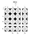
- FIG. 3 is an illustration presenting a light field image
- FIGS. 4A and 4B are flowcharts presenting an image reconstruction procedure
- FIG. 5A is a diagram presenting functions of an image reconstructing device
- FIG. 5B is a diagram presenting functions of an interpolation part
- FIG. 6 is an illustration presenting an exemplary epipolar plane
- FIG. 7 is a flowchart presenting an epipolar image ES creation procedure
- FIG. 8A is an illustration presenting an epipolar image ES
- FIG. 8B is an illustration presenting an epipolar image ET
- FIG. 9 is an illustration presenting pixel lines on epipolar planes of the light field image
- FIG. 10 is an illustration presenting an epipolar image ES in detail
- FIG. 11 is an illustration presenting an interpolated lens array
- FIG. 12 is an illustration presenting interpolated light field images
- FIG. 13 is an illustration presenting an interpolated epipolar image CES mk ;
- FIG. 14 is a flowchart presenting an angle S presumption procedure
- FIG. 15 is an illustration presenting a presumed angle S table
- FIGS. 16A and 16B are flowcharts presenting a pixel S interpolation procedure
- FIG. 17 is an illustration for explaining a line presumption method
- FIG. 18 is an illustration presenting an interpolated pixel table
- FIG. 19 is an illustration presenting an interpolated epipolar image CET nl ;
- FIGS. 20A and 20B are flowcharts presenting a reconstructed image creation procedure
- FIG. 21 is an illustration for explaining another line presumption method
- FIG. 22 is an illustration presenting an optical device of a digital camera.
- FIG. 23 is a photographic image presenting noise appearing in a reconstructed image.
- a device having an image reconstructing function (an image reconstructing device, hereafter) 210 according to an embodiment of the present invention will be described hereafter with reference to the attached drawings.
- the image reconstructing device 210 according to an embodiment of the present invention is installed in a digital camera 1 as shown in FIG. 1A .
- the image reconstructing device 210 reconstructs an image in focus at any distance from an image captured by the digital camera 1 .
- the digital camera 1 comprises an imaging part 100 , a data processing part 200 including the image reconstructing device 210 according to the present invention, and an interface part (an OF part in the FIG. 300 .
- the imaging part 100 conducts imaging operation of the digital camera 1 and comprises an optical device 110 and an image sensor 120 .
- the optical device 110 includes a main lens LM and a lens array LA 11 forming an image of an optical image formed by the main lens LM as shown in FIG. 22 and a not-shown diaphragm mechanism and shutter mechanism, and conducts optical operation regarding image formation.
- the lens array LA 11 consists of sub-lenses (microlenses, hereafter) L 11 to L MN as shown in FIG. 2 arranged in the number of M at a vertical pitch of 2dr (namely, in the subscan direction) and in the number of N at a horizontal pitch of 2dr (namely, in the main scan direction).
- the image sensor 120 comprises an imaging element such as a CCD (charge coupled device) and CMOS (complementary metal oxide semiconductor).
- the image sensor 120 generates electric signals according to incident light collected by the lens array LA 11 of the optical device 110 and outputs the generated electric signals to the data processing part 200 .
- the data processing part 200 conducts signal-processing on analogue electric signals generated by the imaging part 100 to create digital data (namely, image data) forming a lens array image (also termed a light field image, hereafter) LF 11 as shown in FIG. 3 formed by the lens array LA 11 , and conducts various image-processing on the created image.
- digital data namely, image data
- a lens array image also termed a light field image, hereafter
- the data processing part 200 comprises an image reconstructing device 210 , an image processing part 220 , a storage 230 , and an image output part 240 .
- the image reconstructing device 210 comprises, for example, an LSI (large scale integration) comprising a CPU (central processing unit) 210 a , a RAM (random access memory) 210 b , a ROM (read only memory) 210 c , and an I/O port 210 d as shown in FIG. 1B .
- LSI large scale integration
- the CPU 210 a executes software processing according to programs stored in the ROM 210 c to control the parts of the digital camera 1 including the image reconstructing device 210 (namely, the total control).
- the RAM 210 b temporarily stores information (data) to process while the CPU 210 a executes programs.
- the I/O port 210 d inputs/outputs data between the parts connected to the image reconstructing device 210 and the CPU 210 a.
- the image processing part 220 comprises, for example, a buffer memory, an AD (analog/digital) converter, and a processor for image processing.
- the AD converter of the image processing part 220 converts analog electric signals output from the image sensor 120 to digital signals.
- the processor of the image processing part 220 conducts so-called development process to create image data, for example, JPEG (joint photographic experts group) and bitmap data, and stores the created image data in the storage 230 .
- the storage 230 comprises a storage device, for example, a DRAM (dynamic random access memory) and flash memory, storing image data created by the image processing part 220 and image data created by the image reconstructing device 210 .
- a storage device for example, a DRAM (dynamic random access memory) and flash memory, storing image data created by the image processing part 220 and image data created by the image reconstructing device 210 .
- the image output part 240 comprises, for example, a liquid crystal display controller or RGB signal generation circuit, converting image data output from the image reconstructing device 210 and/or image data stored in the storage 230 to RGB signals and/or the like and outputting the RGB signals to a display part 320 described later.
- the interface part 300 serves as interface between the digital camera 1 and its user or an external device and comprises an external interface part 310 , a display part 320 , and an operation part 330 .
- the external interface part 310 comprises, for example, a USB (universal serial bus) connector and/or video output terminal, serving in output of image data to an external computer device, output of display of an image to an external monitor device, uploading of programs from a recording medium, reading of image data, writing of image data on a recording medium, and the like.
- a USB universal serial bus
- the display part 320 comprises, for example, a liquid crystal display device and/or organic EL (electroluminescence) display.
- the display part 320 displays various screens necessary for operating the digital camera 1 and various images based on image signals (RGB signals) from the image output part 240 .
- the operation part 330 comprises various buttons provided on the exterior of the digital camera 1 and/or the like, generating operation signals in accordance with operation by the user of the digital camera 1 and entering the generated operation signals into the image reconstructing device 210 .
- the CPU 210 a of the image reconstructing device 210 functions as an image information acquisition part 211 , an interpolation part 212 , a distance information acquisition part 214 , a reconstruction part 215 , and an image information output part 216 as shown in FIG. 5A .
- the interpolation part 212 in FIG. 5A has an extraction part 212 a , a creation part 212 b , a line presumption part 212 c , a pixel presumption part 212 d , and a pixel value determination part 212 e as shown in FIG. 5B .
- the distance information acquisition part 214 executes a set value acquisition procedure to acquire various set values (Step S 01 ). More specifically, the distance information acquisition part 214 acquires distance information indicating the distance between the digital camera 1 and a focusing point on which the main lens
- the distance information acquisition part 214 acquires various pieces of information presenting predetermined internal parameters (namely, constants specific for the digital camera 1 ) from the storage 230 .
- the image information acquisition part 211 reads image data forming a captured light field image LF 11 from the storage 230 (Step S 02 ).
- the light field image LF 11 in FIG. 3 consists of sub-images S 11 to S MN formed by the microlenses L 11 to L MN constituting the lens array LA 11 in FIG. 2 , respectively.
- the sub-images S 11 to S MN each have parallax.
- the optical center O mn+1 determined by a lens L mn+1 is spaced from the optical center O mn determined by a lens L mn by the lens pitch 2dr in the main scan direction (namely, in the +x-axis direction of the world coordinate system).
- the epipolar plane O mn O mn+1 P determined by the optical centers O mn and O mn+1 and a point P on the object OJ is parallel to the main scan direction (namely, the u-axis of a uv image coordinate system parallel to the x-axis direction).
- a point P mn presenting the point P on the object OJ in a sub-image S mn and a point P mn+1 presenting the point P in a sub-image S mn+1 are present on the epipolar plane O mn O mn+1 P parallel to the u-axis.
- the difference between the points P mn and P mn+1 on the uv image coordinate system manifests as parallax.
- a line of pixels (a pixel line, hereafter) on the epipolar plane O mn O mn+1 P in a sub-image S mn and a pixel line on the epipolar plane O mn O mn+1 P in a sub-image S mn+1 cause parallax only in the main scan direction (namely, in the u-axis direction).
- the interpolation part 212 executes an epipolar image ES creation procedure as shown in FIG. 7 (Step S 03 ).
- the epipolar image ES creation procedure is a procedure to create epipolar images ES 11 to ES MK as shown in FIG. 8A from the light field image LF 11 formed by the image data read in the Step S 02 .
- the +s direction (namely, the main scan direction) and the +t direction (namely, the subscan direction) of the st image coordinate system of the light field image LF 11 are parallel to the u-axis direction and the v-axis direction of the uv image coordinate system of the sub-images S 11 to S mN of the light field image LF 11 , respectively.
- the sub-images S m1 to S mN each have L pixels in the s direction and K pixels in the t direction (however, the numbers of pixels K and L are generally equal).
- the extraction part 212 a of the interpolation part 212 initializes a value of a variable m to “1” (Step S 31 ). Then, the extraction part 212 a determines whether the value of the variable m is equal to or lower than a value M (equal to or lower than the number of microlenses arranged in the subscan direction) (Step S 32 ).
- Step S 32 If the value of the variable m is equal to or lower than the value M (Step S 32 ; Yes), the extraction part 212 a initializes a value of a variable k to “1” (Step S 33 ). Then, the extraction part 212 a determines whether the value of the variable k is equal to or lower than a value K (equal to or lower than the number of pixels in the subscan direction of a sub-image) (Step S 34 ).
- Step S 34 If the value of the variable k is equal to or lower than the value K (Step S 34 ; Yes), the extraction part 212 a initializes a value of a variable n to “1” (Step S 35 ). Then, the extraction part 212 a determines whether the value of the variable n is equal to or lower than a value N (equal to or lower than the number of microlenses arranged in the main scan direction) (Step S 36 ).
- Step S 36 If the value of the variable n is equal to or lower than the value N (Step S 36 ; Yes), the extraction part 212 a extracts the pixel line on the k-th epipolar S plane from the sub-image S mn , and the creation part 212 b creates an epipolar image ES mk having the extracted pixel line at the n-th tier (Step S 37 ).
- the extraction part 212 a increments the value of the variably n by “1” (Step S 38 ) and repeats the above processing from the Step S 36 .
- Step S 36 If the value of the variable n is greater than the value N in the Step S 36 (Step S 36 ; No), the extraction part 212 a increments the value of the variable k by “1” (Step S 39 ) and repeats the above processing from the Step S 34 .
- Step S 34 If the value of the variable k is greater than the value K in the Step S 34 (Step S 34 ; No), the extraction part 212 a increments the value of the variable m by “1” (Step S 40 ) and repeats the above processing from the Step S 32 .
- Step S 32 If the value of the variable m is greater than the value M in the Step S 32 (Step S 32 ; No), the extraction part 212 a ends the epipolar image ES creation procedure.
- the epipolar image ES mk is created by arranging the pixel lines on the k-th epipolar S plane in the sub-images S m1 to S mN in N tiers as shown in FIG. 10 .
- the microlenses L m1 to L mN are arranged at the lens pitch 2dr in the main scan direction.
- the centers of the microlenses L m1 to L mN (namely, the optical centers) are situated at a nearly equal distance from a point P on the object OJ.
- the other internal parameters do not change.
- the difference in u-coordinate value between a pixel presenting the point P mn ⁇ 1 on the pixel line at the n ⁇ 1-th tier and a pixel presenting the point P mn on the pixel line at the n-th tier in the epipolar image ES mk is nearly equal to the difference in u-coordinate value between the point P mn and a pixel presenting the point P mn+1 on the pixel line at the n+1-th tier. Then, the points P mn ⁇ 1 , P mn , and P mn+1 are present on one and the same line in the epipolar image ES mk .
- a lens array LA 12 having the same lens configuration as the lens array LA 11 is placed at a position shifted from the position of the lens array LA 11 by a pitch 2dr/H that is 1/H of the lens pitch 2dr of the lens array LA 11 in the +s direction as shown in FIG. 11 .
- a lens array LA 13 having the same lens configuration as the lens array LA 11 is placed at a position shifted from the position of the lens array LA 11 by a pitch 2 ⁇ (2dr/H) in the +s direction.
- up to the lens array LA 1H is placed.
- the sub-images S 11 and S mN have L pixels in the s direction.
- the light field images LF 12 to LF 1H formed by the assumed lens arrays LA 12 to LA 1H are situated at positions shifted from the light field image LF 11 by L/H, 2 ⁇ (L/H), . . . , and (H ⁇ 1) ⁇ (L/H), respectively, in the +s direction as shown in FIG. 12 .
- the interpolation part 212 executes an interpolated epipolar image CES creation procedure (Step S 04 ).
- the inserted (H ⁇ 1) tiers store (H ⁇ 1) pixel lines that are, from the lowest-numbered tier, the k-th pixel line of the sub-image S mn of the light field image LF 12 , the k-th pixel line of the sub-image S mn of the light field image LF 13 , . . . , and the k-th pixel line of the sub-image S mn of the light field image LF 1H , of which the pixel values have not been determined.
- the image in which the (H ⁇ 1) pixel lines are inserted is termed an interpolated epipolar image CES mk .
- the lens pitch, distance to a point P, and internal parameters are constant.
- points P mn and P mn+1 projected from a point P on the object OJ are present in the sub-images S mn and S mn+1 of the light field image LF 11 , points P 12mn , P 13mn , . . . , and P 1Hmn (the corresponding points to a point P mn , hereafter) projected from the point P on the object OJ are present in the sub-images S mn of the interpolated light field images LF 12 , . . . , LF 1H .
- the parallax is nearly constant. Therefore, the difference in u-coordinate value between the pixels presenting the points P mn and P 12nm , the difference in u-coordinate value between the pixels presenting the points P 12mn and P 13mn , . . . , and the difference in u-coordinate value between the pixels presenting the points P 1Hmn and P mn+1 in the interpolated epipolar image CES mk are nearly equal. Therefore, these points P mn , P 12mn , . . . , P 1Hmn , and P mn+1 are present on one and the same line in the interpolated epipolar image CES mk .
- the above line is termed “the corresponding pixel line” hereafter.
- the corresponding pixel line is specified by the pixels through which the line passes and the angle ⁇ between the line and the u-coordinate axis (which can be the v-coordinate axis).
- the distance between a microlens L mn and a point P on the object OJ varies depending on the point P on the object OJ.
- the difference in u-coordinate value namely, parallax
- the angle ⁇ of the corresponding pixel line varies depending on the P on the object OJ presented by the pixels through which the line passes.
- the line presumption part 212 c executes an angle S presumption procedure as shown in FIG. 14 to presume the angle of the corresponding pixel line in the interpolated epipolar image CES mk (Step S 05 ).
- the line presumption part 212 c initializes a value of a variable m to “1” (Step S 41 ). Then, the line presumption part 212 c determines whether the value of the variable m is equal to or lower than a value M (Step S 42 ).
- Step S 42 If the value of the variable m is equal to or lower than the value M (Step S 42 ; Yes), the line presumption part 212 c initializes a value of a variable k to “1” (Step S 43 ). Then, the line presumption part 212 c determines whether the value of the variable k is equal to or lower than a value K (Step S 44 ).
- Step S 44 If the value of the variable k is equal to or lower than the value K (Step S 44 ; Yes), the line presumption part 212 c initializes a value of a variable n to “1” (Step S 45 ). Then, the line presumption part 212 c determines whether the value of the variable n is equal to or lower than a value N (Step S 46 ).
- Step S 46 If the value of the variable n is equal to or lower than the value N (Step S 46 ; Yes), the line presumption part 212 c initializes a value of a variable l to “1” (Step S 47 ). Then, the line presumption part 212 c determines whether the value of the variable l is equal to or lower than a value L (Step S 48 ).
- the line presumption part 212 c calculates an evaluation value Line ( ⁇ ) of the line EPL of an angle ⁇ passing through a pixel E 11nl that is the l-th pixel (namely, a pixel having the l-th lowest u-coordinate value) on the k-th pixel line of the sub-image S mn of the light field image LF 11 in the interpolated epipolar image CES shown in FIG. 13 using the formula (I) below (Step S 49 ).
- the evaluation value is an index for how different a pixel q on the line EPL of an angle ⁇ passing through the pixel E 11nl from the pixel E 11nl .
- EPI is a set of pixels on the line passing through the pixel E 11nl
- q is an element of the set
- Q is the number of elements in the set
- I q is the pixel value of an element q (namely, a pixel on the line)
- I 11nl is the pixel value of the pixel E 11nl .
- the sum of absolute values of the differences between the pixel value L 11nl of the pixel E 11nl and the pixel values I q of the pixels q on the line is divided by Q, the number of pixels on the line, because the number of pixels q on the line varies depending on the angle of the line (namely, for normalization).
- the line presumption part 212 c designates the angle ⁇ yielding the lowest evaluation value as the optimum angle ⁇ *. Then, the line presumption part 212 c presumes that the optimum angle ⁇ * is the angle of the corresponding pixel line passing through the pixel E 11nl .
- the angle ⁇ of the corresponding pixel line passing through the pixel E 11nl varies depending on the distance to the point P presented by the pixel E 11nl (namely, the object distance).
- the optimum angle ⁇ * serves as an index for the object distance (namely, depth information).
- the evaluation value Line ( ⁇ *) serves as an index value presenting how likely the angle ⁇ of the corresponding pixel line is to be the angle ⁇ *.
- the line presumption part 212 c determines whether the evaluation value Line ( ⁇ *) is equal to or greater than a predetermined threshold th (Step S 50 ). If the evaluation value Line ( ⁇ *) is equal to or greater than the predetermined threshold th (Step S 50 ; Yes), the line presumption part 212 c associates and stores information identifying the interpolated epipolar image CES mk (the interpolated epipolar image ID, hereafter), information identifying the pixel E 11nl through which the corresponding pixel line passes (the pixel ID, hereafter), and information presenting the presumed angle ⁇ * in a presumed angle S table of FIG. 15 stored in the storage 230 (Step S 51 ).
- the interpolated epipolar image ID is presented by the values of the variables m and k.
- the pixel ID is presented by the values of the variables n and l.
- the threshold th is stored in the storage 230 in advance.
- the threshold th can be an optimum value determined through experiments by a person of ordinary skill in the art.
- the threshold th may be set to a value specified by the user based on signals output from the operation part 330 operated by the user.
- the line presumption part 212 c does not store information presenting the presumed angle ⁇ * in the presumed angle S table of FIG. 15 , but associates and stores information indicating that the presumed angle ⁇ * is unknown and the interpolated epipolar image ID and pixel ID.
- the line presumption part 212 c presumes that the line of the angle ⁇ * passing through the pixel E 11nl may not be the line passing through multiple pixels presenting the same point P on the object OJ, and stores information indicating that the presumed angle ⁇ * is unknown in the presumed angle S table of FIG. 15 .
- Step S 52 the line presumption part 212 c increments the value of the variable l by “1” (Step S 52 ) and repeats the above processing from the Step S 48 .
- Step S 48 If the value of the variable l is greater than the value L in the Step S 48 (Step S 48 ; No), the line presumption part 212 c increments the value of the variable n by “1” (Step S 53 ) and repeats the above processing from the Step S 46 .
- Step S 46 If the value of the variable n is greater than the value N in the Step S 46 (Step S 46 ; No), the line presumption part 212 c increments the value of the variable k by “1” (Step S 54 ) and repeats the above processing from the Step S 44 .
- Step S 44 If the value of the variable k is greater than the value K in the Step S 44 (Step S 44 ; No), the line presumption part 212 c increments the value of the variable m by “1” (Step S 55 ) and repeats the above processing from the Step S 42 .
- Step S 42 If the value of the variable m is greater than the value M in the Step S 42 (Step S 42 ; No), the line presumption part 212 c ends the angle S presumption procedure.
- the pixel presumption part 212 d executes the same processing as of the Steps S 41 to S 48 of FIG. 14 (Steps S 61 to S 68 ).
- the pixel presumption part 212 d acquires from the presumed angle S table of FIG. 15 information presenting the presumed angle ⁇ * associated with the interpolated epipolar image ID of the interpolated epipolar image CES mk (namely, the values of the variables m and k) and the pixel ID of the pixel E 11nl (namely, the values of the variables n and l) (Step S 69 ).
- the pixel presumption part 212 d determines whether information presenting the presumed angle ⁇ * is acquired (namely, whether information presenting the presumed angle ⁇ * associated with the values of the variables m, k, n, and l is stored) (Step S 70 ). If information presenting the presumed angle ⁇ * is acquired (Step S 70 ; Yes), the pixel presumption part 212 d initializes a value of a variable h to “2” (Step S 71 ).
- the pixel presumption part 212 d determines whether the value of the variable h is equal to or lower than a value H (Step S 72 ). If the value of the variable h is equal to or lower than a value H (Step S 72 ; Yes), the pixel presumption part 212 d presumes a corresponding pixel based on the intersection between the pixel line of the sub-image S mn of the light field image LF 1h and the presumed line (Step S 73 ).
- the pixel presumption part 212 d assumes that the center of the l-th pixel constituting the k-th pixel line of the sub-image S mn of the interpolated light field image LF 1h in the interpolated epipolar image CES is C hl .
- the pixel presumption part 212 d identifies the intersection CP h between the line passing through the centers C h1 to C hL and parallel to the u-axis (the interpolated pixel line, hereafter) and the corresponding pixel line. Then, the pixel presumption part 212 d identifies two centers C ha and C hb on either side of the intersection CP h .
- the pixel presumption part 212 d presumes that the pixel E 1hna having the center C ha and the pixel E 1hnb having the center C hb are the pixels presenting the corresponding point P 1hmn to the point P mn presented by the pixel E 11nl .
- the pixel value determination part 212 e determines the pixel values of the corresponding pixels E 1hna and E 1hnb presumed in the Step S 73 based on the pixel value I 11nl of the pixel E 11nl (Step S 74 ).
- the pixel value determination part 212 e calculates the distance r ha between the identified center C ha and intersection CP h and the distance r hb between the identified center C hb and intersection CP h . Then, the pixel value determination part 212 e determines a value ⁇ I 1hna to be added to the pixel value I 1hna of the corresponding pixel E 1hna and a value ⁇ I 1hnb to be added to the pixel value I 1hnb of the corresponding pixel E 1hnb .
- ⁇ I 1hna r hb /( r ha +r hb ) ⁇ I 11nl
- ⁇ I 1hnb r ha /( r ha +r hb ) ⁇ I 11nl (3)
- r hb /(r ha +r hb ) and r ha /(r ha +r hb ) are weighting coefficients.
- the pixel value determination part 212 e makes reference, from the storage 230 , to an interpolated pixel table as shown in FIG. 18 in which the pixel values of pixels constituting an interpolated light field image (the interpolated light field image, hereafter) LF 1h are stored.
- the pixel value determination part 212 e acquires information presenting the pixel value I 1hna associated with the interpolated epipolar image ID presented by the values of the variables m and k and the pixel ID of the corresponding pixel E 1hna presented by the value of the variable n and a specified value a. Then, the pixel value determination part 212 e redetermines the sum of the pixel value I 1hna and additional value ⁇ I 1hna to be the pixel value I 1hna of the corresponding pixel E 1hna .
- the pixel value determination part 212 e acquires information presenting the pixel value I 1hnb associated with the interpolated epipolar image ID and the pixel ID of the corresponding pixel E 1hnb . Then, the pixel value determination part 212 e redetermines the sum of the pixel value I 1hnb and additional value ⁇ I 1hnb to be the pixel value I 1hnb of the corresponding pixel E 1hnb (Step S 74 ).
- the pixel value determination part 212 e updates information associated with the interpolated epipolar image ID and the pixel ID of the corresponding pixel E 1hna using information presenting the determined pixel value T 1hna .
- the pixel value determination part 212 e updates information associated with the interpolated epipolar image ID and the pixel ID of the corresponding pixel E 1hnb using information presenting the determined pixel value I 1hnb (Step S 75 ).
- the pixel presumption part 212 d increments the value of the variable h by “1” (Step S 76 ) and repeats the above processing from the Step S 72 .
- Step S 70 If information presenting the presumed angle ⁇ * is not acquired in the Step S 70 (Step S 70 ; No), or if the value of the variable h is greater than the value H in the Step S 72 (Step S 72 ; No), the pixel presumption part 212 d executes the same processing as of the Steps S 52 to S 55 of FIG. 14 (Steps S 77 to S 80 ) and ends execution of the pixel S interpolation procedure.
- the interpolated light field images LF 12 to LF 1H as shown in FIG. 12 which would be formed when the lens arrays LA 12 to LA 1H were placed, are created based on the light field image LF 11 formed by the lens array LA 11 .
- a lens array LA 21 having the same lens configuration as the lens array LA 11 is placed at a position shifted from the position of the lens array LA 11 by a pitch 2dr/I that is 1/I of the lens pitch 2dr of the lens array LA 11 in the +t direction.
- interpolated light field images LF 21 to LF 11 formed by the lens arrays LA 21 to LA 11 respectively are created based on the captured light field image LF 11 .
- interpolated light field images LF 22 to LF 12 are created based on the interpolated light field image LF 12 .
- interpolated light field images LF 2H to LF IH are created.
- the interpolation part 212 initializes a value of a variable h to “1” (Step S 08 ). Then, the interpolation part 212 determines whether the value of the variable h is equal to or lower than a value H (Step S 09 ). If the interpolation part 212 determines that the value of the variable h is equal to or lower than the value H (Step S 09 ; Yes), the image information acquisition part 211 reads image data of the light field image LF 1h from the storage 230 as in the Step S 02 (Step S 10 ).
- the interpolation part 212 executes an epipolar image ET creation procedure similar to the one in the Step S 03 (Step S 11 ).
- the epipolar image ET creation procedure is a procedure to create epipolar images ET 11 to ET NL as shown in FIG. 8B from the light field image LF 1h formed by the image data read in the Step S 10 .
- the interpolation part 212 executes an interpolated epipolar image CET creation procedure as in the step S 04 (Step S 12 ).
- the inserted (I ⁇ 1) tiers store (I ⁇ 1) pixel lines that are, from the lowest-numbered tier, the l-th pixel line of the sub-image S mn of the light field image LF 2h , the l-th pixel line of the sub-image S mn of the light field image LF 3h , . . . , and the l-th pixel line of the sub-image S mn of the light field image LF 1h , of which the pixel values have not been determined.
- the image in which the (I ⁇ 1) pixel lines are inserted is termed an interpolated epipolar image CET nl .
- the line presumption part 212 c executes an angle T presume procedure to presume the angle of the corresponding pixel line of the interpolated epipolar image CET ml as in the Step S 05 (Step S 13 ).
- the interpolation part 212 increments the value of the variable h by “1” and repeats the above processing from the Step S 09 .
- Step S 09 If the value of the variable h is greater than the value H in Step S 09 (Step S 09 ; No), the reconstruction part 215 executes a reconstructed image creation procedure as shown in FIGS. 20A and 20B to create an object image (namely, a reconstructed image) OB formed by the main lens LM focused (namely, post-focused) on a point at a distance indicated by the distance information acquired in the Step S 01 based on the light field images LF 11 to LF 1H (Step S 17 ).
- an object image namely, a reconstructed image
- the reconstruction part 215 determines whether the procedures such as the following Step S 82 are conducted on all pixels constituting the reconstructed image OB (Step S 81 ). If not all pixels are processed (Step S 81 ; No), the reconstruction part 215 designates an unprocessed pixel as the target pixel among multiple pixels constituting the reconstructed image OB (Step S 82 ).
- the reconstruction part 215 initializes a value of a variable h to “1” (Step S 83 ). Then, the reconstruction part determines whether the value of the variable h is equal to or lower than a value H (Step S 84 ). If the value of the variable h is equal to or lower than a value H (Step S 84 ; Yes), the reconstruction part 215 initializes a value of a variable i to “1” (Step S 85 ). Then, the reconstruction part determines whether the value of the variable i is equal to or lower than a value I (Step S 86 ).
- Step S 86 If the value of the variable i is equal to or lower than the value I (Step S 86 ; Yes), the reconstruction part 215 initializes a value of a variable m to “1” (Step S 87 ). Then, the reconstruction part 215 determines whether the value of the variable m is equal to or lower than a value M (Step S 88 ). If the value of the variable m is equal to or lower than the value M (Step S 88 ; Yes), the reconstruction part 215 initializes a value of a variable n to “1” (Step S 89 ). Then, the reconstruction part 215 determines whether the value of the variable n is equal to or lower than a value N (Step S 90 ).
- the reconstruction part 215 identifies the trajectory of light emitted from the position PS of the target pixel as shown in FIG. 22 and reaching the imaging element surface IE via the microlens L mn of the lens array LA ih , and identifies the imaging element present at the destination point PE mn where light following the identified trajectory falls on the imaging element surface IE (Step S 91 ).
- the distance between the target pixel position PS and optical axis OA and the distance between the destination point PE mn and optical axis OA in the X-axis direction are x and x′′ mn , respectively, as shown in FIG. 22 .
- the internal parameters acquired in the Step S 01 include the focal length f ML of the main lens LM, distance c 1 between the main lens LM and microlens array LA ih , distance c 2 between the microlens array LA ih and imaging element surface IE, and the distance d between the optical axis OA and the principal point of the microlens L mn calculated based on the lens pitch 2dr. Furthermore, the distance indicated by the distance information acquired in the Step S 01 is the object distance a 1 between the main lens LM and focused point.
- the reconstruction part 215 applies the focal length f ML and object distance a 1 to the formula (4) below to calculate the distance b 1 between the main lens LM and the image-forming plane of the main lens LM.
- the reconstruction part 215 applies the object distance a 1 and the distance b 1 calculated using the above formula (4) to the formula (5) below to calculate the distance x′ between the optical axis OA and the image-forming point PF of the main lens LM.
- x ′ x ⁇ b ⁇ ⁇ 1 a ⁇ ⁇ 1 ( 5 )
- the reconstruction part 215 applies the distance c 1 between the main lens LM and the microlens array LA ih and the distance b 1 calculated using the above formula (4) to the formula (6) below to calculate the distance a 2 between the image-forming plane of the main lens LM and the microlens L mn .
- a 2 c 1 ⁇ b 1 (6)
- the reconstruction part 215 applies the distance d between the optical axis OA and the principal point of the microlens L mn , the distance x′ calculated using the above formula (5), the distance c 2 between the microlens array LA ih and imaging element surface IE, and the distance a 2 calculated using the above formula (6) to the formula (7) below to calculate the distance x′′ mn between the destination point PE mn and optical axis OA.
- x mn ′′ ( d - x ′ ) ⁇ c ⁇ ⁇ 2 a ⁇ ⁇ 2 + d ( 7 )
- the calculation formulae (4) and (6) in regard to the Z-axis direction of FIG. 22 is derived from the Gaussian imaging formula.
- the calculation formulae (5) and (7) in regard to the X-axis direction is deduced from the similarity relationship of triangles.
- the symbols x, x′, and x′′ mn are employed to calculate the distance between the target pixel position PS and optical axis OA, distance between the optical axis OA and image-forming point PF of the main lens LM, and distance between the destination point PE mn and optical axis OA in the X-axis direction.
- the distance between the target pixel position PS and optical axis OA, distance between the optical axis OA and image-forming point PF of the main lens LM, and distance between the destination point PE mn and optical axis OA in the Y-axis direction perpendicular to both the X-axis and Z-axis directions can be calculated.
- the reconstruction part 215 identifies a pixel in the sub-image S mn of the light field image LF ih corresponding to the image sensor (namely, the imaging element) 120 present at the identified destination point PE mn , and acquires the pixel value of the identified pixel (Step S 92 ). Thereafter, the reconstruction part 215 adds the acquired pixel value to the pixel value of the target pixel (Step S 93 ).
- R, G, and B values as examples of the pixel values of the target pixel are initialized to “0” at the beginning of the reconstructed image creation procedure.
- the reconstruction part 215 increments the value of the variable n by “1” (Step S 94 ) and repeats the above processing from the step S 90 .
- Step S 90 If the value of the variable n is greater than the value N in the Step S 90 (Step S 90 ; No), the reconstruction part 215 increments the value of the variable m by “1” (Step S 95 ) and repeats the above processing from the Step S 88 .
- Step S 88 If the value of the variable m is greater than the value M in the Step S 88 (Step S 88 ; No), the reconstruction part 215 increments the value of the variable i by “1” (Step S 96 ) and repeats the above processing from the Step S 86 .
- Step S 86 If the value of the variable i is greater than the value I in the Step S 86 (Step S 86 ; No), the reconstruction part 215 increments the value of the variable h by “1” (Step S 97 ) and repeats the above processing from the Step S 84 .
- Step S 84 If the value of the variable h is greater than the value H in the Step S 84 (Step S 84 ; No), the reconstruction part 215 repeats the above processing from the Step S 81 .
- Step S 81 If it is determined in the Step S 81 that all pixels are processed (Step S 81 ; Yes), the reconstruction part 215 ends execution of the reconstructed image creation.
- the image information output part 216 outputs image data of the reconstructed image OB reconstructed in the Step S 17 to the display part 320 (Step S 18 ) and ends execution of the reconstructed image creation procedure.
- the image information output part 216 may store the image data of the reconstructed image OB on a recording medium or output the image data of the reconstructed image OB to another device via the external OF part 310 .
- the pitch between the microlens L mn of the microlens array LA 11 and the microlens L mn of the assumed microlens array LA 1h is smaller than the lens pitch 2dr between the microlenses L mn and L mn+1 of the microlens array LA 11 .
- the parallax between the sub-image S mn of the light field image LF 11 and the sub-image S mn of the interpolated light field image LF 1h is smaller than the parallax between the sub-images S mn and S mn+1 of the light field image LF 11 respectively formed by the microlenses L mn and L mn+1 of the microlens array LA 11 .
- a sub-image S mn of a light field image LF 1h having a smaller parallax can be interpolated between the sub-images S mn and S mn+1 of the light field image LF 11 .
- missing pixels necessary for a reconstructed image OB can be interpolated; a reconstructed image OB having less periodic noise than the prior art can be created.
- a point P on an object OJ, a point P mn projected from the point P on a sub-image S mn of the light field image LF 11 , and a point P mn+1 projected from the point P on a sub-image S mn+1 of the light field image LF 11 are present on an epipolar plane.
- the pixel presenting the point P mn and the pixel presenting the point P mn+1 generally have nearly equal pixel values. Therefore, with the above configuration, the pixels presenting the same point in different images can be presumed based on difference in the pixel value with high accuracy. A line passing through pixels presenting the same point (namely, the pixel presenting the point P mn and the pixel presenting the point P mn+1 ) can be presumed with higher accuracy than the prior art.
- a microlens L mn of a lens array LA 1h is presumably placed between the microlenses L mn and L mn+1 of the lens array LA 11 . Therefore, the point P 1hmn is situated between the points P mn and P mn+1 on the epipolar plane.
- the pixel situated between the points P mn and P mn+1 through which the presumed line passes is presumed to be a pixel presenting the point P.
- the pixel presenting the point P can be presumed with higher accuracy than the prior art.
- the evaluation value Line ( ⁇ *) is lower than the predetermined threshold th in the step S 50 of FIG. 14 (Step S 50 ; No)
- the presumed angle ⁇ * is not acquired from the presumed angle S table in the Step 70 of FIG. 16B , the pixel value of a pixel presenting the same point P on the object OJ as the pixel E 11nl (namely, the corresponding pixel) is not determined. Therefore, the light field image LF 1h is interpolated with higher accuracy than the prior art and a reconstructed image with less noise can be created.
- the embodiment describes that the image information acquisition part 211 and interpolation part 212 create interpolated light field images LF 12 to LF 1H based on the captured light field image LF 11 in the processing of the Steps S 02 to S 07 of FIG. 4A and then set the value of the variable h to “1” and create interpolated light field images LF 21 to LF I1 based on the light field images LF 11 in the processing of the Steps S 10 to S 16 .
- the interpolation part 212 calculates the pixel values of pixels of the interpolated field image LF 22 by dividing the sum of the pixel values of pixels of the interpolated light field image LF 12 and the pixel values of the corresponding pixels of the interpolated light field image LF 21 by “2”. In another example, the interpolation part 212 calculates the pixel values of pixels of the interpolated field image LF 23 by dividing the sum of the pixel values of pixels of the interpolated light field image LF 13 and the pixel values of the corresponding pixels of the interpolated light field image LF 21 by “2”.
- the pixel value determination part 212 e determines the pixel values I 1hna and I 1hnb of the pixels E 1hna and E 1hnh determined based on the intersection CP h between a line presumed to be the corresponding pixel line (namely, the presumed line) and the interpolated pixel line passing through the centers C h1 to C hL based on the pixel value of the pixel E 11nl .
- the line presumption part 212 c may be configured to identify a line presumed to be the corresponding pixel line from multiple lines passing through the pixel E 1hnl of the interpolated light field image LF 1h constituting the interpolated epipolar image CES mk as shown in FIG. 21 .
- the line presumption part 212 c calculates the evaluation value Line ( ⁇ ) of a line EPL of an angle ⁇ passing through the pixel E 1hnl using the formulae (8) and (9) below and identifies the optimum angle ⁇ * minimizing the calculated evaluation value.
- EPI is a set of pixels on the line passing through the pixel E 1hnl
- q is an element of the set
- Q is the number of elements in the set
- I q is the pixel value of an element q.
- the pixel value determination part 212 e may employ the average pixel value Average ( ⁇ *) of the optimum angle ⁇ * calculated using the above formula (9) as the pixel value I 1hnl of the pixel E 1hnl . Furthermore, the reconstruction part 215 does not need to use the pixel value of a pixel through which the line specified by the optimum angle ⁇ * passes for reconstruction of an image OB when the evaluation value Line ( ⁇ *) of the optimum angle ⁇ * is lower than the threshold th.
- the pixel value of the pixel E 1hnl is determined based on the pixel value I q of a pixel on the presumed line passing through the pixel E 1hnl of the interpolated light field image LF 1h . Therefore, the pixel value of the pixel E 1hnl can be determined by a smaller amount of calculation than the above embodiment with high accuracy. Furthermore, when the evaluation value Line ( ⁇ *) of the optimum angle ⁇ * is lower than the threshold th, the pixel value of a pixel through which the line specified by the optimum angle ⁇ * passes is not used for reconstruction of an image OB. An image OB with less noise can be created.
- the image reconstructing device 210 in which the configuration for realizing the above embodiment or modified embodiment is incorporated in advance can be provided.
- an existing image reconstructing device can be made to function as the image reconstructing device 210 according to the above embodiment or modified embodiment by applying programs.
- application of programs for realizing the functional configuration of the image reconstructing device 210 exemplified in the above embodiment or modified embodiment to allow a computer (CPU or the like) controlling an existing image reconstructing device to execute them leads to the existing image reconstructing device functioning as the image reconstructing device 210 according to the above embodiment or modified embodiment.
- Such programs can be distributed in any fashion.
- the programs can be stored and distributed on a recording medium such as a memory card, CD-ROM, and DVD-ROM, or distributed via a communication medium such as the Internet.
Landscapes
- Engineering & Computer Science (AREA)
- Physics & Mathematics (AREA)
- General Physics & Mathematics (AREA)
- Multimedia (AREA)
- Signal Processing (AREA)
- Theoretical Computer Science (AREA)
- Optics & Photonics (AREA)
- Image Processing (AREA)
- Studio Devices (AREA)
- Transforming Light Signals Into Electric Signals (AREA)
- Testing, Inspecting, Measuring Of Stereoscopic Televisions And Televisions (AREA)
Applications Claiming Priority (2)
| Application Number | Priority Date | Filing Date | Title |
|---|---|---|---|
| JP2011-080746 | 2011-03-31 | ||
| JP2011080746A JP5170276B2 (ja) | 2011-03-31 | 2011-03-31 | 画像再構成装置、画像再構成方法、及び画像再構成プログラム |
Publications (2)
| Publication Number | Publication Date |
|---|---|
| US20120249823A1 US20120249823A1 (en) | 2012-10-04 |
| US8542312B2 true US8542312B2 (en) | 2013-09-24 |
Family
ID=46926759
Family Applications (1)
| Application Number | Title | Priority Date | Filing Date |
|---|---|---|---|
| US13/434,024 Expired - Fee Related US8542312B2 (en) | 2011-03-31 | 2012-03-29 | Device having image reconstructing function, method, and storage medium |
Country Status (3)
| Country | Link |
|---|---|
| US (1) | US8542312B2 (ja) |
| JP (1) | JP5170276B2 (ja) |
| CN (1) | CN102857677B (ja) |
Families Citing this family (6)
| Publication number | Priority date | Publication date | Assignee | Title |
|---|---|---|---|---|
| JP5310837B2 (ja) * | 2011-12-28 | 2013-10-09 | カシオ計算機株式会社 | 画像生成装置、デジタルカメラ、方法、及びプログラム |
| JP6362062B2 (ja) * | 2012-12-07 | 2018-07-25 | キヤノン株式会社 | 画像生成装置および画像生成方法 |
| JP6210687B2 (ja) * | 2013-01-11 | 2017-10-11 | キヤノン株式会社 | 画像処理装置、画像処理方法およびプログラム |
| JP6245974B2 (ja) * | 2013-12-20 | 2017-12-13 | キヤノン株式会社 | 画像処理装置、制御方法、及びプログラム |
| JP6114229B2 (ja) * | 2014-04-28 | 2017-04-12 | 日本電信電話株式会社 | 画像生成装置及び画像生成プログラム |
| JP6236664B2 (ja) * | 2014-12-16 | 2017-11-29 | 日本電信電話株式会社 | 画像補正装置及びコンピュータプログラム |
Citations (16)
| Publication number | Priority date | Publication date | Assignee | Title |
|---|---|---|---|---|
| US6351269B1 (en) | 1998-04-17 | 2002-02-26 | Adobe Systems Incorporated | Multiple image morphing |
| US20050123190A1 (en) * | 2000-05-04 | 2005-06-09 | Microsoft Corporation | System and method for progressive stereo matching of digital images |
| US20060066612A1 (en) * | 2004-09-23 | 2006-03-30 | Herb Yang | Method and system for real time image rendering |
| JP2007004471A (ja) | 2005-06-23 | 2007-01-11 | Nikon Corp | 画像合成方法及び撮像装置 |
| WO2007115281A1 (en) | 2006-04-04 | 2007-10-11 | Adobe Systems, Incorporated | Improved plenoptic camera |
| JP2008304331A (ja) | 2007-06-07 | 2008-12-18 | Aruze Corp | 三次元座標測定装置及び三次元座標測定装置において実行されるプログラム |
| US20090041381A1 (en) * | 2007-08-06 | 2009-02-12 | Georgiev Todor G | Method and Apparatus for Radiance Processing by Demultiplexing in the Frequency Domain |
| JP2009165115A (ja) | 2007-12-12 | 2009-07-23 | Sony Corp | 撮像装置 |
| US20100020178A1 (en) * | 2006-12-18 | 2010-01-28 | Koninklijke Philips Electronics N.V. | Calibrating a camera system |
| US7723662B2 (en) * | 2005-10-07 | 2010-05-25 | The Board Of Trustees Of The Leland Stanford Junior University | Microscopy arrangements and approaches |
| US20120050562A1 (en) * | 2009-04-22 | 2012-03-01 | Raytrix Gmbh | Digital imaging system, plenoptic optical device and image data processing method |
| US20120147152A1 (en) * | 2009-06-11 | 2012-06-14 | Kabushiki Kaisha Toshiba | 3d image generation |
| US20120242855A1 (en) * | 2011-03-24 | 2012-09-27 | Casio Computer Co., Ltd. | Device and method including function for reconstituting an image, and storage medium |
| US8290358B1 (en) * | 2007-06-25 | 2012-10-16 | Adobe Systems Incorporated | Methods and apparatus for light-field imaging |
| US20120281072A1 (en) * | 2009-07-15 | 2012-11-08 | Georgiev Todor G | Focused Plenoptic Camera Employing Different Apertures or Filtering at Different Microlenses |
| US20130064453A1 (en) * | 2011-09-08 | 2013-03-14 | Casio Computer Co., Ltd. | Interpolation image generation apparatus, reconstructed image generation apparatus, method of generating interpolation image, and computer-readable recording medium storing program |
Family Cites Families (2)
| Publication number | Priority date | Publication date | Assignee | Title |
|---|---|---|---|---|
| JP2004120600A (ja) * | 2002-09-27 | 2004-04-15 | Fuji Photo Film Co Ltd | デジタル双眼鏡 |
| JP4864632B2 (ja) * | 2006-10-12 | 2012-02-01 | 株式会社リコー | 画像入力装置、画像入力方法、個人認証装置及び電子機器 |
-
2011
- 2011-03-31 JP JP2011080746A patent/JP5170276B2/ja not_active Expired - Fee Related
-
2012
- 2012-03-28 CN CN201210086391.4A patent/CN102857677B/zh not_active Expired - Fee Related
- 2012-03-29 US US13/434,024 patent/US8542312B2/en not_active Expired - Fee Related
Patent Citations (19)
| Publication number | Priority date | Publication date | Assignee | Title |
|---|---|---|---|---|
| US6351269B1 (en) | 1998-04-17 | 2002-02-26 | Adobe Systems Incorporated | Multiple image morphing |
| US20050123190A1 (en) * | 2000-05-04 | 2005-06-09 | Microsoft Corporation | System and method for progressive stereo matching of digital images |
| US20060066612A1 (en) * | 2004-09-23 | 2006-03-30 | Herb Yang | Method and system for real time image rendering |
| JP2007004471A (ja) | 2005-06-23 | 2007-01-11 | Nikon Corp | 画像合成方法及び撮像装置 |
| US7732744B2 (en) | 2005-06-23 | 2010-06-08 | Nikon Corporation | Image input apparatus, photodetection apparatus, and image synthesis method |
| US7723662B2 (en) * | 2005-10-07 | 2010-05-25 | The Board Of Trustees Of The Leland Stanford Junior University | Microscopy arrangements and approaches |
| WO2007115281A1 (en) | 2006-04-04 | 2007-10-11 | Adobe Systems, Incorporated | Improved plenoptic camera |
| JP2009532993A (ja) | 2006-04-04 | 2009-09-10 | アドビ システムズ インコーポレーテッド | 改良型プレノプティック・カメラ |
| US7620309B2 (en) | 2006-04-04 | 2009-11-17 | Adobe Systems, Incorporated | Plenoptic camera |
| US20100020178A1 (en) * | 2006-12-18 | 2010-01-28 | Koninklijke Philips Electronics N.V. | Calibrating a camera system |
| JP2008304331A (ja) | 2007-06-07 | 2008-12-18 | Aruze Corp | 三次元座標測定装置及び三次元座標測定装置において実行されるプログラム |
| US8290358B1 (en) * | 2007-06-25 | 2012-10-16 | Adobe Systems Incorporated | Methods and apparatus for light-field imaging |
| US20090041381A1 (en) * | 2007-08-06 | 2009-02-12 | Georgiev Todor G | Method and Apparatus for Radiance Processing by Demultiplexing in the Frequency Domain |
| JP2009165115A (ja) | 2007-12-12 | 2009-07-23 | Sony Corp | 撮像装置 |
| US20120050562A1 (en) * | 2009-04-22 | 2012-03-01 | Raytrix Gmbh | Digital imaging system, plenoptic optical device and image data processing method |
| US20120147152A1 (en) * | 2009-06-11 | 2012-06-14 | Kabushiki Kaisha Toshiba | 3d image generation |
| US20120281072A1 (en) * | 2009-07-15 | 2012-11-08 | Georgiev Todor G | Focused Plenoptic Camera Employing Different Apertures or Filtering at Different Microlenses |
| US20120242855A1 (en) * | 2011-03-24 | 2012-09-27 | Casio Computer Co., Ltd. | Device and method including function for reconstituting an image, and storage medium |
| US20130064453A1 (en) * | 2011-09-08 | 2013-03-14 | Casio Computer Co., Ltd. | Interpolation image generation apparatus, reconstructed image generation apparatus, method of generating interpolation image, and computer-readable recording medium storing program |
Non-Patent Citations (2)
| Title |
|---|
| Decision to Grant dated Dec. 4, 2012 issued in counterpart Japanese Application No. 2011-080746. |
| Japanese Office Action dated Aug. 7, 2012 and English translation thereof in counterpart Japanese Application No. 2011-080746. |
Also Published As
| Publication number | Publication date |
|---|---|
| CN102857677A (zh) | 2013-01-02 |
| JP5170276B2 (ja) | 2013-03-27 |
| JP2012216992A (ja) | 2012-11-08 |
| US20120249823A1 (en) | 2012-10-04 |
| CN102857677B (zh) | 2015-06-03 |
Similar Documents
| Publication | Publication Date | Title |
|---|---|---|
| US8942506B2 (en) | Image processing apparatus, image processing method, and program | |
| US9712755B2 (en) | Information processing method, apparatus, and program for correcting light field data | |
| US10498958B2 (en) | Apparatus and methods for image alignment | |
| US10659766B2 (en) | Confidence generation apparatus, confidence generation method, and imaging apparatus | |
| US8542312B2 (en) | Device having image reconstructing function, method, and storage medium | |
| US9076214B2 (en) | Image acquisition apparatus and image processing apparatus using selected in-focus image data | |
| JP6347675B2 (ja) | 画像処理装置、撮像装置、画像処理方法、撮像方法及びプログラム | |
| US8532420B2 (en) | Image processing apparatus, image processing method and storage medium storing image processing program | |
| US9619886B2 (en) | Image processing apparatus, imaging apparatus, image processing method and program | |
| JP6577703B2 (ja) | 画像処理装置及び画像処理方法、プログラム、記憶媒体 | |
| US9992478B2 (en) | Image processing apparatus, image pickup apparatus, image processing method, and non-transitory computer-readable storage medium for synthesizing images | |
| JP5968073B2 (ja) | 画像処理装置、撮像装置、画像処理方法、および画像処理プログラム | |
| JP7123736B2 (ja) | 画像処理装置、画像処理方法、およびプログラム | |
| JP5846172B2 (ja) | 画像処理装置、画像処理方法、プログラムおよび撮像システム | |
| US9843711B2 (en) | Image processing device, image processing method, and image processing program | |
| KR101783229B1 (ko) | 화상처리장치 및 그 제어 방법 | |
| JP6544978B2 (ja) | 画像出力装置およびその制御方法、撮像装置、プログラム | |
| JP6665917B2 (ja) | 画像処理装置 | |
| JP6222205B2 (ja) | 画像処理装置 | |
| US10122939B2 (en) | Image processing device for processing image data and map data with regard to depth distribution of a subject, image processing system, imaging apparatus, image processing method, and recording medium | |
| JP2013150071A (ja) | 符号化装置、符号化方法、プログラム及び記憶媒体 | |
| US9710897B2 (en) | Image processing apparatus, image processing method, and recording medium | |
| US11375110B2 (en) | Image processing apparatus, image pickup apparatus, image processing method, and non-transitory computer-readable storage medium | |
| US10332259B2 (en) | Image processing apparatus, image processing method, and program | |
| JP6439845B2 (ja) | 画像処理装置 |
Legal Events
| Date | Code | Title | Description |
|---|---|---|---|
| AS | Assignment |
Owner name: CASIO COMPUTER CO., LTD., JAPAN Free format text: ASSIGNMENT OF ASSIGNORS INTEREST;ASSIGNORS:NAKAGOME, KOUICHI;NAGASAKA, TOMOAKI;REEL/FRAME:027955/0701 Effective date: 20120327 |
|
| FEPP | Fee payment procedure |
Free format text: PAYOR NUMBER ASSIGNED (ORIGINAL EVENT CODE: ASPN); ENTITY STATUS OF PATENT OWNER: LARGE ENTITY |
|
| STCF | Information on status: patent grant |
Free format text: PATENTED CASE |
|
| FEPP | Fee payment procedure |
Free format text: PAYOR NUMBER ASSIGNED (ORIGINAL EVENT CODE: ASPN); ENTITY STATUS OF PATENT OWNER: LARGE ENTITY Free format text: PAYER NUMBER DE-ASSIGNED (ORIGINAL EVENT CODE: RMPN); ENTITY STATUS OF PATENT OWNER: LARGE ENTITY |
|
| FPAY | Fee payment |
Year of fee payment: 4 |
|
| FEPP | Fee payment procedure |
Free format text: MAINTENANCE FEE REMINDER MAILED (ORIGINAL EVENT CODE: REM.); ENTITY STATUS OF PATENT OWNER: LARGE ENTITY |
|
| LAPS | Lapse for failure to pay maintenance fees |
Free format text: PATENT EXPIRED FOR FAILURE TO PAY MAINTENANCE FEES (ORIGINAL EVENT CODE: EXP.); ENTITY STATUS OF PATENT OWNER: LARGE ENTITY |
|
| STCH | Information on status: patent discontinuation |
Free format text: PATENT EXPIRED DUE TO NONPAYMENT OF MAINTENANCE FEES UNDER 37 CFR 1.362 |
|
| FP | Lapsed due to failure to pay maintenance fee |
Effective date: 20210924 |