US8523557B2 - Blow needle for extrusion blow molding PET - Google Patents
Blow needle for extrusion blow molding PET Download PDFInfo
- Publication number
- US8523557B2 US8523557B2 US12/893,665 US89366510A US8523557B2 US 8523557 B2 US8523557 B2 US 8523557B2 US 89366510 A US89366510 A US 89366510A US 8523557 B2 US8523557 B2 US 8523557B2
- Authority
- US
- United States
- Prior art keywords
- blow
- blow needle
- needle
- parison
- outer diameter
- Prior art date
- Legal status (The legal status is an assumption and is not a legal conclusion. Google has not performed a legal analysis and makes no representation as to the accuracy of the status listed.)
- Expired - Fee Related, expires
Links
Images


Classifications
-
- B—PERFORMING OPERATIONS; TRANSPORTING
- B29—WORKING OF PLASTICS; WORKING OF SUBSTANCES IN A PLASTIC STATE IN GENERAL
- B29C—SHAPING OR JOINING OF PLASTICS; SHAPING OF MATERIAL IN A PLASTIC STATE, NOT OTHERWISE PROVIDED FOR; AFTER-TREATMENT OF THE SHAPED PRODUCTS, e.g. REPAIRING
- B29C49/00—Blow-moulding, i.e. blowing a preform or parison to a desired shape within a mould; Apparatus therefor
- B29C49/42—Component parts, details or accessories; Auxiliary operations
- B29C49/58—Blowing means
- B29C49/60—Blow-needles
-
- B—PERFORMING OPERATIONS; TRANSPORTING
- B29—WORKING OF PLASTICS; WORKING OF SUBSTANCES IN A PLASTIC STATE IN GENERAL
- B29C—SHAPING OR JOINING OF PLASTICS; SHAPING OF MATERIAL IN A PLASTIC STATE, NOT OTHERWISE PROVIDED FOR; AFTER-TREATMENT OF THE SHAPED PRODUCTS, e.g. REPAIRING
- B29C49/00—Blow-moulding, i.e. blowing a preform or parison to a desired shape within a mould; Apparatus therefor
- B29C49/02—Combined blow-moulding and manufacture of the preform or the parison
- B29C49/04—Extrusion blow-moulding
-
- B—PERFORMING OPERATIONS; TRANSPORTING
- B29—WORKING OF PLASTICS; WORKING OF SUBSTANCES IN A PLASTIC STATE IN GENERAL
- B29K—INDEXING SCHEME ASSOCIATED WITH SUBCLASSES B29B, B29C OR B29D, RELATING TO MOULDING MATERIALS OR TO MATERIALS FOR MOULDS, REINFORCEMENTS, FILLERS OR PREFORMED PARTS, e.g. INSERTS
- B29K2067/00—Use of polyesters or derivatives thereof, as moulding material
Definitions
- the present invention is directed to a process for extrusion blow molding extrusion grade polyethylene terephthalate on a high-output blow molding machine such as, for example, a rotary wheel blow molding machine. More particularly, the present invention is directed to a hollow blow needle that is particularly designed for use in connection with extrusion blow molding extrusion grade polyethylene terephthalate.
- PET polyethylene terephthalate
- PET polyethylene terephthalate
- the myriad of advantages of PET include toughness, clarity, good barrier properties, lightweight, design flexibility, chemical resistance and good shelf-life performance.
- PET is environmentally friendly since it can often be recycled. These characteristics of PET make it a popular material in the manufacturing of containers, for example, beverage bottles.
- PET containers There are a variety of production methodologies to produce PET containers. For example, injection stretch blow molding is commonly used to make PET bottles. Of the various methodologies, one-piece PET containers having an integrated handle are commonly formed using extrusion blow molding (EBM).
- EBM extrusion blow molding
- the EBM process includes extruding a polymer resin in a softened state through an annular die to form a molten hollow tube (also referred to herein as a “parison”).
- the molten parison is placed in a hollow blow mold having a cavity corresponding to the desired shape of the container being formed. Air is injected to inflate the parison against the interior walls of the blow mold. Upon contact with the walls, the parison cools rapidly and assumes the shape of the mold.
- Polyesters which includes PET are typically classified by inherent viscosity (I.V.) as a measure of molecular weight.
- I.V. inherent viscosity
- Bottle grade PET having an I.V. of about 0.72-0.84 dl/g, is typically used.
- Bottle grade PET has linear polymer chains and by design has a melt viscosity that is low enough to enable a faster injection stretch blow molding step with the least resistance to flow.
- Bottle grade PETs generally cannot be used in the production of larger handleware containers using EBM because of low melt strength. Melt strength is quantified by measuring melt viscosity at very low shear rates (approaching zero shear rate). Low melt strength hinders the ability to form a suitable parison.
- the parison extrudes upwards.
- the lack of melt strength and subsequent lack of parison rigidity will not allow the parison to form upwards. In this case the material will spill out over the sides of the head when extruded.
- EPET extrusion grade PET
- I.V. is used as a measure of molecular weight.
- the average molecular weight of a resin reflects the average length of polymer chains present therein.
- melt strength increases with chain length and, thereby, also increases with molecular weight.
- I.V. polymers generally require higher processing temperatures which lead to certain processing challenges.
- One major processing challenge is to increase the production output of an EBM process because the process window for a high I.V. PET in an EBM process is narrow, making it difficult to run a stable extrusion blow molding operation at a high production output.
- the molds shuttle away from the flow head until they are directly under the blow pin stations. If the mold movement is horizontal, the extruder head is made to bob up vertically, so that the continuously extruding parisons do not drag against the mold as it moves sideways. In some shuttle machinery, the molds shuttle down at an angle, eliminating the need for the head and extruders to bob upwards.
- the blow pins are forced down into the still-open necks of the containers, calibrating the necks of the containers. In most cases, the blow pins punch down onto striker plates, which form the top edge of the neck to a precise flat dimension. Air pressure is applied to blow the containers. In many cases, the blow air is turned on before the blow pins enter the open neck of the parison, to force the plastic outward and ensure a good neck formation.
- the molds open, and again shuttle under the flow head of the machine.
- masking stations that are attached to the sides of the mold close over the outside of the previously blown containers, which are still held in place by the blow pins.
- the blow pins retract, leaving the containers held only by the masks.
- the masks transfer the formed containers sideways to a punching station. Punches come forward to remove the tails, top moil, and any handle (grip) slugs away from the bottles.
- the bottles are then conveyed out of the machine. This may be done by transferring the bottles onto conveyor belts, by takeout devices, or by simply dropping the bottles into a chute or onto a takeaway conveyor.
- a major limitation of a shuttle machine is that it is not cost effective for extremely high volumes such as that experienced in a rotary wheel extrusion blow molding machine such as, for example, a vertical rotary blow-molding machine.
- a shuttle machine typically has an output of between 20 and 40 bottles per minute (BPM).
- BPM bottles per minute
- a vertical rotary blow-molding machine in contrast, can have an output of, for example, over 100 bottles per minute depending on the number of cavities and molds.
- the blown parison cools as the mold halves are rotated around the machine, following which the mold halves open at an ejection station and the finished article, commonly a container, is ejected from between the mold halves.
- the rotary wheel can produce at least 110 bottles per minute for a 22 cavity mold machine (22 molds) rotating at a rate of 5 RPM.
- EPET however, needs to be processed at higher parison temperatures relative to regular PET (from about 550-600° F.). This necessitates that the molds be kept at higher temperatures (70-80° F.) during the blow molding process to, in part, achieve good container clarity.
- the challenge in adapting the EPET material to the faster rotary wheel is to control the rheological properties of the molten EPET at each point along the blowing process.
- One particular problem addressed by the present invention involves the blow needle and subsequent injection of a fluid such as, for example, air.
- a fluid such as, for example, air.
- the semi-molten EPET has poor flow properties.
- a conventional blow needle pierces the wall of, for example, a blow dome, and injects pressurized air into the closed mold, the pressurized air can cause the walls of the blow dome to thin to the point where they form a hole through which pressurized air can escape through the mold before the object is completely formed against the mold cavity thus severely deforming the container.
- the present invention satisfies this need by providing a hollow blow needle for introducing a pressurized fluid into an extruded parison enclosed by two mold halves, the needle comprising: a body portion having an inner first diameter; a neck portion having an inner second diameter, wherein the inner second diameter is less than the inner first diameter; and a tip portion comprising a first angled portion, a second angled portion that is a different angle relative to the first angled portion, and an orifice.
- the present invention is directed to a method of blow molding an article from a parison comprising EPET, the method comprising the steps of: positioning an extruded EPET parison in a cavity defined by two mold halves, wherein the parison is defined by at least one wall, and wherein the cavity comprises walls that define the shape of a container comprising a handle portion and a blow dome portion; introducing a hollow blow needle into the mold to contact a portion of the wall of the parison in the blow dome portion of the cavity to stretch the portion of the wall into the cavity, the hollow blow needle comprising: a body portion having an inner first diameter; a neck portion having an inner second diameter, wherein the inner second diameter is less than the inner first diameter; and a tip portion comprising a first angled portion, a second angled portion that is a different angle relative to the first angled portion, and an orifice; and introducing a pressurized fluid through the hollow blow needle to puncture the wall and inflate the parison against the walls of
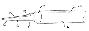
- FIG. 1 is a close-up view of a hollow blow needle according to the present invention
- FIG. 2 is a close-up view of a portion of the hollow blow needle of FIG. 1 ;
- FIG. 3 is a sectional view of a portion of the hollow blow needle of FIG. 1 and FIG. 2 taken along the line A-A of FIG. 2 ;
- FIG. 4 is a view along the longitudinal axis of the blow needle of FIG. 2 ;
- FIG. 5 is an illustration of a mold half in accordance with the present invention.
- FIG. 6 is an illustration of a vertical rotary blow molding machine
- FIG. 7 is an illustration of a feature of the present invention.
- the present invention is directed to an article and method for extrusion blow molding PET and, preferably extrusion grade PET (EPET), at high output rates that are characteristic of vertical wheel-type continuous extrusion blow molding machines such as, for example a Graham Wheel Standard, Super, or Mega (commercially available from Graham Engineering, York, Pa.).
- Suitable EPET for use in accordance with the present invention is, for example, POLYCLEAR® EBM PET 5505 available from Invista (Spartanburg, S.C.) and Eastman Copolymer PM32177 available from Eastman Chemical Company (Kingsport, Tenn.).
- the present invention is directed to a hollow blow needle for introducing pressurized fluid (e.g., air) into an extruded EPET parison enclosed by a two mold halves defining a container such as, for example, an EPET container having a threaded finish and a handle portion.
- pressurized fluid refers to a pressurized gas or mixtures of gases including, without limitation, air.
- the hollow blow needle of the present invention can be used to introduce a pressurized fluid into a parison made from any material, is particularly suited for use in connection with the manufacturing of EPET containers because, as explained in more detail below, the blow needle of the present invention is able to successfully blow an EPET container despite the poor flow properties of the EPET material at the higher mold temperatures required to process such material.
- the hollow blow needle 10 of the present invention comprises body portion 12 having a first outer diameter (O.D.) of from about 0.426 inches to about 0.446 inches, preferably from about 0.431 inches to about 0.441 inches, and most preferably about 0.436 inches.
- Body portion 12 has a first inner diameter which differs from the first O.D. by the thickness of the wall.
- the first inner diameter preferably ranges from about 0.201 inches to about 0.376 inches, and preferably from about 0.201 inches to about 0.211 inches.
- Hollow blow needle 10 further comprises a neck portion 14 having a second outer diameter, wherein the second outer diameter is less than the first outer diameter of the body portion 12 preferably by from about 44% to about 50% of the first O.D. of body portion 12 , more preferably by from about 46% to about 50% of the first O.D. of body portion 12 , and most preferably about 48% of the first O.D. of body portion 12 .
- the second diameter corresponds to a second inner diameter based upon the thickness of the neck portion 14 between the second diameter and the second inner diameter.
- the second inner diameter preferably ranges from about 0.132 inches to about 0.158 inches, more preferably from about 0.141 inches to about 0.158 inches, and most preferably about 0.141 inches.
- the thickness of neck portion 14 is preferably from about 0.030 inches to about 0.040 inches, and more preferably about 0.035 inches.
- tapered neck portion 15 In between body portion 12 and tip portion 16 is tapered neck portion 15 , which tapers the diameter of the hollow blow needle from the first diameter to the second diameter.
- the tapered neck portion 15 functions to stretch the parison wall rather than just pushing and deflecting it inward when contacting the parison wall. Stretching the parison wall allows for it to be thinned out enough to break open upon introduction of blow air.
- the narrower neck portion 14 allows for an increase in pressure due to reducing contact surface area.
- the tapered neck portion 15 also directs blow air (i.e., pressurized fluid) away from the opposite side of the blow dome and the neck area of the finished bottle. Air directed against the dome can penetrate the other parison wall and leak air that would otherwise be needed for blowing the bottle. Air directed towards the neck would result in distortion of this area and possible bottle quality issues with closure application and sealing.
- blow air i.e., pressurized fluid
- hollow blow needle 10 further comprises a double-angled (or double-tapered) tip portion 16 comprising a first angled portion 18 , a second angled portion 20 , wherein the second angled portion is a different angle relative to the first angled portion.
- the angle of first angled portion 18 is from about 75.7° to about 91.7°, more preferably from about 78.7° to about 88.7°, and most preferably about 83.7°.
- the angle of second angled portion 18 is from about 2° to about 18°, more preferably from about 5° to about 15°, and most preferably 10°.
- the double angled tip portion as defined herein functions to direct pressurized fluid downward into the parison to radially expand the parison against the cavity walls of the mold. Because of the rheological characteristics of the semi-molten EPET, in use, the hollow blow needle of the present invention first stretches the semi-molten EPET parison wall into the mold cavity without piercing the wall followed by delivery of a pressurized fluid to penetrate the parison wall to inflate the parison as will be described in more detail below.
- the temperature of the semi-molten EPET parison during this operation is typically from about 550° F. to about 600° F.
- Hollow blow needle 10 still further comprises an orifice 22 located on tip portion 16 through which pressurized fluid flows.
- the dimensions of orifice 22 are ultimately defined by tip portion 16 , including first angled portion 18 and second angled portion 20 as can be seen in FIG. 2 .
- orifice 22 has an elongated shape.
- the diameter of orifice 22 is typically, the same as the inner diameter of the tip portion 16 (i.e., the second inner diameter).
- the ordinarily skilled artisan will appreciate that the diameter of the orifice is chosen to ensure proper blow air delivery with respect to the operating pressure and volume required to blow the container.
- FIG. 3 and FIG. 4 show additional views of tip portion 16 and its orifice 22 .
- the function of orifice 22 so defined is to direct the flow of pressurized fluid downward as will be explained in more detail below.
- Hollow blow needle 10 may be made from any durable material that renders the needle suitable for its intended use. Such materials include metals or metal alloys such as, for example, stainless steel. The preferred material is stainless steel. Moreover, the length of hollow blow needle 10 may be any suitable length to be determined by one of ordinary skill in the art to ensure proper location of a needle hole in a parison at the time of blowing a container.
- Hollow blow needle 10 is typically delivered to a mold as a component of a blow assembly well known to the skilled artisan (not shown) which may be operated by, for example, a piston rod inserted through the mold at a blow needle insertion orifice.
- a blow needle assembly is typically provided for each mold station and includes a cylinder means (not shown), and a piston means (not shown) that is slidably reciprocal within the cylinder means and carrying the hollow blow needle on its forward end whereby the needle is moved into and out of a portion of the molding cavity.
- the present invention provides a method of blow molding an article from a parison comprising EPET.
- the method comprises the step of positioning an extruded parison comprising EPET in a cavity defined by two mold halves, wherein the parison is defined by at least one wall comprising EPET, and wherein the cavity comprises walls that define the shape of a container comprising a handle portion and a blow dome portion.
- FIG. 5 illustrates an exemplary mold half that can, with its corresponding second half, be mounted upon conventional supporting and operating mechanisms for lateral movement between the separated mold half position (not shown) and the closed mold half position shown in the drawings.
- FIG. 5 illustrates an exemplary mold half that can, with its corresponding second half, be mounted upon conventional supporting and operating mechanisms for lateral movement between the separated mold half position (not shown) and the closed mold half position shown in the drawings.
- cavity 34 may include a generally semi-cylindrical neck defining portion 36 , laterally offset from the axial center line, which is formed by cooperating semi-cylindrical portions of the mold halves. Situated above and laterally offset from the neck defining portions of the mold walls, mold half 32 may include a recess 38 that forms a semi-cylindrical passage that will ultimately define a blow dome on the article defined by the mold. Blow needle channel 44 is located on recess 38 .
- Hollow depression 40 of mold half 32 Communicating with and located laterally beside recess 38 and axially above the body defining portions of the mold walls is hollow depression 40 of mold half 32 in the excess material portion 54 of mold half 32 that will become the shoulder flash on the article being molded. Hollow depression 40 and recess 38 are in communication with each other through passage 50 .
- FIG. 6 depicts a vertical rotary blow molding machine 100 .
- a typical blow molding machine represented by FIG. 6 is, for example, a Graham WheelTM continuous vertical rotary blow molding machine (Graham Engineering, York, Pa.).
- the blow molding machine 100 rests on a base 112 and includes a rotatable wheel 114 and an extruder 115 .
- the wheel 114 comprises a plurality of identical in-line molds 116 , each mold 116 having an identical inner cavity 117 defining a container comprising a handle portion.
- Rotary blow molding machines typically have anywhere from 6 to 30 molds.
- the identical in-line molds 116 are mounted on wheel 114 preferably about the perimeter thereof, for rotation therewith about a rotational axis 113 .
- the identical in-line molds 116 each preferably have a pair of mold halves (not shown) that split the respective inner cavities 117 , and which open and close at various stations (described below) during rotation about the rotational axis 113 consistent with operation of a conventional wheel type extrusion blow molding apparatus.
- the extruder 115 includes a die 130 located adjacent to the wheel 114 and defining a filling station 182 at which a series of hot plastic parisons are extruded from the die 130 .
- the die 130 is positioned such that when the identical in-line molds 116 are continuously rotated to the filling station 182 by the wheel 114 , the hot plastic parisons extruded from the die 130 may be accepted into the respective inner cavities 117 according to conventional wheel type blow moldings techniques.
- a parison supplied by the die 130 will typically have a varying thickness profile along a length thereof to assure that upon the stretching experienced during blowing, the bottle will have the desired wall thickness at the various portions thereof.
- the thickness of the parison for such a bottle may be, for example, relatively thicker at a top and bottom thereof corresponding to a neck and bottom portion of a bottle blown therefrom.
- a pin 128 of the die 130 controls the thickness of a wall of each parison extruded.
- the pin 128 is coupled to a hydraulic cylinder 131 by a drawbar (not shown) such that the hydraulic cylinder 131 may vary the position of the pin 128 during extrusion of a parison.
- the hydraulic cylinder 131 thus raises and lowers the pin 128 to vary the thickness of the parison as it is extruded.
- the controller 120 controls the hydraulic cylinder 131 and thus the positioning of the pin 128 .
- the controller 120 has programmed therein, in a manner well-known to those skilled in the art, a preset pin control program or routine to control the vertical movement of the pin 128 during extrusion of each parison and manifests control of the pin 128 via the hydraulic cylinder 131 as is also known in the art. In this manner, the pin control program determines the thickness profile of the parison. The controller 120 also induces extrusion of the parison from the die 130 upon indication from the trigger mechanism 188 that a mold is in place and/or that a parison is required.
- the method of the present invention also comprises the step of introducing the hollow blow needle as detailed above into the mold to contact a portion of the wall of the parison in the blow dome portion of the cavity to stretch the portion of the wall into the cavity.
- a parison is extruded from the die 130 and the mold halves of one of the identical in-line molds 116 close around the parison such that the parison is received by the inner cavity 117 .
- the double-tapered tip portion 16 (not shown in FIG. 6 ) stretches the EPET parison wall into the mold cavity without piercing the parison wall under conventional operating conditions as detailed above. This is, in part, due to the rheological properties of the extrusion grade PET at operating temperatures of from about 550° F. to about 600° F. and, in part, due to the hollow blow needle of the present invention.
- the method of the present invention also includes the step of introducing a pressurized fluid through the hollow blow needle to puncture the wall and inflate the parison against the walls of the cavity thus forming the container defined by the cavity, wherein the hollow blow needle directs the pressurized fluid away from the blow dome portion.
- Hollow blow needle 10 is attached to a source of pressurized fluid and is operable to be moved within a passage in a mold half. Hollow blow needle 10 may be reciprocally driven by a variety of mechanisms including hydraulic and pneumatic cylinders, motors and solenoids as are well-known in the art.
- Article 200 comprises a threaded portion 205 and a blow dome 210 (prior to removal of the dome).
- hollow blow needle 10 according to the present invention is shown.
- Stretched wall portion 225 is shown which is caused by the double-tapered tip portion 16 of hollow blow needle 10 .
- the flow of pressurized fluid punctures the wall of the EPET parison.
- a portion of the pressurized fluid may be directed at a point opposite the tip portion 16 , the directional arrows in FIG.
- FIG. 7 illustrate that the majority of the volume of pressurized fluid introduced into the EPET parison is directed downward and away from the blow dome 210 .
- the pressurized fluid from hollow blow needle 10 radially expands the parison to conform to the shape and size of the inner cavity of the mold thereby forming a container.
- the EPET parison is “pre-blown” in that it is partially inflated by means of a gas introduced therein from the extruder from which the parison is extruded. Typically, this pre-blown condition is obtained immediately prior to closure of the mold halves.
- wheel 114 continues its rotation in a conventional manner. Once blown and at least partially cooled, the container is thereafter released by opening the mold halves at a release station 186 .
- the wheel 114 can produce at least 75 bottles per minute.
- a Mega 20 Graham Wheel producing 59 oz. bottles operates at 5 revolutions per minute to produce about 100 bottles per minute.
- the hollow blow needle of the present invention is suitable for use in an EBM process wherein the output rate is at least 75-100 BPM.
Abstract
Description
Claims (19)
Priority Applications (2)
| Application Number | Priority Date | Filing Date | Title |
|---|---|---|---|
| US12/893,665 US8523557B2 (en) | 2010-09-29 | 2010-09-29 | Blow needle for extrusion blow molding PET |
| PCT/US2011/049901 WO2012044431A1 (en) | 2010-09-29 | 2011-08-31 | Blow needle for extrusion blow molding pet and method of blow molding an article from a parison comprising epet |
Applications Claiming Priority (1)
| Application Number | Priority Date | Filing Date | Title |
|---|---|---|---|
| US12/893,665 US8523557B2 (en) | 2010-09-29 | 2010-09-29 | Blow needle for extrusion blow molding PET |
Publications (2)
| Publication Number | Publication Date |
|---|---|
| US20120074619A1 US20120074619A1 (en) | 2012-03-29 |
| US8523557B2 true US8523557B2 (en) | 2013-09-03 |
Family
ID=44584684
Family Applications (1)
| Application Number | Title | Priority Date | Filing Date |
|---|---|---|---|
| US12/893,665 Expired - Fee Related US8523557B2 (en) | 2010-09-29 | 2010-09-29 | Blow needle for extrusion blow molding PET |
Country Status (2)
| Country | Link |
|---|---|
| US (1) | US8523557B2 (en) |
| WO (1) | WO2012044431A1 (en) |
Citations (22)
| Publication number | Priority date | Publication date | Assignee | Title |
|---|---|---|---|---|
| US3571848A (en) * | 1969-01-14 | 1971-03-23 | Continental Can Co | High exhaust needle |
| US3869237A (en) * | 1972-12-20 | 1975-03-04 | Continental Can Co | Mold assembly |
| US3932084A (en) | 1974-12-16 | 1976-01-13 | Monsanto Company | Blow needle assembly |
| US4046498A (en) | 1975-10-08 | 1977-09-06 | Gildemeister Corpoplast Gmbh | Apparatus for blow-molding hollow articles, in particular bottles |
| US4080146A (en) * | 1974-11-22 | 1978-03-21 | The Continental Group, Inc. | Segmented blow molds |
| US4161579A (en) | 1978-04-10 | 1979-07-17 | Celanese Corporation | Extrusion grade polyethylene terephthalate |
| US4859397A (en) | 1988-02-22 | 1989-08-22 | Phillips Petroleum Company | Preventing gas leakage around blow needle in blow molding method |
| US4867197A (en) | 1989-02-15 | 1989-09-19 | Fetterolf Corporation | High pressure valve |
| US4943228A (en) | 1988-05-04 | 1990-07-24 | Krupp Corpoplast Maschinenbau Gmbh | Blow molding machine |
| US4946366A (en) | 1989-06-22 | 1990-08-07 | Graham Engineering Corporation | Needle assembly for blow molding aseptic bottles |
| US5078948A (en) | 1991-04-30 | 1992-01-07 | Ford Motor Company | Arrowhead tip blow needle and method of using the needle to blow mold an article |
| WO1992003276A1 (en) | 1990-08-13 | 1992-03-05 | Plastipak Packaging, Inc. | Blow molding of polyethylene terephthalate |
| US5565165A (en) * | 1994-08-22 | 1996-10-15 | Toyo Seikan Kaisha, Ltd. | Method for blow molding hollow articles |
| US5939108A (en) | 1996-07-08 | 1999-08-17 | Toyo Seikan Kaisya, Ltd. | Blow air cylinder for blow-molding hollow container |
| WO2002072334A2 (en) | 2001-03-13 | 2002-09-19 | 'fasti' Farrag & Stipsits Gmbh | Method for producing plastic molded parts using a blowing mold and an injection lance |
| JP2004223816A (en) | 2003-01-21 | 2004-08-12 | Honda Motor Co Ltd | Blow molding method and apparatus therefor |
| US20060290033A1 (en) | 2005-06-22 | 2006-12-28 | Ovidiu Purdel | Blow molding needle |
| DE102005029916A1 (en) | 2005-06-28 | 2007-03-08 | Sig Technology Ltd. | Food stuff e.g. beverage, filling containers blow molding method, involves operating rotary transfer wheel for transferring of pre-forms to blow wheel and removing of blown container from blow wheel by support arms with two retaining units |
| CN200977723Y (en) | 2006-11-30 | 2007-11-21 | 蔡佳祎 | Slipway type automatic blank feeding mechanism for plastic pulling and blowing machine |
| US20090085243A1 (en) | 2007-09-27 | 2009-04-02 | Graham Packaging Company, L.P. | Apparatus and method for producing a multi-layer parison having a layer of varying thickness |
| WO2009059091A1 (en) | 2007-10-31 | 2009-05-07 | Graham Packaging Company, L.P. | Blow molding machine and associated mechanisms |
| US7766645B2 (en) | 2005-02-08 | 2010-08-03 | Sidel Participations | Method of controlling the opening and closing of a blow mold and blowing device for implementing same |
-
2010
- 2010-09-29 US US12/893,665 patent/US8523557B2/en not_active Expired - Fee Related
-
2011
- 2011-08-31 WO PCT/US2011/049901 patent/WO2012044431A1/en active Application Filing
Patent Citations (22)
| Publication number | Priority date | Publication date | Assignee | Title |
|---|---|---|---|---|
| US3571848A (en) * | 1969-01-14 | 1971-03-23 | Continental Can Co | High exhaust needle |
| US3869237A (en) * | 1972-12-20 | 1975-03-04 | Continental Can Co | Mold assembly |
| US4080146A (en) * | 1974-11-22 | 1978-03-21 | The Continental Group, Inc. | Segmented blow molds |
| US3932084A (en) | 1974-12-16 | 1976-01-13 | Monsanto Company | Blow needle assembly |
| US4046498A (en) | 1975-10-08 | 1977-09-06 | Gildemeister Corpoplast Gmbh | Apparatus for blow-molding hollow articles, in particular bottles |
| US4161579A (en) | 1978-04-10 | 1979-07-17 | Celanese Corporation | Extrusion grade polyethylene terephthalate |
| US4859397A (en) | 1988-02-22 | 1989-08-22 | Phillips Petroleum Company | Preventing gas leakage around blow needle in blow molding method |
| US4943228A (en) | 1988-05-04 | 1990-07-24 | Krupp Corpoplast Maschinenbau Gmbh | Blow molding machine |
| US4867197A (en) | 1989-02-15 | 1989-09-19 | Fetterolf Corporation | High pressure valve |
| US4946366A (en) | 1989-06-22 | 1990-08-07 | Graham Engineering Corporation | Needle assembly for blow molding aseptic bottles |
| WO1992003276A1 (en) | 1990-08-13 | 1992-03-05 | Plastipak Packaging, Inc. | Blow molding of polyethylene terephthalate |
| US5078948A (en) | 1991-04-30 | 1992-01-07 | Ford Motor Company | Arrowhead tip blow needle and method of using the needle to blow mold an article |
| US5565165A (en) * | 1994-08-22 | 1996-10-15 | Toyo Seikan Kaisha, Ltd. | Method for blow molding hollow articles |
| US5939108A (en) | 1996-07-08 | 1999-08-17 | Toyo Seikan Kaisya, Ltd. | Blow air cylinder for blow-molding hollow container |
| WO2002072334A2 (en) | 2001-03-13 | 2002-09-19 | 'fasti' Farrag & Stipsits Gmbh | Method for producing plastic molded parts using a blowing mold and an injection lance |
| JP2004223816A (en) | 2003-01-21 | 2004-08-12 | Honda Motor Co Ltd | Blow molding method and apparatus therefor |
| US7766645B2 (en) | 2005-02-08 | 2010-08-03 | Sidel Participations | Method of controlling the opening and closing of a blow mold and blowing device for implementing same |
| US20060290033A1 (en) | 2005-06-22 | 2006-12-28 | Ovidiu Purdel | Blow molding needle |
| DE102005029916A1 (en) | 2005-06-28 | 2007-03-08 | Sig Technology Ltd. | Food stuff e.g. beverage, filling containers blow molding method, involves operating rotary transfer wheel for transferring of pre-forms to blow wheel and removing of blown container from blow wheel by support arms with two retaining units |
| CN200977723Y (en) | 2006-11-30 | 2007-11-21 | 蔡佳祎 | Slipway type automatic blank feeding mechanism for plastic pulling and blowing machine |
| US20090085243A1 (en) | 2007-09-27 | 2009-04-02 | Graham Packaging Company, L.P. | Apparatus and method for producing a multi-layer parison having a layer of varying thickness |
| WO2009059091A1 (en) | 2007-10-31 | 2009-05-07 | Graham Packaging Company, L.P. | Blow molding machine and associated mechanisms |
Non-Patent Citations (1)
| Title |
|---|
| International Search Report and Written Opinion mailed Nov. 28, 2011 for corresponding international patent application No. PCT/US2011/049901. |
Also Published As
| Publication number | Publication date |
|---|---|
| US20120074619A1 (en) | 2012-03-29 |
| WO2012044431A1 (en) | 2012-04-05 |
Similar Documents
| Publication | Publication Date | Title |
|---|---|---|
| US7153127B2 (en) | Method and apparatus for blow molding hollow plastic containers | |
| US5795533A (en) | Method and device for the manufacturing of hollow articles made from thermoplastic material by blow moulding | |
| US8523557B2 (en) | Blow needle for extrusion blow molding PET | |
| US7153466B2 (en) | Method and apparatus for blow-molding an article having a solid radially outwardly projecting flange | |
| EP0241040A1 (en) | Manufacture of plastic bottles | |
| US7037101B2 (en) | Center cylinder ejection assist | |
| US20060255513A1 (en) | Mold gap seal | |
| JP3578157B2 (en) | Compression molding equipment for compression molding of preforms for blow molding | |
| US8366437B2 (en) | Angle link pivot bracket for wheel | |
| CN205033559U (en) | Foldable pail pack blowing mould | |
| US20230226740A1 (en) | Method of forming a container having a hanging implement | |
| CN216832152U (en) | Stretching rod and device for inflating preforms | |
| WO2021221024A1 (en) | Method for manufacturing resin wide-mouthed container, manufacturing device, and resin wide-mouthed container | |
| US8388333B2 (en) | Systems for purging polyethylene terephthalate from an extrusion blow molding apparatus | |
| CN106273366A (en) | A kind of bottle blowing machine bottleneck formation system smoke treating device | |
| CN105172108A (en) | Foldable packaging barrel blow mold | |
| KR102006384B1 (en) | method of manufacturing hollow article having constant thickness by blow molding, manufacturing apparatus, and hollow article | |
| Raber | Blowmolding | |
| GB2053775A (en) | Extrusion/blow moulding of plastics articles | |
| AU2004202706A1 (en) | Accumulating extrusion blow moulding process | |
| CA2684355A1 (en) | Extrusion molding technique and synthetic stopper produced therefrom | |
| WO2004065103A1 (en) | Apparatus and method of manufacturing hollow articles | |
| CN104943135A (en) | Round package bucket blowing mould | |
| EP2019746A2 (en) | In-mold finished neck on a continuous extrusion blow molder | |
| IE85629B1 (en) | A plastic blow-moulding process |
Legal Events
| Date | Code | Title | Description |
|---|---|---|---|
| AS | Assignment |
Owner name: GRAHAM PACKAGING COMPANY, L.P., PENNSYLVANIA Free format text: ASSIGNMENT OF ASSIGNORS INTEREST;ASSIGNORS:BURNS, JASON E.;TAYLOR, LARRY M.;PERRING, WAYNE;REEL/FRAME:025073/0552 Effective date: 20100929 |
|
| AS | Assignment |
Owner name: REYNOLDS GROUP HOLDINGS INC., NEW ZEALAND Free format text: SECURITY AGREEMENT;ASSIGNOR:GRAHAM PACKAGING COMPANY, L.P.;REEL/FRAME:026970/0699 Effective date: 20110908 |
|
| AS | Assignment |
Owner name: GRAHAM PACKAGING COMPANY, L.P., PENNSYLVANIA Free format text: TERMINATION AND RELEASE OF SECURITY INTEREST IN PATENTS;ASSIGNOR:REYNOLDS GROUP HOLDINGS INC.;REEL/FRAME:027895/0738 Effective date: 20120320 |
|
| AS | Assignment |
Owner name: THE BANK OF NEW YORK MELLON, NEW YORK Free format text: PATENT SECURITY AGREEMENT;ASSIGNOR:GRAHAM PACKAGING COMPANY, L.P.;REEL/FRAME:027910/0609 Effective date: 20120320 |
|
| STCF | Information on status: patent grant |
Free format text: PATENTED CASE |
|
| FPAY | Fee payment |
Year of fee payment: 4 |
|
| AS | Assignment |
Owner name: GRAHAM PACKAGING COMPANY, L.P., PENNSYLVANIA Free format text: RELEASE OF SECURITY INTEREST IN CERTAIN PATENT COLLATERAL;ASSIGNOR:THE BANK OF NEW YORK MELLON, AS THE COLLATERAL AGENT AND TRUSTEE;REEL/FRAME:053396/0531 Effective date: 20200804 Owner name: CREDIT SUISSE AG, CAYMAN ISLANDS BRANCH, AS ADMINISTRATIVE AGENT, NEW YORK Free format text: SECURITY INTEREST;ASSIGNORS:GRAHAM PACKAGING COMPANY, L.P.;GRAHAM PACKAGING PET TECHNOLOGIES INC.;GRAHAM PACKAGING PLASTIC PRODUCTS LLC;REEL/FRAME:053398/0381 Effective date: 20200804 |
|
| FEPP | Fee payment procedure |
Free format text: MAINTENANCE FEE REMINDER MAILED (ORIGINAL EVENT CODE: REM.); ENTITY STATUS OF PATENT OWNER: LARGE ENTITY |
|
| LAPS | Lapse for failure to pay maintenance fees |
Free format text: PATENT EXPIRED FOR FAILURE TO PAY MAINTENANCE FEES (ORIGINAL EVENT CODE: EXP.); ENTITY STATUS OF PATENT OWNER: LARGE ENTITY |
|
| STCH | Information on status: patent discontinuation |
Free format text: PATENT EXPIRED DUE TO NONPAYMENT OF MAINTENANCE FEES UNDER 37 CFR 1.362 |
|
| FP | Lapsed due to failure to pay maintenance fee |
Effective date: 20210903 |